Pepperl+Fuchs LAL-SRW series Benutzerhandbuch
- Typ
- Benutzerhandbuch

LAL-SRW
WARNING DEVICE
WARNANLAGE
SYSTÈME D’ALARME
ALARMRELÆ
EN
DE
FR
DA
PROCESS AUTOMATION
MANUAL
По вопросам продаж и поддержки обращайтесь:
Архангельск (8182)63-90-72
Астана +7(7172)727-132
Белгород (4722)40-23-64
Брянск (4832)59-03-52
Владивосток (423)249-28-31
Волгоград (844)278-03-48
Вологда (8172)26-41-59
Воронеж (473)204-51-73
Екатеринбург (343)384-55-89
Иваново (4932)77-34-06
Ижевск (3412)26-03-58
Казань (843)206-01-48
Калининград (4012)72-03-81
Калуга (4842)92-23-67
Кемерово (3842)65-04-62
Киров (8332)68-02-04
Краснодар (861)203-40-90
Красноярск (391)204-63-61
Курск (4712)77-13-04
Липецк (4742)52
-20-81
Магнитогорск (3519)55-03-13
Москва (495)268-04-70
Мурманск (8152)59-64-93
Набережные Челны (8552)20-53-41
Нижний Новгород (831)429-08-12
Новокузнецк (3843)20-46-81
Новосибирск (383)227-86-73
Орел (4862)44
-53-42
Оренбург (3532)37-68-04
Пенза (8412)22-31-16
Пермь (342)205-81-47
Ростов-на-Дону (863)308-18-15
Рязань (4912)46-61-64
Самара (846)206-03-16
Санкт-Петербург (812)309-46-40
Саратов (845)249-38-78
Смоленск (4812)29-41-54
Сочи (862)225-72-31
Ставрополь (8652)20-65-13
Тверь (4822)63-31-35
Томск (3822)98-41-53
Тула (4872)74-02-29
Тюмень (3452)66-21-18
Ульяновск (8422)24-23-59
Уфа (347)229-48-12
Челябинск (351)202-03-61
Череповец (8202)49-02-64
Ярославль (4852)69-52-93
Единый адрес: [email protected] | http://pepperl.nt-rt.ru

With regard to the supply of products, the current issue of the following docu-
ment is applicable: The General Terms of Delivery for Products and Services of
the Electrical Industry, published by the Central Association of the Electrical In-
dustry (Zentralverband Elektrotechnik und Elektroindustrie (ZVEI) e.V.) in its
most recent version as well as the supplementary clause: "Expanded reservation
of proprietorship"
Es gelten die Allgemeinen Lieferbedingungen für Erzeugnisse und Leistungen
der Elektroindustrie, herausgegeben vom Zentralverband Elektroindustrie
(ZVEI) e.V. in ihrer neusten Fassung sowie die Ergänzungsklausel: "Erweiterter
Eigentumsvorbehalt".
Les conditions de vente générales pour les produits et les services de l'industrie
des équipements électriques publiées par la Fédération de l'industrie électron-
ique (ZVEI) s'appliquent dans leur toute dernière version, tout comme la clause
complémentaire "Réserve de propriété élargie".
De almene leveringsbetingelser for produkter og ydelser fra elektronikindustrien,
der er udgivet af Zentralverband Elektroindustrie (ZVEI) e.V. i den seneste ud-
gave samt tillægsklasulen: "Udvidet ejendomforbehold" er gældende".
EN
DE
FR
DA
WARNING DEVICE LAL-SRW

WARNING DEVICE LAL-SRW
Contents
233717 2011-05
EN - 1
EN
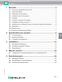
1 Safety................................................................................... 3
1.1 General Safety Instructions ...........................................................................3
1.2 Used Symbols...............................................................................................3
1.3 Declaration of Conformity..............................................................................4
1.4 Intended Use ................................................................................................4
1.5 Maintenance .................................................................................................5
1.6 Delivery, Transport and Storage ....................................................................5
1.7 Installation and Commissioning ....................................................................6
1.8 Installation in Connection with Intrinsically Safe Circuits ...............................6
1.9 Repair ...........................................................................................................7
1.10 Disposal........................................................................................................7
1.11 Applied Standards and Directives .................................................................7
2 Product Specifications....................................................... 8
2.1 Function........................................................................................................8
2.2 Product Program...........................................................................................8
2.3 Design and Dimensions................................................................................9
3 Installation......................................................................... 10
3.1 Mounting of the Sensors.............................................................................10
3.2 Mounting of the Warning Device .................................................................15
3.3 Connection .................................................................................................16
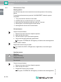
4 Commissioning................................................................. 23
4.1 Configuring the Warning Device using DIP Switches ..................................23
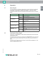
5 Operation........................................................................... 25
5.1 Alarm Signals..............................................................................................25
5.2 Resetting the Alarm Signal..........................................................................25
5.3 Performance Test........................................................................................26

233717 2011-05
2 - EN
WARNING DEVICE LAL-SRW
Contents
EN
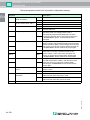
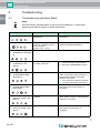
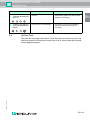
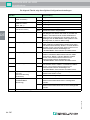
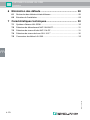
6 Troubleshooting ............................................................... 28
6.1 Troubleshooting and Alarm States.............................................................. 28
6.2 System Care............................................................................................... 29
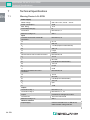
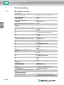
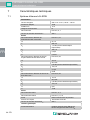
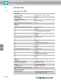
7 Technical Specifications.................................................. 30
7.1 Warning Device LAL-SRW ......................................................................... 30
7.2 Overflow Sensor NVF-104/34-PF............................................................... 31
7.3 Oil Level Sensor KVF-104-PF .................................................................... 31
7.4 Sludge Level Sensor SLU-103-** ............................................................... 32
7.5 Cable Connector LAL-SK2......................................................................... 32

WARNING DEVICE LAL-SRW
Safety
233717 2011-05
EN - 3
EN
1Safety
1.1 General Safety Instructions
The plant owner is responsible for its planning, installation, commissioning,
operation, maintenance and disassembly.
Installation and commissioning of all devices must be performed by a trained
professional only.
Protection of operating personnel and the system is not ensured if the product is
not used in accordance with its intended purpose.
Laws and regulations applicable to the usage or the intended purpose must be
observed. The devices are only approved for appropriate and intended use.
Ignoring these instructions will void any warranty and absolve the manufacturer
from any liability.
The Declaration of Conformity, Certificate of Compliance, Statement of
Conformity, EC-type-examination certificate and data sheets are an integral part of
this document.
The data sheet contains the electrical data of the Declaration of Conformity, the
Certificate of Compliance and the EC-type-examination certificate.
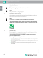
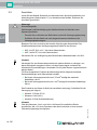
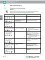
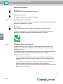
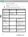
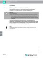
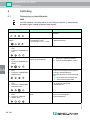
1.2 Used Symbols
Safety-relevant Symbols
Danger!
This symbol indicates a warning about a possible danger.
In case of ignoring the consequences may range from personal injury to death.
Warning!
This symbol indicates a warning about a possible fault or danger.
In case of ignoring the consequences may cause personal injury or heaviest
property damage.
Caution!
This symbol warns of a possible fault.
In case of ignoring the devices and any connected facilities or systems may be
interrupted or fail completely.

233717 2011-05
4 - EN
WARNING DEVICE LAL-SRW
Safety
EN
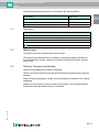
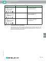
Informative Symbols
Action
This symbol marks an acting paragraph.
1.3 Declaration of Conformity
All products have been developed and manufactured taking into consideration
applicable European standards and regulations.
The manufacturer of this product, Pepperl+Fuchs GmbH in 68307 Mannheim,
Germany, has a certified quality assurance system in conformity with ISO 9001.
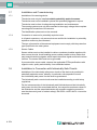
1.4 Intended Use
The warning device is a compact alarm system for monitoring sensors in the
Zone 0 hazardous area of oil/petrol separators.
The warning devices must only be installed in a suitable control cabinet or
NVO5-KV installation housing.
The warning device was designed to detect:
■ the oil layer thickness, the maximum level of the liquid or the sludge level if
one sensor is connected,
■ the oil layer thickness and the maximum level of the liquid if two sensors are
connected or
■ the sludge level and the maximum level of the liquid if two sensors are
connected.
Note!
This symbol brings important information to your attention.
Note!
A Declaration of Conformity can be requested from the manufacturer.
ISO9001

WARNING DEVICE LAL-SRW
Safety
233717 2011-05
EN - 5
EN
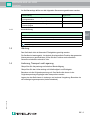
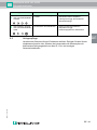
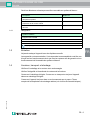
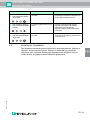
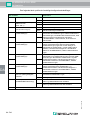
Only the following sensors must be connected to the warning device:
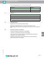
1.4.1 Designation
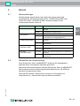
1.5 Maintenance
The device must not be cleaned with caustic fluids.
The devices are maintenance-free. However, to guarantee perfect operation of
the complete alarm system, check the operation, including all sensors, at least
once a year.
1.6 Delivery, Transport and Storage
Check the packaging and contents for damage.
Check if you have received every item and if the items received are the ones you
ordered.
Keep the original packaging. Always store and transport the device in the original
packaging.
Always store the device in a clean and dry environment. The permitted storage
temperature (see data sheet) must be considered.
Description Typ e co de
Overflow sensor, for detecting excessively high liquid level NVF-104/34-PF
Oil level sensor, for detecting of oil layer thickness KVF-104-PF
Sludge level sensor, for detecting sludge levels SLU-103-**
Warning device
Pepperl+Fuchs GmbH
Lilienthalstrasse 200, 68307 Mannheim, Germany
LAL-SRW
BVS 09 ATEX E 137
II (1)G [Ex ia] IIB

233717 2011-05
6 - EN
WARNING DEVICE LAL-SRW
Safety
EN
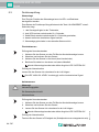
1.7 Installation and Commissioning
1.7.1 Installation of the warning device
The device must only be installed outside potentially explosive zones.
The device must not be installed in places with potentially aggressive vapors.
The device must be free of voltage during installation and maintenance.
The warning system must only be connected to the supply voltage after complete
mounting and connection of the sensors.
The identification plate must not be removed.
1.7.2 Connection to sensors for potentially explosive zone
In oil/petrol separators, only sensors that are certified for installation in potentially
explosive zones may be connected.
The type of protection of the external equipment must comply with the protection
type specified for the total system.
1.7.3 Sensor Cables
Sensor cables must not be installed in cable or conductor bundles together with
other current circuits. Avoid installing sensor cables parallel to other cables that
may transmit interfering signals, which impair the sensor signal and thus the alarm
function. The sensor itself must not be grounded.
If you extend the sensor cable, observe the applicable ATEX specifications with
regard to color, quality and durability. Use unshielded cables.
1.8 Installation in Connection with Intrinsically Safe Circuits
Installation of the intrinsically safe power circuits of the devices is permitted in
potentially explosive zones, whereby, in particular, safe separation from all
non-intrinsically safe power circuits must be guaranteed.
The intrinsically safe current circuits must be installed according to valid setup
regulations.
For the interconnection of the intrinsically safe field devices and the intrinsically
safe power circuits of the associated devices, the respective maximum values of
the field device and the associated device with regard to explosion protection
must be observed (proof of intrinsic safety). EN 60079-14/IEC 60079-14 must be
observed.

WARNING DEVICE LAL-SRW
Safety
233717 2011-05
EN - 7
EN
1.9 Repair
The devices must not be repaired, changed or manipulated. If there is a defect,
the product must always be replaced with an original device.
1.10 Disposal
Disposal of devices and their packaging material must be performed in
compliance with the applicable laws and guidelines of the corresponding country.
The devices do not contain batteries which need to be disposed of separately
from the products.
1.11 Applied Standards and Directives
EN 60079-0:2009
EN 60079-11:2007
EN 60079-26:2007
EN 50178
EN 61326-1:2006
NAMUR NE21:2007
EN 61000-6-4:2007
ATEX Directive 94/9/EC
EMC Directive 2004/108/EC
Low Voltage Directive 2006/95/EC

233717 2011-05
8 - EN
WARNING DEVICE LAL-SRW
Product Specifications
EN
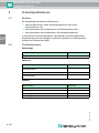
2 Product Specifications
2.1 Function
The warning device monitors the status of
■ an overflow sensor, a sludge level sensor or an oil layer sensor, or
■ a combination of an overflow sensor and an oil level sensor or
■ a combination of an overflow sensor and a sludge level sensor
in an oil/petrol separator. LEDs on the device indicate an alarm, sensor fault and
system and sensor status. In the event of an alarm, an additional acoustic signal
sounds.
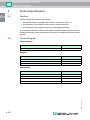
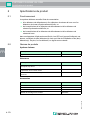
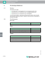
2.2 Product Program
Warning device
Sensors
Accessories
Description Type c ode
Intrinsically safe warning device, 230 V AC LAL-SRW
Description Type c ode
Overflow sensor, for detecting excessively high liquid level NVF-104/34-PF
Oil level sensor, for detecting of oil layer thickness KVF-104-PF
Sludge level sensor, for detecting sludge levels SLU-103-**
Description Type c od e
Connection box IP67 NVO5-VD
Cable connector IP68 for one sensor LAL-SK2
Mounting set for one sensor NVO5-B
Installation housing with DIN mounting rail NVO5-KV

WARNING DEVICE LAL-SRW
Product Specifications
233717 2011-05
EN - 9
EN
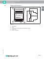
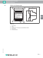
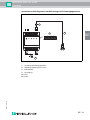
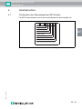
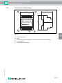
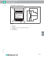
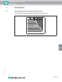
2.3 Design and Dimensions
Figure 2.1
1 DIP switches
2 LEDs
3 Connections for power supply and potential-free contacts
4 Reset button
5 Sensor connections
LAL-SRW
ALARM
RESET
HIGH OIL
LEVEL
SYSTEM
OK
OVERFLOW
ALARM
SUPPLY
Separator Alarm System
70
58
86
54
4
23
5
1

233717 2011-05
10 - EN
WARNING DEVICE LAL-SRW
Installation
EN
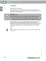
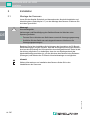
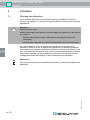
3 Installation
3.1 Mounting of the Sensors
Read the Safety chapter, paying particular attention to the section covering
Installation and Commissioning (see chapter 1.7) before mounting the sensor. Do
not remove the identification plate.
During installation, refer to the instructions provided by the oil/petrol separator
manufacturer. Ensure that the suspension mechanism keeps the sensor
permanently at the correct height. Where possible, secure the device in a position
where it can be reached from the manhole opening so that it can be removed
when emptying (disposal) or carrying out maintenance work on the oil/petrol
separator.
Warning!
Risk of short circuit
Injuries and damage to the device are possible when working with live parts.
■ Before working on the device, always disconnect the supply voltage.
■ Connect the device to the supply voltage only after completion of the work.
Note!
Further information on the installation of the sensor is available in the manuals of
the sensors.

WARNING DEVICE LAL-SRW
Installation
233717 2011-05
EN - 11
EN
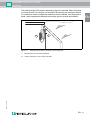
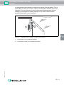
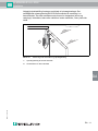
The precise height of the sensor depends on how it is mounted. When mounting
in a concrete tank, for example, use the NVO5-B mounting set (see figure below).
For containers, tanks or separators made from other materials, such as plastic or
metal, use the appropriate alternative mounting options (screws and dowels).
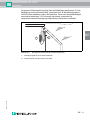
Figure 3.1 Mounting using cable connector and mounting set
1 Mounting set for one sensor NVO5-B
2 Cable connector for one sensor LAL-SK2
2
1

233717 2011-05
12 - EN
WARNING DEVICE LAL-SRW
Installation
EN
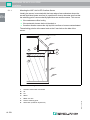
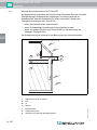
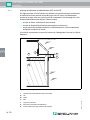
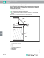
3.1.1 Mounting the NVF-104/34-PF Overflow Sensor
Usually, the sensor is mounted with the lower edge a few centimeters above the
normal liquid level (water zero line) in a position so close to the water zero line that
the switching point is surrounded by liquid when an overflow occurs. This occurs
■ if the coalescence filter is dirty,
■ if the automatic closure device is blocked, or
■ if another situation causes the oily liquid to overflow or become contaminated.
The switching point is at the same level as the 5 mm hole on the side of the
sensor.
Figure 3.2 Mounting the overflow sensor
1 Overflow sensor NVF-104/34-PF
A Air
B Oil
C Water
L Water zero line
S Sensor switching point
X Alarm limit (maximum liquid level)
B
C
A
1
L
S
X

WARNING DEVICE LAL-SRW
Installation
233717 2011-05
EN - 13
EN
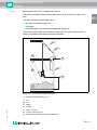
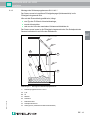
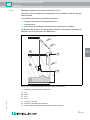
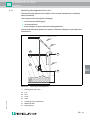
3.1.2 Mounting the SLU-103-** Sludge Level Sensor
The sensor must be immersed when the liquid is at its normal level (water zero
line).
The exact immersion depth depends on
■ the type of oil/petrol separator,
■ its design
■ and the height of the maximum sludge layer thickness.
The sensor must always be immersed in the liquid. The switching point of the
sensor is located at the same level as the reflectors.
Figure 3.3 Mounting the sludge level sensor
1 Sludge level sensor SLU-103-**
A Air
B Oil
C Water
D Sludge
L Water zero line
S Sensor switching point
X Alarm limit (maximum sludge layer thickness)
C
A
D
1
L
S
B
X

233717 2011-05
14 - EN
WARNING DEVICE LAL-SRW
Installation
EN
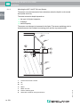
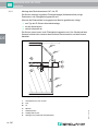
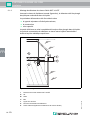
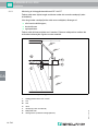
3.1.3 Mounting the KVF-104-PF Oil Level Sensor
The sensor must be immersed a few centimeters when the liquid is at its normal
level (water zero line).
The exact immersion depth depends on
■ the type of oil/petrol separator,
■ its design
■ and its capacity.
The sensor must always be immersed in the liquid. The sensor switching point is
located between the insulated connecting piece and the top metal section.
Figure 3.4 Mounting the oil level sensor
1 Oil level sensor KVF-104-PF
A Air
B Oil
C Water
L Water zero line
S Sensor switching point
X Alarm limit (maximum oil layer thickness)
L
S
B
C
A
1
X

WARNING DEVICE LAL-SRW
Installation
233717 2011-05
EN - 15
EN
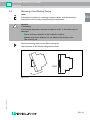
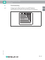
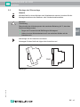
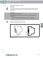
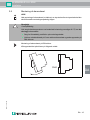
3.2 Mounting of the Warning Device
Mount the warning device on the DIN mounting rail
Clip the device on the DIN mounting rail as follows:
Figure 3.5
Note!
If the device is installed in a housing or switch cabinet, note the mounting
instructions of the housing or switch cabinet manufacturer.
Caution!
Overheating
If the external temperature exceeds a maximum of 60 °C, the device may be
damaged.
■ Ensure sufficient ventilation at the installation location.
■ Maintain a minimum distance of 5 mm between the devices on the
DIN mounting rail.
Click!

233717 2011-05
16 - EN
WARNING DEVICE LAL-SRW
Installation
EN
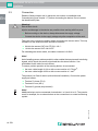
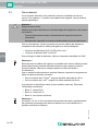
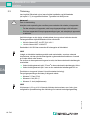
3.3 Connection
Read the Safety chapter and, in particular, the section on Installation and
Commissioning (see chapter 1.7) before connecting the device. Do not remove
the identification plate.
Take care not to reverse the polarity when connecting the sensor cable. The loop
resistance of the extension cable should not exceed
■ 20 Ω for the sensor KVF-104-PF, SLU-103-**.
■ 10 Ω for the sensor NVF-104/34-PF.
For extending the sensor cable, use cable connector LAL-SK2.
The product is a Class II device (with reinforced insulation). Connect the power
supply as follows:
■ Terminal 7: phase (F/L2)
■ Terminal 6: zero (N/L1)
■ Terminal 5: ground (loop terminal)
Warning!
Risk of short circuit
Injuries and damage to the device are possible when working with live parts.
■ Before working on the device, always disconnect the supply voltage.
■ Connect the device to the supply voltage only after completion of the work.
Note!
Avoid installing sensor cables parallel to other cables that may transmit interfering
signals, which impair the sensor signal and thus the alarm function. Use
unshielded 2-wire cable for each sensor.
To ensure perfect operation of the warning device, do not exceed:
■ the max. cable length of 190 m with a cross-section of 0.75 mm
2
.
■ the max. cable length of 250 m with a cross-section of 1 mm
2
.
Note!
Additional relays can be connected via terminals 1 to 3 and 10 to 12. They can be
used, for example, for an external alarm or the connection to a central monitoring
system.

WARNING DEVICE LAL-SRW
Installation
233717 2011-05
EN - 17
EN
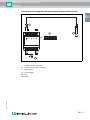
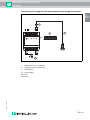
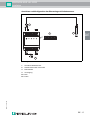
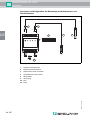
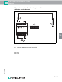
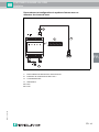
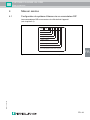
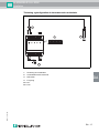
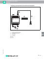
Figure 3.6
Connecting and configuring the warning device with overflow sensor
1 Overflow sensor connection
2 Overflow sensor NVF-104/34-PF
3 DIP switches
4 Power supply
bu blue
bn brown
OFF
ON
13 15 22 23 24
10 11 12123 567
12345678
bubn
230 V AC
3
2
4
1

233717 2011-05
18 - EN
WARNING DEVICE LAL-SRW
Installation
EN
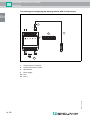
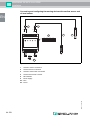
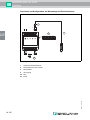
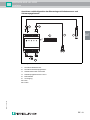
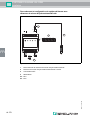
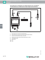
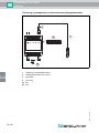
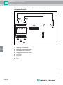
Figure 3.7
Connecting and configuring the warning device with oil level sensor
1 Oil level sensor connection
2 Oil level sensor KVF-104-PF
3 DIP switches
4 Power supply
bu blue
bn brown
OFF
ON
13 15 22 23 24
10 11 12123 567
12345678
230 V AC
2
1
3
4
bubn
Seite laden ...
Seite laden ...
Seite laden ...
Seite laden ...
Seite laden ...
Seite laden ...
Seite laden ...
Seite laden ...
Seite laden ...
Seite laden ...
Seite laden ...
Seite laden ...
Seite laden ...
Seite laden ...
Seite laden ...
Seite laden ...
Seite laden ...
Seite laden ...
Seite laden ...
Seite laden ...
Seite laden ...
Seite laden ...
Seite laden ...
Seite laden ...
Seite laden ...
Seite laden ...
Seite laden ...
Seite laden ...
Seite laden ...
Seite laden ...
Seite laden ...
Seite laden ...
Seite laden ...
Seite laden ...
Seite laden ...
Seite laden ...
Seite laden ...
Seite laden ...
Seite laden ...
Seite laden ...
Seite laden ...
Seite laden ...
Seite laden ...
Seite laden ...
Seite laden ...
Seite laden ...
Seite laden ...
Seite laden ...
Seite laden ...
Seite laden ...
Seite laden ...
Seite laden ...
Seite laden ...
Seite laden ...
Seite laden ...
Seite laden ...
Seite laden ...
Seite laden ...
Seite laden ...
Seite laden ...
Seite laden ...
Seite laden ...
Seite laden ...
Seite laden ...
Seite laden ...
Seite laden ...
Seite laden ...
Seite laden ...
Seite laden ...
Seite laden ...
Seite laden ...
Seite laden ...
Seite laden ...
Seite laden ...
Seite laden ...
Seite laden ...
Seite laden ...
Seite laden ...
Seite laden ...
Seite laden ...
Seite laden ...
Seite laden ...
Seite laden ...
Seite laden ...
Seite laden ...
Seite laden ...
Seite laden ...
Seite laden ...
Seite laden ...
Seite laden ...
Seite laden ...
Seite laden ...
Seite laden ...
Seite laden ...
Seite laden ...
Seite laden ...
Seite laden ...
Seite laden ...
Seite laden ...
Seite laden ...
Seite laden ...
Seite laden ...
Seite laden ...
Seite laden ...
Seite laden ...
Seite laden ...
Seite laden ...
Seite laden ...
Seite laden ...
Seite laden ...
Seite laden ...
-
 1
1
-
 2
2
-
 3
3
-
 4
4
-
 5
5
-
 6
6
-
 7
7
-
 8
8
-
 9
9
-
 10
10
-
 11
11
-
 12
12
-
 13
13
-
 14
14
-
 15
15
-
 16
16
-
 17
17
-
 18
18
-
 19
19
-
 20
20
-
 21
21
-
 22
22
-
 23
23
-
 24
24
-
 25
25
-
 26
26
-
 27
27
-
 28
28
-
 29
29
-
 30
30
-
 31
31
-
 32
32
-
 33
33
-
 34
34
-
 35
35
-
 36
36
-
 37
37
-
 38
38
-
 39
39
-
 40
40
-
 41
41
-
 42
42
-
 43
43
-
 44
44
-
 45
45
-
 46
46
-
 47
47
-
 48
48
-
 49
49
-
 50
50
-
 51
51
-
 52
52
-
 53
53
-
 54
54
-
 55
55
-
 56
56
-
 57
57
-
 58
58
-
 59
59
-
 60
60
-
 61
61
-
 62
62
-
 63
63
-
 64
64
-
 65
65
-
 66
66
-
 67
67
-
 68
68
-
 69
69
-
 70
70
-
 71
71
-
 72
72
-
 73
73
-
 74
74
-
 75
75
-
 76
76
-
 77
77
-
 78
78
-
 79
79
-
 80
80
-
 81
81
-
 82
82
-
 83
83
-
 84
84
-
 85
85
-
 86
86
-
 87
87
-
 88
88
-
 89
89
-
 90
90
-
 91
91
-
 92
92
-
 93
93
-
 94
94
-
 95
95
-
 96
96
-
 97
97
-
 98
98
-
 99
99
-
 100
100
-
 101
101
-
 102
102
-
 103
103
-
 104
104
-
 105
105
-
 106
106
-
 107
107
-
 108
108
-
 109
109
-
 110
110
-
 111
111
-
 112
112
-
 113
113
-
 114
114
-
 115
115
-
 116
116
-
 117
117
-
 118
118
-
 119
119
-
 120
120
-
 121
121
-
 122
122
-
 123
123
-
 124
124
-
 125
125
-
 126
126
-
 127
127
-
 128
128
-
 129
129
-
 130
130
-
 131
131


Pepperl+Fuchs LAL-SRW series Benutzerhandbuch
- Typ
- Benutzerhandbuch
in anderen Sprachen
Verwandte Papiere
-
Pepperl+Fuchs OCT300-M1K-N2 Bedienungsanleitung
-
-
-
-
-
-
-
-
-
Sonstige Unterlagen
-
WIKA IS Barrier Bedienungsanleitung
-
 Stahl ZEX-ALL.BNAMUR1 Bedienungsanleitung
-
SICK BA EN2-2EX-1 Bedienungsanleitung
-
PILZ S1MS Ex Operating Instructions Manual
-
M-Audio MidAir 37 Benutzerhandbuch
-
Bauer FAN Separator Green Bedding Benutzerhandbuch
-
Homa KX...H series Original Instruction Manual
-
Silvercrest SRW 2 A1 Operating Instructions Manual
-
-
