Pepperl+Fuchs MLV12-8-HW-RT/47/65b/95 Bedienungsanleitung
- Typ
- Bedienungsanleitung

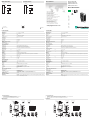
alle Maße in mm
DimensionsAbmessungen
Technische Daten Technical data
Elektrischer Anschluss Electrical connection Adressen/Addresses
Sicherheitshinweise:
• Vor der Inbetriebnahme Betriebsanleitung lesen
• Anschluss, Montage und Einstellung nur durch Fachpersonal
• Kein Sicherheitsbauteil gemäß EU-Maschinenrichtlinie
Security Instructions:
• Read the operating instructions before attempting commissioning
• Installation, connection and adjustments should only be undertaken by specialist personnel
• Not a safety component in accordance with the EU Machinery Directive
all dimensions in mm
www.pepperl-fuchs.com
Pepperl+Fuchs GmbH
68301 Mannheim · Germany
Tel. +49 621 776-4411
Fax +49 621 776-27-4411
Worldwide Headquarters
Pepperl+Fuchs GmbH · Mannheim · Germany
USA Headquarters
Pepperl+Fuchs Inc. · Twinsburg · USA
E-mail: fa-info@us.pepperl-fuchs.com
Asia Pacific Headquarters
Pepperl+Fuchs Pte Ltd · Singapore
Company Registration No. 199003130E
M12x1 M8x1
2
2
1
3
4
6
5
2
4
3
1
53
1
2
4
Stecker um 90° drehbar
Anschlussoptionen
1 Betriebsanzeige grün
2 Schaltanzeige gelb
3 Hell-/Dunkel-Schalter
4 Tastweiteneinsteller
6 optische Achse Sender
5 optische Achse Empfänger
M4 / 4 tief
Festkabel
Gerätestecker M12 Gerätestecker M8
15
10
M12x1
7.5
41.5
5.3
65
5.5
19.5
7
24
ø4.5
11.5
12
49
21.3
31.8
2
M8x1
Reflexions-Lichttaster HW
mit Metallstecker M8, 4-polig
Background evaluation sensor
with M8, 4-pin metal connector
MLV12-8-HW-RT/47/65b/95
Allgemeine Daten
Tastbereich 50 ... 150 mm , einstellbar
Einstellbereich 50 ... 150 mm
Lichtsender LED
Lichtart rot, Wechsellicht , 680 nm
Lichtfleckdurchmesser 4 mm bei Tw 150 mm
Öffnungswinkel 1,5 °
Fremdlichtgrenze
Gleichlicht 30000 Lux
Wechsellicht 5000 Lux
Kenndaten funktionale Sicherheit
MTTFd 650 a
Gebrauchsdauer (TM) 20 a
Diagnosedeckungsgrad (DC) 0 %
Anzeigen/Bedienelemente
Betriebsanzeige LED grün, blinkend im Kurzschlussfall
Funktionsanzeige LED gelb EIN: Sensor erkennt Hintergrund
Bedienelemente Drehschalter für hell/dunkel, Tastweiteneinsteller
Elektrische Daten
Betriebsspannung UB10 ... 30 V DC
Welligkeit max. 10 %
Leerlaufstrom I0
≤
55 mA
Ausgang
Schaltungsart hell-/dunkelschaltend umschaltbar
Signalausgang 2 PNP-Ausgänge, antivalent, kurzschlussfest, verpolsicher, offener Kollektor
Schaltspannung max. 30 V DC
Schaltstrom max. 0,2 A
Spannungsfall Ud
≤
2,5 V DC
Schaltfrequenz f 1000 Hz
Ansprechzeit 0,5 ms
Umgebungsbedingungen
Umgebungstemperatur -40 ... 60 °C (-40 ... 140 °F)
Lagertemperatur -40 ... 75 °C (-40 ... 167 °F)
Mechanische Daten
Schutzart IP67
Anschluss Metallstecker M8, 4-polig, 90° drehbar
Material
Gehäuse Rahmen: Zink-Druckguss, vernickelt
Seitenteile: Kunststoff PC, glasfaserverstärkt
Lichtaustritt Kunststoffscheibe
Masse 60 g
Normen- und Richtlinienkonformität
Normenkonformität
Produktnorm EN 60947-5-2:2007
IEC 60947-5-2:2007
Schock- und Stoßfestigkeit IEC / EN 60068, Halb-Sinus, 40 g je X, Y und Z Richtung
Vibrationsfestigkeit IEC / EN 60068-2-6, Sinus, 10 - 150 Hz, 5 g je X, Y und Z Richtung
Normen UL 508
Zulassungen und Zertifikate
UL-Zulassung cULus
CCC-Zulassung Produkte, deren max. Betriebsspannung
≤
36 V ist, sind nicht zulassungspflichtig und daher nicht mit
einer CCC-Kennzeichnung versehen.
M12x1 M8x1
2
2
1
3
4
6
5
2
4
3
1
53
1
2
4
Connector 90° adjustable position
Connection options:
1 Operating display green
2 Switch state yellow
3 Bright/dark switch
4 Adjuster of detection range
6 Optical axis emitter
5 Optical axis receiver
M4 / 4 deep
Fixed cable
Unit Connector M12 Unit Connector M8
15
10
M12x1
7.5
41.5
5.3
65
5.5
19.5
7
24
ø4.5
11.5
12
49
21.3
31.8
2
M8x1
07/21/2011
Date:
Option:
2
1
3
4
+UB
Q
0 V
Q
/47
13
24
General specifications
Detection range 50 ... 150 mm , adjustable
Adjustment range 50 ... 150 mm
Light source LED
Light type modulated visible red light , 680 nm
Diameter of the light spot 4 mm at Tw 150 mm
Angle of divergence 1.5 °
Ambient light limit
Continuous light 30000 Lux
Modulated light 5000 Lux
Functional safety related parameters
MTTFd 650 a
Mission Time (TM) 20 a
Diagnostic Coverage (DC) 0 %
Indicators/operating means
Operating display LED green, flashes in case of short-circuit
Function display LED yellow ON: sensor detects background
Controls potentiometer for light/dark, detection range adjustment
Electrical specifications
Operating voltage UB10 ... 30 V DC
Ripple max. 10 %
No-load supply current I0
≤
55 mA
Output
Switching type light/dark on switchable
Signal output 2 PNP outputs, complementary, short-circuit protected, reverse polarity protected, open collector
Switching voltage max. 30 V DC
Switching current max. 0.2 A
Voltage drop Ud
≤
2.5 V DC
Switching frequency f 1000 Hz
Response time 0.5 ms
Ambient conditions
Ambient temperature -40 ... 60 °C (-40 ... 140 °F)
Storage temperature -40 ... 75 °C (-40 ... 167 °F)
Mechanical specifications
Protection degree IP67
Connection 4-pin M8 metal connector, 90° rotatable
Material
Housing Frame: nickel plated, die cast zinc,
Laterals: glass-fiber reinforced plastic PC
Optical face Plastic pane
Mass 60 g
Compliance with standards and directives
Standard conformity
Product standard EN 60947-5-2:2007
IEC 60947-5-2:2007
Shock and impact resistance IEC / EN 60068. half-sine, 40 g in each X, Y and Z directions
Vibration resistance IEC / EN 60068-2-6. Sinus. 10 -150 Hz, 5 g in each X, Y and Z directions
Standards UL 508
Approvals and certificates
UL approval cULus
CCC approval Products with a maximum operating voltage of
≤
36 V do not bear a CCC marking because they do
not require approval.
= Hellschaltung
= Dunkelschaltung
= Light on
= Dark on
Option:
2
1
3
4
+UB
Q
0 V
Q
/47
DIN A3 -> DIN A7
Part. No.: 121200 45-2378B
Doc. No.:

Bestimmungsgemäße Verwendung
Bei Reflexions-Lichttaster mit Hintergrundauswertung befinden sich Sender und Empfänger in einem Gehäuse. Durch eine Winkelanord-
nung zwischen Sender und Empfänger (3 Empfaengerelemente) wird eine sichere Detektion von Objekten, durch Auswertung des Hin-
tergrundes erreicht.
Lichttaster mit Hintergrundauswertung bieten sich an, wenn Objekte unabhängig von Bauhöhe und Oberflächenstruktur zu erfassen sind.
Montagehinweise
Die Sensoren können über Durchgangsbohrungen direkt oder über einen Haltewinkel bzw. Klemmkörper (diese sind nicht im Lieferum-
fang enthalten) im Abstand von 50 mm bis 150 mm zum Hintergrund befestigt werden.
Die Untergrundfläche muss plan sein, um Gehäuseverzug beim Festziehen zu vermeiden. Es empfiehlt sich, die Mutter und Schraube
mit Federscheiben zu sichern, um einer Dejustierung des Sensors vorzubeugen.
Justierung
Nach Anlegen der Betriebsspannung leuchtet die LED grün.
Richten Sie den Sensor auf den Hintergrund aus.
Stellen Sie den Tastweiteneinsteller so ein, bis die gelbe LED gerade einschaltet.
Kontrolle Objekterfassung
Das Objekt in den Strahlengang bringen. Wird das Objekt erfasst, erlischt die gelbe LED. Nach Entfernen des Objektes leuchtet die An-
zeige-LED gelb wieder konstant.
Der Hintergrund sollte vorzugsweise hell bzw. weiß sein und darf keine Höhenschwankungen aufweisen. Die Opbekte sollten sich quer
zum Sensor bewegen.
Reinigung
Wir empfehlen in regelmäßigen Abständen die Optikfläche zu reinigen und Verschraubungen, sowie die Anschlussverbindungen zu über-
prüfen.
Appropriate Use
In the reflection light scanner with background evaluation, the sender and recipient are located in one housing. Through the angle arran-
gement between the sender and recipient (3 recipient elements), safe detection of objects is achieved via the background evaluation. The
light scanner with background evaluation is best used when objects can be detected independent of headroom and surface structure.
Installation Instructions
The sensors can be attached via the through bore-hole directly or via a bracket/clamp body (these are not included in the shipment) at a
distance of 50 mm to 150 mm from the background. The subsurface must be smooth in order to prevent the housing from warping when
it is tightened. It is recommended that the nut and screw be safetied with a spring washer to guard against maladjustment of the sensor.
Adjustment
After feeding the operating voltage, the LED display turns green. Align the sensor with the background. Set the distance adjust key until
the yellow LED display turns on.
Object Detection Controlling
Move the object into the beam path. Once the object is detected, the yellow LED display fades out. After the object is removed, the LED
display remains yellow. The background should be preferably bright or white and may not show height fluctuations. The objects should
move cross-wise toward the sensor.
Cleaning
We recommend that you clean the optical surface on a regular basis and check the fittings and connection parts.
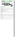
MLV12-8-HW...
x
Y
0 50 100 150
6
4
2
0
Minimale Objekthöhe
Hauteur minimale d'objet
Altezza minima oggetto
Minimum object height
Mínima altura del objeto
X [mm]
Objekthöhe, Object height, Hauteur d'obje,
Altura del objeto, Altezza oggetto
Y [mm]
90 %/ 6 %
90 %/ 90 %
6 %/ 6%
6 %/ 90 %
Beschreibung/Desciption
-
 1
1
-
 2
2


Pepperl+Fuchs MLV12-8-HW-RT/47/65b/95 Bedienungsanleitung
- Typ
- Bedienungsanleitung
in anderen Sprachen
Verwandte Artikel
-
Pepperl+Fuchs ML100-8-HW-350-RT/103/115 Bedienungsanleitung
-
-
-
-
-
-
-
-
-