
DEUTSCH
DEUTSCH
Refl exions-Lichttaster
mit Laserlicht
Betriebsanleitung
Sicherheitshinweis
Kennzeichnung:
II 3G EX nA op is IIB T4 Gc X
II 3D EX tc IIIB T135°C Dc IP67 X
–10°C < Ta < +50°C
Geräte entsprechen der Schutzart für Betriebsmittel zur Verwendung
in explosionsgefährdeten Bereichen mit brennbaren, nichtleitfähigem
Staub.
Vor der Inbetriebnahme die Betriebsanleitung und die Montageanleitung
lesen.
Anschluss, Montage und Einstellung nur durch Fachpersonal.
Die Strahlung des Sendelichtes darf nicht durch zusätzliche optische
Bauteile fokussiert werden.
Trennen Sie die elektrischen Anschlüsse des Gerätes nur in spannungs-
freiem Zustand, denn beim Trennen von Strom führenden Teilen können
Funken entstehen. Dadurch besteht im explosionsgefährdeten Bereich
Lebensgefahr!
Gerät bei der Inbetriebnahme vor Feuchte und Verunreinigung schützen.
Kein Sicherheitsbauteil gemäß EU-Maschinenrichtlinie.
ACHTUNG, besondere Bedingungen!
1 Wählen Sie die Montageposition so, dass die Frontscheibe keiner
UV-Strahlung (z. B. Sonnenlicht) ausgesetzt ist. UV-Strahlung kann die
Lebensdauer und die Beständigkeit der Gerätefrontscheibe reduzieren.
A
1
2 Das Gerät ist so zu errichten, dass nicht mit einer mechanischen
Beschädigung zu rechnen ist. Das Schutzgehäuse ist kundenseitig zu
erstellen (nicht im Lieferumfang enthalten, siehe Zeichnung).
3 NICHT UNTER SPANNUNG TRENNEN!
Die mitgelieferte Steckersicherung muss angebracht werden, damit
ein Trennen des Steckers ohne Werkzeug verhindert wird.
Bestimmungsgemäße Verwendung
Richtlinienkonformität Explosionsschutz:
EG-Richtlinie 94/9/EG.
Die Geräte entsprechen der Kategorie 3D / 3G und können in den
explosionsgefährdeten Bereichen „Zone 22: nichtleitende Stäube“ und
„Zone 2“ eingesetzt werden.
Der Refl exions-Lichttaster WT9L ist ein optoelektronischer Sensor und
wird zum optischen, berührungslosen Erfassen von Sachen, Tieren und
Personen eingesetzt.
Inbetriebnahme
1 Q: dunkelschaltend, bei Lichtunterbrechung Ausgang HIGH.
Q: hellschaltend, bei Lichtempfang Ausgang HIGH.
Gewünschte Betriebsart laut
B anschließen (Q/Q).
2 Leitungsdose spannungsfrei aufstecken, festschrauben und Steckersi-
cherung anbringen. Für Anschluss in
B gilt:
brn = braun, blu = blau, blk = schwarz, wht = weiß.
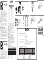
3 Lichttaster an geeignete Halter (z. B. SICK-Haltewinkel) mit 2
Schrau ben montieren. Bewegungsrichtung des Objektes relativ zum
Taster einhalten. Lichttaster an Betriebsspannung anlegen (siehe
Typenaufdruck). Einsatzbedingungen wie Tastweite, Objektgröße und
Hintergrundeinfl uss überprüfen und mit der Kennlinie im Diagramm
vergleichen (x = Tastweite, y = Übergangsbereich zwischen einge-
stellter Tastweite und sicherer Hintergrundausblendung, (z) in % der
Tastweite).
4 Einstellung Tastweite: Drehknopf auf Max. stellen. Objekt positionie-
ren, Lichtfl eck auf Objekt ausrichten, sichtbarer roter Sendelichtfl eck
auf Objekt erkennbar. Grüne und gelbe LEDs müssen permanent
leuchten. Leuchtet die gelbe LED nicht oder blinkt sie, Lichttaster neu
justieren, reinigen bzw. Einsatzbedingungen prüfen. Objekt entfernen,
gelbe LED muss erlöschen. Erlischt sie nicht oder blinkt sie, wird der
Hintergrund erfasst. Tastweite am Drehknopf so weit reduzieren, bis
die gelbe LED erlischt.
Wartung
SICK-Lichtschranken sind wartungsfrei.
Wir empfehlen, in regelmäßigen Abständen
– die optischen Grenzfl ächen zu reinigen,
– Verschraubungen, Steckverbindungen und Justage zu überprüfen.
Veränderungen an Geräten dürfen nicht vorgenommen werden.
B
2
3a
4
WT9L
12
22
40
20
3
3
1,5
20
7, 5
11
25
125
150
12
6
8
10
4
0
2
6%/90%
18%/90%
90%/90%
50 75
100
y [%]
x [mm]
WT9L
WT9L-P330S02
WT9L-P330S02
------------------------------------------------------------- 8015063.WA21 0612 GO ---------------------------------------------------------
---------------------------------------------------------------------------------------------------------------------------------------------------------------------------------------------------
1
L+
Q
Q
4
2
3
M
brn
wht
blu
blk
ENGLISH
ENGLISH
Photoelectric Retro-refl ective Sensor
with laser light
Operating Instructions
Safety Specifi cations
Marking:
II 3G EX nA op is IIB T4 Gc X
II 3D EX tc IIIB T135°C Dc IP67 X
–10°C < Ta < +50°C
Devices correspond to the enclosure rating for electrical apparatus for
use in the presence of combustible, non-conductible dust.
Read the operating instructions and the assembly instructions before
starting operation.
Connection, assembly and settings only by competent technicians.
The light beam of the LED may not focused with additional optical parts.
Disconnect the electrical connections of the device only if tension-free
because the disconnection of the live parts can cause sparks. Thereby it
exists danger of life in the potentially explosive atmosphere!
Protect the device against moisture and soiling when operating.
No safety component in accordance with EU machine guidelines.
CAUTION: Use of controls or adjustments or performance of procedures
other than those specifi ed herein may result in hazardous radiation
exposure.
CAUTION, special conditions!
1 Select the position for mounting that the front lens does not receive
any UV radiation (e.g. sun light). The UV radiation can reduce the
service life time and the resistance of the front lens.
2 The device has to be mounted so that there can be no hazard caused
by mechanical damage. The protection housing has to be mounted by
the customer (not included in the scope of delivery, see drawing).
3 Do not disconnect the plug while power is switched on! The included
connector protection must be fi xed to prevent disconnection without a
tool.
Proper Use
Directive relevant conformity explosion prevention: directive 94/9/EC.
The devices correspond to the category 3D / 3G and can be used in
potentially explosive atmosphere “zone 22, non-conductible dust” and
“zone 2”.
The WT9L photoelectric retro-refl ective sensor is an optoelectronic sen-
sor and is used for contactless detection of objects, animals and people.
Starting Operation
1 : dark-switching; if light interrupted, output HIGH.
Q: light-switching; if light received, output HIGH.
Select desired operating mode externally and connect as per connec-
tion diagram
B (Q/Q).
2 The following apply for the connection in B :
brn = brown, blu = blue, blk = black, wht = white. Connect cables and
fi x the connector protection.
3 The sensor has to be mounted at least with two screws to suitable
holders (e.g. SICK mounting bracket). Maintain direction in which
object moves relative to sensor. Connect photoelectric retro-refl ective
sensor to operating voltage (see type label). Check application condi-
tions such as sensing distance, size and refl ectance of object to be
detected as well as of background, and compare with characteristic in
diagram. (x = sensing distance, y = transition range between set sens-
ing distance and reliable background suppression (z) in % of sensing
distance).
4 Adjustment of sensing distance: Set sensing distance adjuster to max.
Position object. Align light spot to object, red sender light visible on
object. Green and yellow LEDs must light continuously. If the yellow
LED does not light or blink, readjust the photoelectric retro-refl ective
sensor, clean it and/or check the application conditions. Remove the
object; the yellow LED must switch off . If it does not switch off or blink,
the background is detected. Reduce the sensing distance with sensing
distance adjuster until the yellow LED switches off .
Maintenance
SICK photoelectric sensors do not require any maintenance.
We recommend that you clean the optical interfaces and check the screw
connections, plug-in connections and the adjustment at regular intervals.
Modifi cations of devices may not be made.
Australia
Phone +61 3 9497 4100
Belgium/Luxembourg
Phone +32 (0)2 466 55 66
Brasil
Phone +55 11 3215-4900
Canada
Phone +1(952) 941-6780
Ceská Republika
Phone +420 2 57 91 18 50
China
Phone +852-2763 6966
Danmark
Phone +45 45 82 64 00
Deutschland
Phone +49 211 5301-301
España
Phone +34 93 480 31 00
France
Phone +33 1 64 62 35 00
Great Britain
Phone +44 (0)1727 831121
India
Phone +91–22–4033 8333
Israel
Phone +972-4-999-0590
Italia
Phone +39 02 27 43 41
Japan
Phone +81 (0)3 3358 1341
Magyarország
Phone +36 1 371 2680
Nederlands
Phone +31 (0)30 229 25 44
Österreich
Phone +43 (0)22 36 62 28 8-0
Norge
Phone +47 67 81 50 00
Polska
Phone +48 22 837 40 50
România
Phone +40 356 171 120
Russia
Phone +7 495 775 05 30
Schweiz
Phone +41 41 619 29 39
Singapore
Phone +65 6744 3732
Slovenija
Phone +386 (0)1-47 69 990
South Africa
Phone +27 11 472 3733
South Korea
Phone +82-2 786 6321/4
Suomi
Phone +358-9-25 15 800
Sverige
Phone +46 10 110 10 00
Taiwan
Phone +886 2 2375-6288
Türkiye
Phone +90 216 528 50 00
United Arab Emirates
Phone +971 4 8865 878
USA/México
Phone +1(952) 941-6780
BZ int37
Please find detailed addresses and additional representatives and agencies in
all major industrial nations at www.sick.com
wavelength: 655nm
pulse length: 5us
max.output<4,0mW
LASER CLASS 2
INTO BEAM
DO NOT STARE
LIGHT
LASER-
LASER APERTURE
No. 50, July 2001
to laser notice
1040.11 except for
deviations pursuant
21 CFR1040.10 and
Complies with
EN60825-1:2001
/AM.2: 2001
IEC 60825-1
wavelength: 655nm
pulse length: 5us
max.output<4,0mW
LASER CLASS 2
INTO BEAM
DO NOT STARE
LIGHT
LASER-
LASER APERTURE
No. 50, July 2001
to laser notice
1040.11 except for
deviations pursuant
21 CFR1040.10 and
Complies with
EN60825-1:2001
/AM.2: 2001
IEC 60825-1
1 Mitte Optikachse, Sender
Centre of optical axis, sender
2 Mitte Optikachse, Empfänger
Centre of optical axis, receiver
3 Durchgangsbohrung ∅ 3,2 mm
Mounting hole ∅ 3,2 mm
4 Betriebsanzeige grün; Empfangsanzeige gelb
Power indicator green;
LED signal strength indicator yellow
5 M8-Stecker, 4-polig
Plug M8, 4-pin
6 Tastweiteneinsteller
Sensing distance adjustment
1
3
3
4 4
6
5
2
WT9L 9118537
II3G EX nA op is IIB T4 Gc X
II3D EX tc IIIB T135°C Dc IP67 X
–10°C < Ta < +50°C
Technical data Technische Daten
Sensing distance Tastweite 30…150 m
1)
Light spot diamter/
focusing point
Lichtfleckdurchmesser/
Fokuslage
< 0,5 mm / 60 mm
Supply voltage V
s
Versorgungsspannung U
v
10…30 V DC
2)
Output current I
max
Ausgangsstrom I
max
100 mA
Switching frequency Schaltfrequenz 1000/s
Response time Ansprechzeit < 0,6 ms
Enclosure rating Schutzart IP 67
Protection class Schutzklasse III
Circuit protection
3)
Schutzschaltungen
3)
A, B, C,
Ambient operating temperature
4)
Betriebstemperatur
4)
–10 <Ta< +50°C
1)
Object with 90% remission
(based on standard
white to DIN 5033)
2)
Limit values, ripple max. 5 V
ss
3)
A = V
s
connections reverse-
polarity protected
B = Outputs short-
circuit protected
C = Interference pulse
suppression
4)
Do not stack devices
1)
Objekt mit 90% Remission
(bezogen auf Standard
Weiß nach DIN 5033)
2)
Grenzwerte,
Restwelligkeit max. 5 V
ss
3)
A = U
v
-Anschlüsse
verpolsicher
B = Ausgänge kurz-
schlussfest
C = Störimpuls-
unterdrückung
4)
Geräte nicht stapeln
EC Declaration of conformity
The undersigned, representing the following manufacturer
SICK AG
Erwin-Sick-Straße 1
79183 Waldkirch
Germany
herewith declares, that the products of the product family
W.9L-..S..(ATEX)
are in conformity with the provisions of the following EC directives (including all applicable amendments),
and that the standards and/or technical specifications referenced below have been applied.
II 3G EX nA op is IIB T4 Gc X
II 3D EX tc IIIB T135°C Dc IP67 X
-10°C < Ta < +50°C
Used directives and standards:
Directive or standard Title or short decription Issued
Directive 2004/108/EC EMC-Directive 2004-12
Directive 1994/9/EC Equipement intended for use in potentially
explosive atmosphere (ATEX)
1994-9
EN 60947-5-2 Low-Voltage Switchgear and Controlgear 2007-12
EN 60079-0 Electrical apparatus for explosive gas atmospheres
– part 0: General requirements
2009-08
EN 60079-15 Electrical apparatus for explosive gas atmospheres 2010-05
EN 60079-28 Electrical apparatus for explosive gas atmospheres 2007-03
EN 60079-31 Electrical apparatus for explosive gas atmospheres 2009-12
3b
More representatives and agencies at www.sick.com ∙ Subject to change
without notice ∙ The specifi ed product features and technical data do not
represent any guarantee.
Weitere Niederlassungen fi nden Sie unter www.sick.com ∙ Irrtümer
und Änderungen vorbehalten ∙ Angegebene Produkteigenschaften und
technische Daten stellen keine Garantieerklärung dar.
-
 1
1

in anderen Sprachen
- English: SICK WT9L Operating instructions
Verwandte Artikel
-
SICK WT18X-3P920 Bedienungsanleitung
-
-
-
-
-
-
SICK WL18X-3P930 Bedienungsanleitung
-
-
-