
ENGLISH
Photoelectric proximity switch
energetic
Operating instructions
Safety notes
> Marking:
II 3G EX nA op is IIB T4 Gc X
II 3D EX tc IIIB T135 °C Dc X
–20 °C < Ta < +50 °C
> It corresponds to the enclosure rating for electrical apparatus for use in
the presence of combustible, non-conductible dust.
> Read the operating instructions before starting operation.
> Connection, assembly, and settings only by competent technicians.
> The light beam of the LED may not focused with additional optical parts.
> Disconnect the electrical connections of the device only if tension-free
because the disconnection of the live parts can cause sparks. Thereby
it exists danger of life in the potentially explosive atmosphere.
> Protect the device against moisture and soiling when operating.
> No safety component in accordance with EU machine guidelines.
> UL: Only for use in applications in accordance with NFPA 79.
These devices shall be protected by a 1 A fuse suitable for 30 V DC.
Adapters listed by UL with connection cables are available. Enclosure type 1.
Caution, special condition
> Select the position for mounting that the front lens does not receive any
UV radiation (e. g. sun light). The UV radiation can reduce the service life
time and the resistance of the front lens.
> The device has to be mounted so that there can be no hazard caused by
mechanical damage.
> DO NOT DISCONNECT THE PLUG WHILE POWER IS SWITCHED ON!
> The connector protector provided must be tted to ensure that the con-
nector cannot be disconnected without a tool (if included with delivery).
> When mounting sensors with a metallic protective housing, it must be
ensured that there is a conductive connection.
Equipotential bonding should be considered at the mounting location.
> Exceeding tensile loading at the cable is to avoid.
Proper Use
> Directive relevant conformity explosion prevention:
Directive 2014 / 34 / EU.
> The devices correspond to the category 3D / 3G and can be used in
potentially explosive atmosphere “zone 22, non-conductible dust” and
“zone 2”.
> The WTE27X-3 photoelectric proximity switch is an optoelectronic sensor
and is used for optical, non-contact detection of objects, animals and
persons.
Starting operation
1 The devices WTE27X-3 have complementary switching outputs:
Only WTE27-3P / -3F (PNP, load → M):
Q: dark-switching, object is not detected, output HIGH,
Q: light-switching, object is detected, output HIGH.
Only WTE27-3N (NPN, load → L+):
Q: dark-switching, object is not detected, output LOW,
Q: light-switching, object is detected, output LOW.
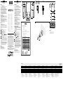
Connected desired operating mode in accordance with B .
The following apply for connection in B : brn = brown, blk = black,
wht = white, blu = blue.
Connect cable and secure tension-free.
2 The sensor have to be mounted at least with two screws to suitable
holders (e. g. SICK mounting bracket).
3 Check the conditions of the application. Sensing distance and remis-
sion of the object have to be checked with the corresponding sensing
distance. An object can be detected in front of a background only when
the remission of the object is signicantly higher than the remission of
the background or when the distance between object and background
is big enough.
The sensitivity (sensing distance) will be adjusted with the potentio-
meter. Turn to the right: increase of sensitivity (sensing distance), turn
to the left: decrease of sensitivity (sensing distance). After the adjust-
ment of the sensing distance remove the object from the light beam,
the background will be suppressed and the output changes (see
graph 1). The sensor is adjusted and ready for operation.
Maintenance
SICK light barriers are maintenance-free.
We recommend doing the following regularly:
– clean the external lens surfaces
– check the screw connections and plug-in connections.
No modications may be made to devices.
DEUTSCH
Reexions-Lichttaster
energetisch
Betriebsanleitung
Sicherheitshinweise
> Kennzeichnung:
II 3G EX nA op is IIB T4 Gc X
II 3D EX tc IIIB T135 °C Dc X
–20 °C < Ta < +50 °C
> Geräte entsprechen der Schutzart für Betriebsmittel zur Verwendung
in explosionsgefährdeten Bereichen mit brennbarem nichtleitfähigem
Staub.
> Vor der Inbetriebnahme die Betriebsanleitung lesen.
> Anschluss, Montage und Einstellung nur durch Fachpersonal.
> Die Strahlung des Sendelichts darf nicht durch zusätzliche optische
Bauteile fokussiert werden.
> Trennen Sie die elektrischen Anschlüsse des Geräts nur in spannungs-
freiem Zustand, denn beim Trennen von stromführenden Teilen können
Funken entstehen. Dadurch besteht im explosionsgefährdeten Bereich
Lebensgefahr.
> Gerät bei Inbetriebnahme vor Feuchte und Verunreinigung schützen.
> Kein Sicherheitsbauteil gemäß EU-Maschinenrichtlinie.
> UL: Nur zur Verwendung in Anwendungen gemäß NFPA 79.
Diese Geräte müssen mit einer für 30 V DC geeigneten 1 A-Sicherung
abgesichert werden. Von UL gelistete Adapter mit Anschlusskabeln sind
verfügbar. Enclosure type 1.
Achtung, besondere Bedingung
> Wählen Sie die Montageposition so, dass die Frontscheibe keiner
UV-Strahlung (z. B. Sonnenlicht) ausgesetzt ist.
UV-Strahlung kann die Lebensdauer und die Beständigkeit der
Gerätefrontscheibe reduzieren.
> Das Gerät ist so zu errichten, dass nicht mit einer mechanischen
Beschädigung zu rechnen ist.
> NICHT UNTER SPANNUNG TRENNEN!
> Die mitgelieferte Steckersicherung muss angebracht werden, damit
ein Trennen des Steckers ohne Werkzeug verhindert wird (wenn im
Lieferumfang enthalten).
> Bei der Befestigung ist auf eine leitende Verbindung zu achten.
Der Errichtungsort ist in den Potentialausgleich einzubinden.
> Übermäßige Zugbelastung am Kabel ist zu vermeiden
Bestimmungsgemäße Verwendung
> Richtlinienkonformität Explosionsschutz: Richtlinie 2014 / 34 / EU.
> Die Geräte entsprechen der Kategorie 3D / 3G und können in den
explosionsgefährdeten Bereichen „Zone 22: nichtleitende Stäube“ und
„Zone 2“ eingesetzt werden.
> Der Reexions-Lichttaster WTE27X-3 ist ein optoelektro nischer Sensor
und wird zum optischen, berührungslosen Erfassen von Sachen, Tieren
und Personen eingesetzt.
Inbetriebnahme
1 Die Geräte WTE27X-3 haben antivalente Schaltausgänge:
Nur WTE27-3P / -3F (PNP, Last → M):
Q: dunkelschaltend, Objekt wird nicht erkannt, Ausgang HIGH,
Q: hellschaltend, Objekt wird erkannt, Ausgang HIGH.
Nur WTE27-3N (NPN, Last → L+):
Q: dunkelschaltend, Objekt wird nicht erkannt, Ausgang LOW,
Q: hellschaltend, Objekt wird erkannt, Ausgang LOW.
Gewünschte Betriebsart gemäß B anschließen.
Für Anschluss in B gilt: brn = braun, blk = schwarz, wht = weiß,
blu = blau.
Leitungen nur im spannungsfreien Zustand anschließen.
2 Sensor muss mit mindestens zwei Schrauben an geeignete Halter
angeschraubt werden (z. B. SICK-Haltewinkel).
3 Einsatzbedingungen prüfen: Schaltabstand und Remissionsvermögen
des Objektes mit den dazugehörigen Schaltabständen abgleichen.
Dabei kann ein Objekt vor einem Hintergrund nur detektiert werden,
wenn das Remissionsvermögen des Objektes deutlich größer ist
als das Remissionsvermögen des Hintergrundes oder der Abstand
zwischen Objekt und Hintergrund ausreichend groß ist.
Mit dem Potentiometer wird die Empndlichkeit (Schaltabstand)
eingestellt. Drehung nach rechts: Erhöhung der Empndlichkeit
(Schaltabstand), Drehung nach links: Verringerung der Empndlichkeit
(Schaltabstand). Nach dem die Empndlichkeit eingestellt worden ist,
wird das Objekt aus dem Strahlengang entfernt, der Hintergrund wird
dabei ausgeblendet und der Schaltausgang ändert sich (siehe
Grak 1). Sensor ist eingestellt und betriebsbereit.
Wartung
SICK-Lichtschranken sind wartungsfrei.
Wir empfehlen, in regelmäßigen Abständen
– die optischen Grenzächen zu reinigen,
– Verschraubungen und Steckverbindungen zu überprüfen.
Veränderungen an Geräten dürfen nicht vorgenommen werden.
WTE27X-3
------------------------------------------------------- 8016587.11HQ 0219 COMAT -----------------------------------------------------
1
A
WTE27X-3P1861
II 3G EX nA op is IIB T4 Gc X
II 3D EX tc IIIB T135 °C Dc X
–20 °C < Ta < +50 °C
Sensing range max. Schaltabstand max. Distance de commutation maxi. Distância de comutação máx. Distanza di commutazione massima Distancia de conmutación máx.
检测范围, 最大 スイッチ間隔、最大値
Расстояние срабатывания макс. 20 ... 400 mm
1)
Supply voltage V
S
Versorgungsspannung U
V
Tension d'alimentation U
V
Tensão de força U
V
Tensione di alimentazione U
V
Tensión de alimentación U
V
电源电压 U
V
供給電圧 U
V
Напряжение питания U
V
10 ... 30 V DC
2)
Output current I
max.
Ausgangsstrom I
max.
Courant de sortie I
max.
Corrente de saída I
max.
Corrente di uscita max. I
max.
Corriente de salida I
max.
输出电流 I
max.
最大出力電流 I
max.
Выходной ток I
макс.
100 mA
Max. switching frequency Schaltfolge max. Cadence de commutation maxi Seqüência de ligações máx. Sequenza di commutazione max. Secuencia de maniobras max.
最小信号序列
最小信号シーケンス
Частота срабатывания макс. 350 / s
3)
Response time Ansprechzeit Temps de réponse Tempo de reação Tempo di risposta Tiempo de reacción
触发时间
応答時間
Время отклика
1.5 ms
4)
Enclosure rating Schutzart Type de protection Tipo de proteção Tipo di protenzione Tipo de protección 保护种类
保護等級
Класс защиты
IP 67
Protection class Schutzklasse Classe de protection Classe de proteção Classe di protezione Protección clase
保护级别
保護クラス
Класс защиты
5)
Circuit protection Schutzschaltungen Circuits de protection Circuitos protetores Commutazioni di protezione Circuitos de protección
保护电路 保護回路
Схемы защиты
A, B, C
6)
Ambient operating temperature Betriebsumgebungstemperatur Température ambiante de fonctionnement Temperatura ambiente operacional Temperatura di lavoro Temperatura ambiente de servicio
工作环境-温度 使用周囲温度
Диапазон рабочих температур
–20 °C ... +50 °C
1)
Object 90 % reflection according to DIN 5033
2)
Limits
Ripple max. 0.4 V
PP
3)
With light / dark ratio 1:1
4)
Signal transit time with resistive load
5)
Reference voltage < 50 V DC
6)
A = V
S
connections reverse polarity protected
B = Output Q and – short-circuit protected
C = Interference pulse suppression
1)
Objekt 90 % Remission nach DIN 5033
2)
Grenzwerte
Restwelligkeit max. 0,4 V
SS
3)
Bei Hell- / Dunkelverhältnis 1:1
4)
Signallaufzeit bei ohmscher Last
5)
Bemessungsspannung < 50 V DC
6)
A = U
V
-Anschlüsse verpolsicher
B = Ausgang Q und – kurzschlussgeschützt
C = Störimpulsunterdrückung
1)
Objet Luminance de 90 % selon DIN 5033
2)
Valeurs limites
Ondulation résiduelle maxi 0,4 V
SS
3)
Pour un rapport clair / sombre de 1:1
4)
Temps de propagation du signal sous charge ohmique
5)
Tension de calcul < 50 V c.c.
6)
A = Raccordements U
V
protégés contre les inversions de polarité
B = Sorties Q et – protégées contre les courts-circuits
C = Suppression des impulsions parasites
1)
Objeto: 90 % de remissão segundo DIN 5033
2)
Valores limite
Ondulação residual máx. 0,4 V
SS
3)
Com relação claro / escuro 1:1
4)
Tempo de transição do sinal com carga ôhmica
5)
Tensão de dimensionamento < 50 V DC
6)
A = Conexões U
V
protegidas contra inversão de polos
B = Saídas Q e – protegidas
C = Supressão de impulsos parasitas
1)
Oggetto 90 % remissione sec. DIN 5033
2)
Valori limite
Ondulatione residua max. 0,4 V
SS
3)
Con rapporto chiaro / scuro 1:1
4)
Tempo di transito segnale con carico ohmico
5)
Tensione di taratura < 50 V DC
6)
A = U
V
-collegamenti con protez. contro inversione di poli
B = Uscita Q e – a prova di corto circuito
C = Soppressione impulsi di disturbo
1)
Objeto 90 % de remission en base a DIN 5033
2)
Valores límite
Ondulación residual max. 0,4 V
SS
3)
Con una relación claro / oscuro 1:1
4)
Tiempo de propagación de la señal con carga óhmica
5)
Tensión tolerable < 50 V DC
6)
A = Conexiones U
V
a prueba de inversión de polaridad
B = Salida Q y – protegida contra cortocircuito
C = Represión de impulso de interferencia
1)
90 % 漫反射比物体按照 DIN 5033
2)
操作电流:
残余纹波最大为 0,4 V
SS
3)
亮 / 暗比 1:1
4)
电阻性负载时,传感器检测到变化时输出信号的转换时间
5)
限定电压DC 50 V
6)
A = U
V-
接头防反接
B = 输出端 Q 和 (已采取短路保护措施)
C = 消除干扰脉冲
1)
対象物 90 % の反射率 DIN 5033 に準拠
2)
限界値:
最大リップル電圧 0,4 V
SS
3)
明暗比率 1:1の場合
4)
抵抗負荷における信号遷移時間
5)
定格電圧 DC 50 V
6)
A = U
V
接続 逆接保護
B = 出力回路 Q および 短絡保護
C = 干渉パルス制御
1)
Сканируемый объект – ремиссия 90 %
(относительно стандартного белого по DIN 5033)
2)
Предельные значения, остаточная волнистость макс. 0,4 В
SS
3)
Соотношение светлых и темных участков изображения 1:1
4)
Продолжительность сигнала при омической нагрузке
5)
Расчетное напряжение DC 50 V
6)
A = U
V
-подключения с защитой от перепутывания полюсов
B = Выход Q и с защитой от короткого замыкания
C = Подавление импульсных помех
16.6
(0.65)
31.5
(1.24)
70
(2.76)
18
(0.71)
76.5
(3.01)
15
(0.59)
70.4
(2.77)
40
(1.57)
31.4
(1.24)
112.3
(4.42)
92
(3.62)
54.5
(2.15)
8
(0.31)
brn
blk
wht
blu
L+
Q
Q
M
(PNP)
(NPN)
Q
Q
1
0
1
0
1
0
1
0
2 3
0 100
(3.94)
200
(7.87)
300
(11.81)
400
(15.75)
Distance in mm (inch)
150250
20 400
60 330
Sensing range
Sensing range on black, 6 % remission
Sensing range on gray, 18 % remission
Sensing range on white, 90 % remission
B
brn
blk
wht
blu
L+
Q
Q
M
1
4
2
3
More representatives and agencies at www.sick.com ∙ Subject to change
without notice ∙ The specied product features and technical data do not
represent any guarantee.
Weitere Niederlassungen nden Sie unter www.sick.com ∙ Irrtümer
und Änderungen vorbehalten ∙ Angegebene Produkteigenschaften und
technische Daten stellen keine Garantieerklärung dar.
Plus de représentations et d’agences à l’adresse www.sick.com ∙ Sujet à
modication sans préavis ∙ Les caractéristiques de produit et techniques
indiquées ne constituent pas de déclaration de garantie.
Para mais representantes e agências, consulte www.sick.com ∙ Alterações
poderão ser feitas sem prévio aviso ∙ As características do produto e os
dados técnicos apresentados não constituem declaração de garantia.
Altri rappresentanti ed agenzie si trovano su www.sick.com ∙ Contenuti
soggetti a modiche senza preavviso ∙ Le caratteristiche del prodotto e i dati
tecnici non rappresentano una dichiarazione di garanzia.
Más representantes y agencias en www.sick.com ∙ Sujeto a cambio sin
previo aviso ∙ Las características y los datos técnicos especicados no
constituyen ninguna declaración de garantía.
欲了解更多代表机构和代理商信息,请登录 www.sick.com ∙
如有更改 , 不另行通知 ∙ 对所给出的产品特性和技术参数
的正确性不予保证。
その他の営業所は www.sick.com よりご覧ください ∙ 予告なし
に変更されることがあります ∙ 記載されている製品機能およ
び技術データは保証を明示するものではありません。
EU Declaration of conformity
The undersigned, representing the following manufacturer
SICK AG
Erwin-Sick-Straße 1
79183 Waldkirch
Germany
herewith declares, that the products of the product family
W.24-2…..S.. (ATEX)
are in conformity with the provisions of the following directives (including all applicable
amendments), and that the standards and/or technical specifications referenced below have
been applied.
II 3G Ex nA op is IIB T4 Gc X
II 3D Ex tc IIIB T135 °C Dc X
-20 °C < Ta < +50 °C
Used directives and standards:
Directives
Official Journal
of the EU L96
Title or short description Issued
Directive 2014/30/EU EMC-Directive – electromagnetic compatibility 2014 – 02
Directive 2014/34/EU 2014 – 02
EN 60947 – 5 – 2 2007 – 12
EN 60079 – 0 Explosive atmospheres – part 0: Equipment
– General requirements
2012 – 08
EN 60079 – 15 2010 – 05
EN 60079 – 0 / A11 Explosive atmospheres – part 0: Equipment
– General requirements
Explosive atmospheres – part 15: Equipment
protection by type of protection „n“
2013 – 11
EN 60079 – 28 Explosive atmospheres - Part 28: Protection of
equipment and transmission systems using optical
radiation
2007 – 03
EN 60079 – 31 Explosive atmospheres - Part 31: Equipment dust
ignition protection by enclosure "t"
2009 – 12
Equipment and protective systems intended for
use in potentially explosive atmosphere
Standards
Title or short description Issued
Low voltage switchgear and controlgear – part 5-6:
Control circuit devices and switching elements
– proximity switches
WTE27X-3P11xx WTE27X-3N11xx WTE27X-3P34xx
WTE27X-3P12xx WTE27X-3N12xx
WTE27X-3P17xx WTE27X-3N17xx
WTE27X-3P18xx WTE27X-3N18xx
SICK AG, Erwin-Sick-Strasse 1, D-79183 Waldkirch
BZ int48
Please find detailed addresses and further locations in all major industrial
nations at www.sick.com
Australia
Phone +61 (3) 9457 0600
Austria
Phone +43 (0) 2236 62288-0
Belgium/Luxembourg
Phone +32 (0) 2 466 55 66
Brazil
Phone +55 11 3215-4900
Canada
Phone +1 905.771.1444
Czech Republic
Phone +420 2 57 91 18 50
Chile
Phone +56 (2) 2274 7430
China
Phone +86 20 2882 3600
Denmark
Phone +45 45 82 64 00
Finland
Phone +358-9-25 15 800
France
Phone +33 1 64 62 35 00
Germany
Phone +49 (0) 2 11 53 01
Hong Kong
Phone +852 2153 6300
Hungary
Phone +36 1 371 2680
India
Phone +91-22-6119 8900
Israel
Phone +972-4-6881000
Italy
Phone +39 02 27 43 41
Japan
Phone +81 3 5309 2112
Malaysia
Phone +603-8080 7425
Mexico
Phone +52 (472) 748 9451
Netherlands
Phone +31 (0) 30 229 25 44
New Zealand
Phone +64 9 415 0459
Norway
Phone +47 67 81 50 00
Poland
Phone +48 22 539 41 00
Romania
Phone +40 356-17 11 20
Russia
Phone +7 495 283 09 90
Singapore
Phone +65 6744 3732
Slovakia
Phone +421 482 901 201
Slovenia
Phone +386 591 78849
South Africa
Phone +27 (0)11 472 3733
South Korea
Phone +82 2 786 6321
Spain
Phone +34 93 480 31 00
Sweden
Phone +46 10 110 10 00
Switzerland
Phone +41 41 619 29 39
Taiwan
Phone +886-2-2375-6288
Thailand
Phone +66 2 645 0009
Turkey
Phone +90 (216) 528 50 00
United Arab Emirates
Phone +971 (0) 4 88 65 878
United Kingdom
Phone +44 (0)17278 31121
USA
Phone +1 800.325.7425
Vietnam
Phone +65 6744 3732
2006/42/EC
NO
SAFETY
Seite wird geladen ...
-
 1
1
-
 2
2


in anderen Sprachen
- English: SICK WTE27-3 EX Operating instructions
- français: SICK WTE27-3 EX Mode d'emploi
- español: SICK WTE27-3 EX Instrucciones de operación
- italiano: SICK WTE27-3 EX Istruzioni per l'uso
- русский: SICK WTE27-3 EX Инструкция по эксплуатации
- português: SICK WTE27-3 EX Instruções de operação
- 日本語: SICK WTE27-3 EX 取扱説明書
Verwandte Artikel
-
SICK WT18X-3P920P01 Bedienungsanleitung
-
-
-
-
-
-
-
-
-