
1
3
2
ENGLISH
Through-beam photoelectric switch
with visible redlight
Operating instructions
Safety specications
> Marking:
II 3G EX nA op is IIB T4 Gc X
II 3D EX tc IIIB T135 °C Dc X
–20 °C < Ta < +50 °C
> It corresponds to the enclosure rating for electrical apparatus for use in
the presence of combustible, non-conductible dust.
> Read the operating instructions before starting operation.
> Connection, assembly, and settings only by competent technicians.
> The light beam of the LED may not be focused with additional optical parts.
> Disconnect the electrical connections of the device only if tension-free
because the disconnection of the live parts can cause sparks. Thereby it
exists danger of life in the potentially explosive atmosphere.
> Protect the device against moisture and soiling when operating.
> No safety component in accordance with EU machine guidelines.
> UL: Only for use in applications in accordance with NFPA 79.
These devices shall be protected by a 1 A fuse suitable for 30 V DC.
Adapters listed by UL with connection cables are available. Enclosure type 1.
Caution, special condition
> Select the position for mounting that the front lens does not receive any
UV radiation (e. g. sun light). The UV radiation can reduce the service life
time and the resistance of the front lens.
> The device has to be mounted so that there can be no hazard caused by
mechanical damage.
> DO NOT DISCONNECT THE PLUG WHILE POWER IS SWITCHED ON!
> Theconnectorprotectorprovidedmustbettedtoensurethatthecon-
nector cannot be disconnected without a tool (if included with delivery).
> When mounting sensors with a metallic protective housing, it must be
ensured that there is a conductive connection.
Equipotential bonding should be considered at the mounting location.
> Exceeding tensile loading at the cable is to avoid.
Proper use
> Directive relevant conformity explosion prevention:
Directive 2014 / 34 / EU.
> The devices correspond to the category 3D / 3G and can be used in
potentially explosive atmosphere “zone 22, non-conductible dust” and
“zone 2”.
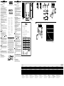
> The WSE27X-3P1830 through-beam photoelectric switch is an opto-
electronic sensor, that operates using a sender unit (WS) and receiver
unit (WE). It is used for optical, non-contact detection of objects, animals
and persons.
Starting operation
1
The devices WSE27X-3P1830 have complementary switching:
OnlyWE-3P(PNP,load→M)
Q: dark-switching, at light path interruption output HIGH.
Q: light-switching, when light path is not obstructed output HIGH.
OnlyWE-3N/-3E(NPN,load→L+)
Q: dark-switching, at light path interruption output LOW,
Q: light-switching, when light path is not obstructed output LOW.
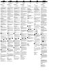
Connected desired operating mode in accordance with B .
The following apply for connection in B : brn = brown, blk = black,
wht = white, blu = blue.
Connect cable and secure tension-free.
2 Mount WS and WE opposite each other and align roughly. The devices
have to be mounted at least with two screws to suitable holders
(e. g. SICK mounting bracket). Adjust for sensing range (see technical
data and see diagram; x = sensing range, y = operating reserve).
Connect photoelectric switch to operating voltage (see type label).
Adjustment of light reception:
Set >Sensitivity< switch to max.
Determineon/opointsofsignalstrengthindicator(WE)byswivelling
photoelectric switch horizontally and vertically. With optimum light
reception, signal strength indicator (WE) lights up. If it does not light
uporifitashes,notenoughlightisbeingreceived:readjustand/
or clean WS and WE.
3 Object detection check:
Move the object into the beam; the signal strength indicator (WE)
shouldswitcho.Ifitdoesnotswitchoorcontinuestoblink,reduce
thesensitivityusingthecontrolknobuntilitswitcheso.Itshould
switch on again when the object is removed. If it does not switch
on again, adjust the sensitivity until the switching threshold is set
correctly.
Options
The WS has a test input (TE), with which proper functioning of the device
can be checked. When the light path is clear between WS and WE (the
LEDsignalstrengthindicatorislightup),activatethetestinput(TE→M).
Thisswitchesothetransmitter.Atthesametime,theLEDsignalstrength
indicatormustswitcho,andtheswitchingstateattheoutputmustchange.
Maintenance
SICK light barriers are maintenance-free.
We recommend doing the following regularly:
– clean the external lens surfaces
– check the screw connections and plug-in connections.
Nomodicationsmaybemadetodevices.
DEUTSCH
Einweg-Lichtschranke
mit sichtbarem Rotlicht
Betriebsanleitung
Sicherheitshinweise
> Kennzeichnung:
II 3G EX nA op is IIB T4 Gc X
II 3D EX tc IIIB T135 °C Dc X
–20 °C < Ta < +50 °C
> Geräte entsprechen der Schutzart für Betriebsmittel zur Verwendung in
explosionsgefährdeten Bereichen mit brennbarem nichtleitfähigem Staub.
> Vor der Inbetriebnahme die Betriebsanleitung lesen.
> Anschluss, Montage und Einstellung nur durch Fachpersonal.
> Die Strahlung des Sendelichts darf nicht durch zusätzliche optische
Bauteile fokussiert werden.
> Trennen Sie die elektrischen Anschlüsse des Geräts nur in spannungs-
freiem Zustand, denn beim Trennen von stromführenden Teilen können
Funken entstehen. Dadurch besteht im explosionsgefährdeten Bereich
Lebensgefahr.
> Gerät bei Inbetriebnahme vor Feuchte und Verunreinigung schützen.
> Kein Sicherheitsbauteil gemäß EU-Maschinenrichtlinie.
> UL: Nur zur Verwendung in Anwendungen gemäß NFPA 79.
Diese Geräte müssen mit einer für 30 V DC geeigneten 1 A-Sicherung
abgesichert werden. Von UL gelistete Adapter mit Anschlusskabeln sind
verfügbar. Enclosure type 1.
Achtung, besondere Bedingung
> Wählen Sie die Montageposition so, dass die Frontscheibe keiner
UV-Strahlung (z. B. Sonnenlicht) ausgesetzt ist.
UV-Strahlung kann die Lebensdauer und die Beständigkeit der
Gerätefrontscheibe reduzieren.
> Das Gerät ist so zu errichten, dass nicht mit einer mechanischen
Beschädigung zu rechnen ist.
> NICHT UNTER SPANNUNG TRENNEN!
> Die mitgelieferte Steckersicherung muss angebracht werden, damit
ein Trennen des Steckers ohne Werkzeug verhindert wird (wenn im
Lieferumfang enthalten).
> Bei der Befestigung ist auf eine leitende Verbindung zu achten.
Der Errichtungsort ist in den Potentialausgleich einzubinden.
> Übermäßige Zugbelastung am Kabel ist zu vermeiden.
Bestimmungsgemäße Verwendung
> Richtlinienkonformität Explosionsschutz:
Richtlinie 2014 / 34 / EU.
> Die Geräte entsprechen der Kategorie 3D / 3G und können in den
explosionsgefährdeten Bereichen „Zone 22: nichtleitende Stäube“ und
„Zone 2“ eingesetzt werden.
> Die Einweg-Lichtschranke WSE27X-3P1830 ist ein opto ele k tro nischer
Sensor, der mit einer Sende- (WS) und Empfangseinheit (WE) arbeitet.
Sie wird zum optischen, berührungslosen Erfassen von Sachen, Tieren
und Personen eingesetzt.
Inbetriebnahme
1
Die Geräte WSE27X-3P1830 haben antivalente Schaltausgänge:
NurWE-3P(PNP,Last→M).
Q: dunkelschaltend bei Lichtweg-Unterbrechung, Ausgang HIGH.
Q: hellschaltend, bei Lichtweg frei, Ausgang HIGH.
NurWE-3N/-3E(NPN,Last→L+).
Q: dunkelschaltend, bei Lichtweg-Unterbrechung, Ausgang LOW,
Q: hellschaltend, bei Lichtweg frei, Ausgang LOW.
Gewünschte Betriebsart gemäß B anschließen.
Für Anschluss in B gilt: brn = braun, blk = schwarz, wht = weiß,
blu = blau.
Leitungen nur im spannungsfreien Zustand anschließen.
2 WS und WE gegenüberliegend grob ausrichten. WS und WE müssen
jeweils mit mindestens zwei Schrauben an geeignete Halter
(z. B. SICK-Haltewinkel) angeschraubt werden. Dabei Reichweite
beachten (s. technische Daten und s. Diagramm; x = Reichweite,
y = Funktionsreserve).
WS und WE an Betriebsspannung legen (s. Typenaufdruck).
Betriebsanzeige bei WS leuchtet.
Justage Lichtempfang:
Drehknopf >Sensitivity< auf max. stellen.
Ein- / Ausschaltpunkte der Empfangsanzeige (WE) durch horizontales
und vertikales Schwenken der Lichtschranke ermitteln. Bei optimalem
Lichtempfang leuchtet die Empfangsanzeige (WE) permanent. Leuchtet
sie nicht oder blinkt sie, wird kein oder zuwenig Licht empfangen: WS
und WE neu justieren bzw. reinigen.
3 Kontrolle Objekterfassung:
Objekt in den Strahlengang bringen; die Empfangsanzeige (WE) muss
erlöschen.Leuchtetsieweiterhinoderblinktsie,dieEmpndlichkeit
am Drehknopf so lange reduzieren, bis sie erlischt. Nach Entfernen
desObjektesmusssiewiederaueuchten;istdiesnichtderFall,
Empndlichkeitsolangeverändern,bisdieSchaltschwellekorrekt
eingestellt ist.
Optionen
Der Sender verfügt über einen Testeingang (TE), mit dem die ordnungs-
gemäße Funktion der Geräte überprüft werden kann. Bei freiem Lichtweg
zwischen WS und WE (Empfangsanzeige leuchtet) den Testeingang aktivie-
ren(TE→M);dadurchwirdderSenderabgeschaltet.Gleichzeitigmussdie
Empfangsanzeige erlöschen, und der Schaltzustand am Ausgang muss sich
ändern.
Wartung
SICK-Lichtschranken sind wartungsfrei.
Wir empfehlen, in regelmäßigen Abständen
–dieoptischenGrenzächenzureinigen,
– Verschraubungen und Steckverbindungen zu überprüfen.
Veränderungen an Geräten dürfen nicht vorgenommen werden.
WSE27X-
3P1830
------------------------------------------------------- 8011740.11HQ 0219 COMAT ---------------------------------------------------
5
(16.40)
10
(32.81)
15
(49.21)
20
(65.62)
25
(82.02)
30
(98.43)
35
(114.83)
40
(131.23)
1,000
10,000
100
10
1
Distance in m (feet)
0
y operating reserve
L+
Q
M
brn
blk
wht
blu
L+
TE
NC
M
brn
blk
wht
blu
NPN
0
Q
Q
Q
Q
PNP
1
0
1
0
1
0
1
WS
WE
Morerepresentativesandagenciesatwww.sick.com∙Subjecttochange
withoutnotice∙Thespeciedproductfeaturesandtechnicaldatadonot
represent any guarantee.
WeitereNiederlassungenndenSieunterwww.sick.com∙Irrtümer
undÄnderungenvorbehalten∙AngegebeneProdukteigenschaftenund
technische Daten stellen keine Garantieerklärung dar.
Plusdereprésentationsetd’agencesàl’adressewww.sick.com∙Sujetà
modicationsanspréavis∙Lescaractéristiquesdeproduitettechniques
indiquées ne constituent pas de déclaration de garantie.
Paramaisrepresentanteseagências,consultewww.sick.com∙Alterações
poderãoserfeitassemprévioaviso∙Ascaracterísticasdoprodutoeos
dadostécnicosapresentadosnãoconstituemdeclaraçãodegarantia.
Altrirappresentantiedagenziesitrovanosuwww.sick.com∙Contenuti
soggettiamodichesenzapreavviso∙Lecaratteristichedelprodottoeidati
tecnici non rappresentano una dichiarazione di garanzia.
Másrepresentantesyagenciasenwww.sick.com∙Sujetoacambiosin
previoaviso∙Lascaracterísticasylosdatostécnicosespecicadosno
constituyenningunadeclaracióndegarantía.
欲了解更多代表机构和代理商信息,请登录 www.sick.com∙
如有更改 , 不另行通知∙对所给出的产品特性和技术参数
的正确性不予保证。
その他の営業所は www.sick.com よりご覧ください∙予告なし
に変更されることがあります∙ 記載されている製品機能およ
び技術データは保証を明示するものではありません。
EU Declaration of conformity
The undersigned, representing the following manufacturer
SICK AG
Erwin-Sick-Straße 1
79183 Waldkirch
Germany
herewith declares, that the products of the product family
W.24-2…..S.. (ATEX)
are in conformity with the provisions of the following directives (including all applicable
amendments), and that the standards and/or technical specifications referenced below have
been applied.
II 3G Ex nA op is IIB T4 Gc X
II 3D Ex tc IIIB T135 °C Dc X
-20 °C < Ta < +50 °C
Used directives and standards:
Directives
Official Journal
of the EU L96
Title or short description Issued
Directive 2014/30/EU EMC-Directive – electromagnetic compatibility 2014 – 02
Directive 2014/34/EU 2014 – 02
EN 60947 – 5 – 2 2007 – 12
EN 60079 – 0 Explosive atmospheres – part 0: Equipment
– General requirements
2012 – 08
EN 60079 – 15 2010 – 05
EN 60079 – 0 / A11 Explosive atmospheres – part 0: Equipment
– General requirements
Explosive atmospheres – part 15: Equipment
protection by type of protection „n“
2013 – 11
EN 60079 – 28 Explosive atmospheres - Part 28: Protection of
equipment and transmission systems using optical
radiation
2007 – 03
EN 60079 – 31 Explosive atmospheres - Part 31: Equipment dust
ignition protection by enclosure "t"
2009 – 12
Equipment and protective systems intended for
use in potentially explosive atmosphere
Standards
Title or short description Issued
Low voltage switchgear and controlgear – part 5-6:
Control circuit devices and switching elements
– proximity switches
16.6
(0.65)
15
(0.59)
40
(1.57)
70.4
(2.77)
31.4
(1.24)
54.5 (2.15)
92 (3.62)
112.3
(4.42)
8
(0.31)
70 (2.76)
31.5 (1.24)
76.5 (3.01) 10 (0.39)
All dimensions in mm (inch)
WSE27X-3P1830
II 3G EX nA op is IIB T4 Gc X
II 3D EX tc IIIB T135 °C Dc X
–20 °C < Ta < +50 °C
Sensing range Schaltabstand Distance de commutation Distânciadecomutação Distanza di commutazione Distancia de conmutación
开关距离 検出範囲
Расстояниесрабатывания 0 ... 25 m
Light spot diameter / distance Lichtfleckdurchmesser / Entfernung Diamètre spot / distance Diâmetro do ponto de luz / distância Diametro punto luminoso / distanza Diámetro del punto luminoso / distancia
光斑直径 / 距离 光点のスポット径 / 距離 Диаметрсветовогопятна/расстояние ~ 600 mm / 25 m
Supply voltage V
S
Versorgungsspannung U
V
Tension d'alimentation U
V
TensãodeforçaU
V
Tensione di alimentazione U
V
Tensión de alimentación U
V
供电电压 U
V
供給電圧 U
V
НапряжениепитанияU
V
10 ... 30 V DC
1)
Output current I
max.
Ausgangsstrom I
max.
Courant de sortie I
max.
CorrentedesaídaI
max.
Corrente di uscita max. I
max.
Corriente de salida I
max.
输出电流 I
max.
出力電流 I
max.
ВыходнойтокI
макс.
100 mA
Max. switching frequency Schaltfolge max. Cadence de commutation maxi Seqüênciadeligaçõesmáx. Sequenza di commutazione max. Secuencia de maniobras max.
最大开关操作顺序 最大スイッチング周波数
Частотасрабатываниямакс. 1000 / s
2)
Response time Ansprechzeit Temps de réponse Tempodereação Tempo di risposta Tiempo de reacción
最长响应时间 最大応答時間
Времяотклика ≤500µs
3)
Enclosure rating Schutzart Type de protection Tipodeproteção Tipo di protenzione Tipo de protección
防护类型 保護等級
Классзащиты IP 67
Protection class Schutzklasse Classe de protection Classedeproteção Classe di protezione Protección clase
防护等级 保護クラス
Классзащиты
4)
Circuit protection Schutzschaltungen Circuits de protection Circuitos protetores Commutazioni di protezione Circuitos de protección
保护电路 回路保護
Схемызащиты A, B, C
5)
Ambient operating temperature Betriebsumgebungstemperatur Température ambiante de fonctionnement Temperatura ambiente operacional Temperatura di lavoro Temperatura ambiente de servicio
工作环境温度 周辺温度
Диапазонрабочихтемператур –20 °C ... +50 °C
1)
Limit s
Ripple max. 0.4 V
SS
2)
With light / dark ratio 1:1
3)
Signal transit time with resistive load
4)
Reference voltage < 50 V DC
5)
A = V
S
connections reverse polarity protected
B = Output Q and Q – short-circuit protected
C = Interference pulse suppression
1)
Grenzwerte
Restwelligkeit max. 0,4 V
SS
2)
Bei Hell- / Dunkelverhältnis 1:1
3)
Signallaufzeit bei ohmscher Last
4)
Bemessungsspannung < 50 V DC
5)
A = U
V
-Anschlüsse verpolsicher
B = Ausgang Q und Q – kurzschlussgeschützt
C = Störimpulsunterdrückung
1)
Valeurs limites
Ondulation résiduelle maxi 0,4 V
SS
2)
Pour un rapport clair / sombre de 1:1
3)
Temps de propagation du signal sous charge ohmique
4)
Tension de calcul < 50 V c.c.
5)
A = Raccordements U
V
protégés contre les inversions de polarité
B = Sorties Q et Q – protégées contre les courts-circuits
C = Suppression des impulsions parasites
1)
Valores limite
Ondulaçãoresidualmáx.0.4V
SS
2)
Comrelaçãoclaro/escuro1:1
3)
Tempodetransiçãodosinalcomcargaôhmica
4)
Tensão de dimensionamento < DC 50 V
5)
A=ConexõesU
V
protegidas contra inversão de polos
B=SaídasQeQ – protegida contra curto-circuitos
C = Supressão de impulsos parasitas
1)
Valori limite
Ondulatione residua max. 0,4 V
SS
2)
Con rapporto chiaro / scuro 1:1
3)
Tempo di transito segnale con carico ohmico
4)
Tensione di taratura < DC 50 V
5)
A = U
V
-collegamenti con protez.contro inversione di poli
B = Uscita Q e Q – a prova di corto circuito
C = Soppressione impulsi di disturbo
1)
Valoreslímite
Ondulación residual max. 0,4 V
SS
2)
Con una relación claro / oscuro 1:1
3)
Tiempo de propagación de la señal con carga óhmica
4)
Tensión tolerable < DC 50 V
5)
A = Conexiones U
V
a prueba de inversión de polaridad
B = Salida Q y Q – protegida contra cortocircuito
C = Represión de impulso de interferencia
1)
极限值
最大余波 0,4 V
SS
2)
明暗比为 1:1
3)
信号传输时间(电阻负载时)
4)
测量电压 DC 50 V
5)
A = U
V
-接头防反接
B = 输出端 Q 和 Q(已采取短路保护措施)
C = 消除干扰脉冲
1)
限界値
残留リップルは最大 0,4 V
SS
2)
ライト / ダークの比率 1:1
3)
負荷のある信号経過時間
4)
定格電圧 DC 50 V
5)
A = U
V
接口(已采取反极性保护措施)
B = 出力回路 Q および Q 短絡保護
C = 抑制干扰脉冲
1)
Предельныезначения
остаточнаяволнистостьмакс.0,4V
SS
2)
Соотношениесветлыхитемныхучастковизображения1:1
3)
Продолжительностьсигналаприомическойнагрузке
4)
РасчетноенапряжениеDC50V
5)
A = U
V
-подключениясзащитойотперепутыванияполюсов
B=ВыходQиQсзащитойоткороткогозамыкания
C=Подавлениеимпульсныхпомех
A
B
SICK AG, Erwin-Sick-Strasse 1, D-79183 Waldkirch
BZ int48
Please find detailed addresses and further locations in all major industrial
nations at www.sick.com
Australia
Phone +61 (3) 9457 0600
Austria
Phone +43 (0) 2236 62288-0
Belgium/Luxembourg
Phone +32 (0) 2 466 55 66
Brazil
Phone +55 11 3215-4900
Canada
Phone +1 905.771.1444
Czech Republic
Phone +420 2 57 91 18 50
Chile
Phone +56 (2) 2274 7430
China
Phone +86 20 2882 3600
Denmark
Phone +45 45 82 64 00
Finland
Phone +358-9-25 15 800
France
Phone +33 1 64 62 35 00
Germany
Phone +49 (0) 2 11 53 01
Hong Kong
Phone +852 2153 6300
Hungary
Phone +36 1 371 2680
India
Phone +91-22-6119 8900
Israel
Phone +972-4-6881000
Italy
Phone +39 02 27 43 41
Japan
Phone +81 3 5309 2112
Malaysia
Phone +603-8080 7425
Mexico
Phone +52 (472) 748 9451
Netherlands
Phone +31 (0) 30 229 25 44
New Zealand
Phone +64 9 415 0459
Norway
Phone +47 67 81 50 00
Poland
Phone +48 22 539 41 00
Romania
Phone +40 356-17 11 20
Russia
Phone +7 495 283 09 90
Singapore
Phone +65 6744 3732
Slovakia
Phone +421 482 901 201
Slovenia
Phone +386 591 78849
South Africa
Phone +27 (0)11 472 3733
South Korea
Phone +82 2 786 6321
Spain
Phone +34 93 480 31 00
Sweden
Phone +46 10 110 10 00
Switzerland
Phone +41 41 619 29 39
Taiwan
Phone +886-2-2375-6288
Thailand
Phone +66 2 645 0009
Turkey
Phone +90 (216) 528 50 00
United Arab Emirates
Phone +971 (0) 4 88 65 878
United Kingdom
Phone +44 (0)17278 31121
USA
Phone +1 800.325.7425
Vietnam
Phone +65 6744 3732
2006/42/EC
NO
SAFETY
Seite wird geladen ...
-
 1
1
-
 2
2


in anderen Sprachen
- English: SICK WSE27X-3P1830 Operating instructions
- français: SICK WSE27X-3P1830 Mode d'emploi
- español: SICK WSE27X-3P1830 Instrucciones de operación
- italiano: SICK WSE27X-3P1830 Istruzioni per l'uso
- русский: SICK WSE27X-3P1830 Инструкция по эксплуатации
- português: SICK WSE27X-3P1830 Instruções de operação
- 日本語: SICK WSE27X-3P1830 取扱説明書
Verwandte Artikel
-
SICK WL27X-3P1831 /WL27X3-P3431 Bedienungsanleitung
-
-
-
-
-
-
-
-
-