Pepperl+Fuchs OCS2000-M1K-N2 Bedienungsanleitung
- Typ
- Bedienungsanleitung

alle Maße in mm
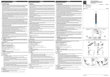
Dimensions
Abmessungen
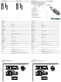
Technische Daten
Technical data
Elektrischer Anschluss
Electrical connection
Adressen/Addresses
Sicherheitshinweise:
• Vor der Inbetriebnahme Betriebsanleitung lesen
• Anschluss, Montage und Einstellung nur durch Fachpersonal
• Kein Sicherheitsbauteil gemäß EU-Maschinenrichtlinie
Security Instructions:
• Read the operating instructions before attempting commissioning
• Installation, connection and adjustments should only be undertaken by specialist personnel
• Not a safety component in accordance with the EU Machinery Directive
all dimensions in mm
www.pepperl-fuchs.com
Pepperl+Fuchs GmbH
68301 Mannheim · Germany
Tel. +49 621 776-4411
Fax +49 621 776-27-4411
Worldwide Headquarters
Pepperl+Fuchs GmbH · Mannheim · Germany
USA Headquarters
Pepperl+Fuchs Inc. · Twinsburg · USA
E-mail: fa-info@us.pepperl-fuchs.com
Asia Pacific Headquarters
Pepperl+Fuchs Pte Ltd · Singapore
Company Registration No. 199003130E
optische Achse
Empfänger optische Achse
Sender
Klemmraum
Klemmraum
15
4,3 x 5,3
30
30
52
102
20/22
59
30
21
15
9
104
LED
M16
3
1
4
2
Reflexionslichtschranke NAMUR
Retroreflective sensor, NAMUR
OCS2000-M1K-N2
Allgemeine Daten
Betriebsreichweite 0 ... 2 m
Reflektorabstand 100 ... 2000 mm
Grenzreichweite 2 m
Referenzobjekt Retroreflektor C110-2
Lichtsender LED , 660 nm
Lichtart rot, Wechsellicht
Polarisationsfilter ja
Fremdlichtgrenze
10000 Lux Sonnenlicht
7500 Lux Halogenlicht
Kenndaten funktionale Sicherheit
MTTFd 1319 a
Gebrauchsdauer (TM) 20 a
Diagnosedeckungsgrad (DC) 0 %
Anzeigen/Bedienelemente
Funktionsanzeige LED gelb: Schaltzustand
Elektrische Daten
Betriebsspannung UB6 ... 20 V DC (Ri ca. 0
)
Welligkeit 5 %
Bereitschaftsverzug tv20 ms
Ausgang
Schaltungsart hell-/dunkelschaltend verdrahtungsprogrammierbar
Signalausgang 1 NAMUR-Ausgang, Schließer/Öffner verdrahtungsprogrammierbar
Schaltspannung 8 V DC (Ri ca. 1 k
)
Schaltfrequenz f
100 Hz
Stromaufnahme
Referenzobjekt erkannt Anschluss 1, 2:
2,2 mA
Anschluss 1, 4:
1 mA
Referenzobjekt nicht erkannt Anschluss 1, 2:
1 mA
Anschluss 1, 4:
2,2 mA
Ansprechzeit 5 ms
Richtlinienkonformität
Elektromagnetische Verträglichkeit
Richtlinie 2014/30/EU EN 60947-5-2:2007+A1:2012
Umgebungsbedingungen
Umgebungstemperatur -25 ... 70 °C (-13 ... 158 °F)
Lagertemperatur -40 ... 80 °C (-40 ... 176 °F)
Mechanische Daten
Schutzart IP67 nach EN 60529, schutzisoliert
Anschluss Klemmraum M16, Aderquerschnitt
2,5 mm2
Material
Gehäuse PBT
Lichtaustritt kratzfeste Mineralglasscheibe
Masse 100 g
Normen- und Richtlinienkonformität
Normenkonformität
Normen EN 60947-5-6:2000
Zulassungen und Zertifikate
FM-Zulassung
Zugelassen für IS / I,II,III / 1 / ABCDEFG / T5 - 116-0110; Entity
NI / I / 2 / ABCD / T6
Entity Parameters:
VMax = 12.6 V, IMax = 20 mA, Ci = 1.11 µF, Li = 0 mH (Groups A, B, C, D, E, F, G).
VMax = 15.5 V, IMax = 52 mA, Ci = 1.11 µF, Li = 0 mH (Groups C, D, E, F, G).
CSA-Zulassung
Zugelassen für Class I, Division 2, Groups A, B, C and D
Rated 20V (max), 50mA.
These sensors are suitable for installation in (or through the wall of) a suitable enclosure with provision for connection
of rigid metal conduit, as acceptable to the local inspection authority having jurisdiction.
CCC-Zulassung Produkte, deren max. Betriebsspannung
36 V ist, sind nicht zulassungspflichtig und daher nicht mit einer CCC-
Kennzeichnung versehen.
Optical axis
emitter
Optical axis
receiver
Terminal compartment
Terminal compartment
15
4.3 x 5.3
30
30
52
102
20/22
59
30
21
15
9
104
LED
M16
3
1
4
2
07/21/2016
Date:
Option:
3
1
2
4
+UB
+UB
0 V
0 V
N2
General specifications
Effective detection range 0 ... 2 m
Reflector distance 100 ... 2000 mm
Threshold detection range 2 m
Reference target Retro-reflector C110-2
Light source LED , 660 nm
Light type modulated visible red light
Polarization filter yes
Ambient light limit
10000 Lux sun light
7500 Lux halogen light
Functional safety related parameters
MTTFd 1319 a
Mission Time (TM) 20 a
Diagnostic Coverage (DC) 0 %
Indicators/operating means
Function indicator LED yellow: switching state
Electrical specifications
Operating voltage UB6 ... 20 V DC (Ri approx. 0 Ohm)
Ripple 5 %
Time delay before availability tv20 ms
Output
Switching type light/dark on, programmable
Signal output 1 NAMUR output NC/NO programmable
Switching voltage 8 V DC (Ri approx. 1 k
)
Switching frequency f
100 Hz
Current consumption
Reference target detected connection 1, 2:
2.2 mA
connection 1, 4:
1 mA
Reference target not detected connection 1, 2:
1 mA
connection 1, 4:
2.2 mA
Response time 5 ms
Directive conformity
Electromagnetic compatibility
Directive 2014/30/EU EN 60947-5-2:2007+A1:2012
Ambient conditions
Ambient temperature -25 ... 70 °C (-13 ... 158 °F)
Storage temperature -40 ... 80 °C (-40 ... 176 °F)
Mechanical specifications
Degree of protection IP67 according to EN 60529, Class II insulation
Connection M16 terminal compartment, core cross-section
2.5 mm2
Material
Housing PBT
Optical face Scratch resistant mineral glass lens
Mass 100 g
Compliance with standards and directives
Standard conformity
Standards EN 60947-5-6:2000
Approvals and certificates
FM approval
Approved for IS / I,II,III / 1 / ABCDEFG / T5 - 116-0110; Entity
NI / I / 2 / ABCD / T6
Entity Parameters:
VMax = 12.6 V, IMax = 20 mA, Ci = 1.11 µF, Li = 0 mH (Groups A, B, C, D, E, F, G).
VMax = 15.5 V, IMax = 52 mA, Ci = 1.11 µF, Li = 0 mH (Groups C, D, E, F, G).
CSA approval
Approved for Class I, Division 2, Groups A, B, C and D
Rated 20V (max), 50mA.
These sensors are suitable for installation in (or through the wall of) a suitable enclosure with provision for connection
of rigid metal conduit, as acceptable to the local inspection authority having jurisdiction.
CCC approval CCC approval / marking not required for products rated
36 V
= dunkelschaltend,
= hellschaltend
= dark on,
= light on
Option:
3
1
2
4
+UB
+UB
0 V
0 V
N2
DIN A3 -> DIN A7
Part. 106529 45-0263K
Doc. No.:

ATEX
Normen- und Richtlinienkonformität
Normenkonformität
Normen EN 60947-5-6:2000
Zulassungen und Zertifikate
FM-Zulassung
Zugelassen für IS / I,II,III / 1 / ABCDEFG / T5 - 116-0110; Entity
NI / I / 2 / ABCD / T6
Entity Parameters:
VMax = 12.6 V, IMax = 20 mA, Ci = 1.11 µF, Li = 0 mH (Groups A, B, C, D, E, F, G).
VMax = 15.5 V, IMax = 52 mA, Ci = 1.11 µF, Li = 0 mH (Groups C, D, E, F, G).
CSA-Zulassung
Zugelassen für Class I, Division 2, Groups A, B, C and D
Rated 20V (max), 50mA.
These sensors are suitable for installation in (or through the wall of) a suitable enclosure with provision for connection of rigid
metal conduit, as acceptable to the local inspection authority having jurisdiction.
CCC-Zulassung Produkte, deren max. Betriebsspannung
36 V ist, sind nicht zulassungspflichtig und daher nicht mit einer CCC-Kennzeich-
nung versehen.
ATEX G
EG-Baumusterprüfbescheinigung PTB 01 ATEX 2203 X
Antragsteller Pepperl+Fuchs GmbH, Lilienthalstraße 200, 68307 Mannheim, Germany
CE-Kennzeichnung CE0102
ATEX-Kennzeichnung Zone 1:
¬
II 2G Ex ia op is IIC T6...T1 Gb
Richtlinienkonformität 2014/34/EU
Normen EN 60079-0:2012+A11:2013
EN 60079-11:2012
EN 60079-28:2007
Wirksame innere Kapazität Ci
75 nF
Wirksame innere Induktivität Li vernachlässigbar klein
Allgemeines Das Betriebsmittel ist entsprechend den Angaben im Datenblatt und dieser Betriebsanleitung zu betreiben. Insbesondere ist
die maximale Bemessungsspannung und der Temperaturbereich einzuhalten. Die besonderen Bedingungen sind einzuhalten!
Die EG-Baumusterprüfbescheinigung ist zu beachten.
Umgebungstemperatur Die Temperaturbereiche, abhängig von der Temperaturklasse, sind der EG-Baumusterprüfbescheinigung zu entnehmen.
Installation, Inbetriebnahme Das zugehörige Betriebsmittel muss passend zu den Einsatzbedingungen mindestens die Anforderungen der Schutzart ia und
der Gruppen II oder III erfüllen. Wegen möglicher Zündgefahren, die aufgrund von Fehlern und/oder transienten Strömen im
Potenzialausgleichsystem entstehen können, ist eine galvanische Trennung im Versorgungs- und Signalstromkreis zu bevor-
zugen. Zugehörige Betriebsmittel ohne galvanische Trennung dürfen nur eingesetzt werden, wenn die entsprechenden Anfor-
derungen nach IEC 60079-14 eingehalten werden. Die Eigensicherheit ist nur in Zusammenschaltung mit einem entsprechend
zugehörigen Betriebsmittel und gemäß dem Nachweis der Eigensicherheit gewährleistet.
Instandhaltung, Wartung An Betriebsmitteln, welche in explosionsgefährdeten Bereichen betrieben werden, darf keine Veränderung vorgenommen wer-
den. Reparaturen an diesen Betriebsmitteln sind nicht möglich.
Besondere Bedingungen
Schutz vor mechanischen Gefahren Beim Einsatz im Temperaturbereich unterhalb von -20 °C ist der Sensor durch Einbau in ein zusätzliches Gehäuse vor Schla-
geinwirkung zu schützen.
Erforderliche Schutzart bei Errichtung der Anschlussteile IP20 gemäß IEC 60529:2001
Sonstige Bedingungen Der Zusammenhang zwischen dem Typ des angeschlossenen Stromkreises, der höchstzulässigen Umgebungstemperatur
und der Temperaturklasse sowie den wirksamen inneren Reaktanzen ist der zugeordneten EG-Baumusterprüfbescheinigung
zu entnehmen.
ATEX D
EG-Baumusterprüfbescheinigung ZELM 03 ATEX 0196 X
Antragsteller Pepperl+Fuchs GmbH, Lilienthalstraße 200, 68307 Mannheim, Germany
CE-Kennzeichnung CE0102
ATEX-Kennzeichnung Zone 20/21:
¬
II 1D Ex ia IIIC T 135°C Da
Richtlinienkonformität 2014/34/EU
Normen EN 60079-0:2012+A11:2013
EN 60079-11:2012
EN 60079-28:2007
Wirksame innere Kapazität Ci
1200 nF
Wirksame innere Induktivität Li vernachlässigbar klein
Allgemeines Das Betriebsmittel ist entsprechend den Angaben im Datenblatt und dieser Betriebsanleitung zu betreiben. Insbesondere ist
die maximale Bemessungsspannung und der Temperaturbereich einzuhalten. Die besonderen Bedingungen sind einzuhalten!
Die EG-Baumusterprüfbescheinigung ist zu beachten.
Umgebungstemperatur -25 ... 70 °C (-13 ... 158 °F)
Installation, Inbetriebnahme Das zugehörige Betriebsmittel muss passend zu den Einsatzbedingungen mindestens die Anforderungen der Schutzart ia und
der Gruppen II oder III erfüllen. Wegen möglicher Zündgefahren, die aufgrund von Fehlern und/oder transienten Strömen im
Potenzialausgleichsystem entstehen können, ist eine galvanische Trennung im Versorgungs- und Signalstromkreis zu bevor-
zugen. Zugehörige Betriebsmittel ohne galvanische Trennung dürfen nur eingesetzt werden, wenn die entsprechenden Anfor-
derungen nach IEC 60079-14 eingehalten werden. Die Dichtheit von zonentrennenden Maßnahmen beim Einbau in die
Trennwand zwischen verschiedenen Zonen ist nicht Gegenstand dieser Bescheinigung und ist bei der Errichtung durch geeig-
nete Maßnahmen sicher zu stellen.
Instandhaltung, Wartung An Betriebsmitteln, welche in explosionsgefährdeten Bereichen betrieben werden, darf keine Veränderung vorgenommen wer-
den. Reparaturen an diesen Betriebsmitteln sind nicht möglich.
Besondere Bedingungen
Schutz vor gefährlicher elektrostatischer Aufladung Das Gerät soll in einer Weise installiert werden, dass Gleitstielbüschelentladungen vermieden werden. Wenn das Gerät ent-
sprechend den Anweisungen des Herstellers installiert wird, dann wird aufgrund der Beschaffenheit des Geräts keine gefährli-
che elektrostatische Aufladung erwartet.
Schutz vor mechanischen Gefahren Beim Einsatz im Temperaturbereich unterhalb von -20 °C ist der Sensor durch Einbau in ein zusätzliches Gehäuse vor Schla-
geinwirkung zu schützen.
Erforderliche Schutzart bei Errichtung der Anschlussteile IP20 gemäß IEC 60529:2001
Sonstige Bedingungen Der Zusammenhang zwischen dem Typ des angeschlossenen Stromkreises, der höchstzulässigen Umgebungstemperatur
und der Oberflächentemperatur ist der zugeordneten EG-Baumusterprüfbescheinigung zu entnehmen. Bei Einsatzfällen mit zu
erwartender hoher Aufladung (z. B. elektrostatische Lackierung, Folienherstellung, Staubförderung, maschinelle Reibvor-
gänge) ist zur Vermeidung von Gleitstielbüschelentladungen die dieser Aufladung ausgesetzte Kunststoff-Gehäuseoberfläche
durch Einbaumaßnahmen auf etwa 15 cm2 zu begrenzen. Die Dichtheit im Sinne von Zonen trennenden Maßnahmen bei Ein-
bau in die Trennwand zwischen verschiedenen Zonen ist bei der Errichtung durch geeignete Maßnahmen sicher zu stellen.
IECEx G
Nummer des Zertifikats IECEx PTB 12.0060 X
Antragsteller Pepperl+Fuchs GmbH, Lilienthalstraße 200, 68307 Mannheim, Germany
IECEx-Kennzeichnung Zone 1:
¬
II 2G Ex ia op is IIC T6...T1 Gb
Normen IEC 60079-0:2011 IEC 60079-11:2011 IEC 60079-28:2006
Wirksame innere Kapazität Ci
75 nF
Wirksame innere Induktivität Li vernachlässigbar klein
Allgemeines Das Betriebsmittel ist entsprechend den Angaben im Datenblatt und dieser Betriebsanleitung zu betreiben. Insbesondere ist
die maximale Bemessungsspannung und der Temperaturbereich einzuhalten. Die besonderen Bedingungen sind einzuhalten!
Das IECEx-Zertifikat ist zu beachten.
Umgebungstemperatur Die Temperaturbereiche, abhängig von der Temperaturklasse, sind der EG-Baumusterprüfbescheinigung zu entnehmen.
Installation, Inbetriebnahme Das zugehörige Betriebsmittel muss passend zu den Einsatzbedingungen mindestens die Anforderungen der Schutzart ia und
der Gruppen II oder III erfüllen. Wegen möglicher Zündgefahren, die aufgrund von Fehlern und/oder transienten Strömen im
Potenzialausgleichsystem entstehen können, ist eine galvanische Trennung im Versorgungs- und Signalstromkreis zu bevor-
zugen. Zugehörige Betriebsmittel ohne galvanische Trennung dürfen nur eingesetzt werden, wenn die entsprechenden Anfor-
derungen nach IEC 60079-14 eingehalten werden. Die Eigensicherheit ist nur in Zusammenschaltung mit einem entsprechend
zugehörigen Betriebsmittel und gemäß dem Nachweis der Eigensicherheit gewährleistet.
Instandhaltung, Wartung An Betriebsmitteln, welche in explosionsgefährdeten Bereichen betrieben werden, darf keine Veränderung vorgenommen wer-
den. Reparaturen an diesen Betriebsmitteln sind nicht möglich.
Besondere Bedingungen
Schutz vor mechanischen Gefahren Beim Einsatz im Temperaturbereich unterhalb von -20 °C ist der Sensor durch Einbau in ein zusätzliches Gehäuse vor Schla-
geinwirkung zu schützen.
Erforderliche Schutzart bei Errichtung der Anschlussteile IP20 gemäß IEC 60529:2001
Sonstige Bedingungen Der Zusammenhang zwischen dem Typ des angeschlossenen Stromkreises, der höchstzulässigen Umgebungstemperatur
und der Temperaturklasse sowie den wirksamen inneren Reaktanzen ist der zugeordneten EG-Baumusterprüfbescheinigung
zu entnehmen.
IECEx D
Nummer des Zertifikats IECEx ZLM 12.0005X
Antragsteller Pepperl+Fuchs GmbH, Lilienthalstraße 200, 68307 Mannheim, Germany
IECEx-Kennzeichnung Ex ia IIIC T135°C Da
Normen IEC 60079-0:2011 IEC 60079-11:2011
Wirksame innere Kapazität Ci
1200 nF
Wirksame innere Induktivität Li vernachlässigbar klein
Allgemeines Das Betriebsmittel ist entsprechend den Angaben im Datenblatt und dieser Betriebsanleitung zu betreiben. Insbesondere ist
die maximale Bemessungsspannung und der Temperaturbereich einzuhalten. Die besonderen Bedingungen sind einzuhalten!
Das IECEx-Zertifikat ist zu beachten.
Umgebungstemperatur -25 ... 70 °C (-13 ... 158 °F)
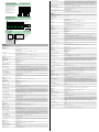
X [m]
Y [mm] OCS2000-M1K-N2
x
y
10
0
20
30
40
50
60
70
80
90
0 0,5 1 1,5 2 2,5 3 3,5
H85
C110-2
H60
H160
F2000
Charakteristische Ansprechkurve
Courbe de response caractéristique
Curve di risposta caratteristica
Characteristic response curve
Curva de respuesta característica
Möglicher Abstand (Versatz) zwischen
optischer Achse und Referenzobjekt.
Permissible distance (offset) between
optical axis and reference target.
Ecart possible entre l'axe optique et la
cible de référence.
Desplazamiento entre el eje óptico y
objeto de referencia.
Distanza possibile (sfalsato) tra l'asse
ottico e l'ogetto di riferimento.
X [m]
MLV11-54-Ex/40b/112
x
H85
C110-2
H60
H160
F2000
0
1
2
3
4
5
6
7
8
9
10
012345
Relative Empfangslichtstärke
Intensité relative de la lumière reçue
Intensità relativa luce in ricezione
Relative received light strength
Potencia relativa de recepción lumínica
Funktionsreserve,
Stability control, Réserve de fonctionnement,
Reserva de función, Funzione riserva
Reflektor/Reflector
Réflecteur/Reflector
Riflettore
NAMUR-Sensoren
Détecteurs NAMUR
Sensori NAMUR
NAMUR Sensors
Sensores NAMUR
NAMUR - Sensor
NAMUR Sensor
Détecteur NAMUR
Sensor NAMUR
Sensore NAMUR
Trennschaltgerät
Transformer Isolated Amplifier
Commutateur séparateur
Conmutador Separador
Apparecchio di comando separazione
Ex-Bereich
Hazardous area
Zone classée
Área peligrosa
Area esplosiva
Nicht Ex-Bereich
Safe area
Zone non classée
Área segura
Area non esplosiva
Stromversorgung
Power supply
Alimentation
Fuente de alimentación
Alimentazione
(Beispiel, Example: KFD2-SR2-Ex1.W)
Installation, Inbetriebnahme Das zugehörige Betriebsmittel muss passend zu den Einsatzbedingungen mindestens die Anforderungen der Schutzart ia und
der Gruppen II oder III erfüllen. Wegen möglicher Zündgefahren, die aufgrund von Fehlern und/oder transienten Strömen im
Potenzialausgleichsystem entstehen können, ist eine galvanische Trennung im Versorgungs- und Signalstromkreis zu bevor-
zugen. Zugehörige Betriebsmittel ohne galvanische Trennung dürfen nur eingesetzt werden, wenn die entsprechenden Anfor-
derungen nach IEC 60079-14 eingehalten werden. Die Dichtheit von zonentrennenden Maßnahmen beim Einbau in die
Trennwand zwischen verschiedenen Zonen ist nicht Gegenstand dieser Bescheinigung und ist bei der Errichtung durch geeig-
nete Maßnahmen sicher zu stellen.
Instandhaltung, Wartung An Betriebsmitteln, welche in explosionsgefährdeten Bereichen betrieben werden, darf keine Veränderung vorgenommen wer-
den. Reparaturen an diesen Betriebsmitteln sind nicht möglich.
Besondere Bedingungen
Schutz vor gefährlicher elektrostatischer Aufladung Das Gerät soll in einer Weise installiert werden, dass Gleitstielbüschelentladungen vermieden werden. Wenn das Gerät ent-
sprechend den Anweisungen des Herstellers installiert wird, dann wird aufgrund der Beschaffenheit des Geräts keine gefährli-
che elektrostatische Aufladung erwartet.
Schutz vor mechanischen Gefahren Beim Einsatz im Temperaturbereich unterhalb von -20 °C ist der Sensor durch Einbau in ein zusätzliches Gehäuse vor Schla-
geinwirkung zu schützen.
Erforderliche Schutzart bei Errichtung der Anschlussteile IP20 gemäß IEC 60529:2001
Sonstige Bedingungen Die Dichtheit im Sinne von Zonen trennenden Maßnahmen bei Einbau in die Trennwand zwischen verschiedenen Zonen ist
bei der Errichtung durch geeignete Maßnahmen sicher zu stellen.
ATEX
Compliance with standards and directives
Standard conformity
Standards EN 60947-5-6:2000
Approvals and certificates
FM approval
Approved for IS / I,II,III / 1 / ABCDEFG / T5 - 116-0110; Entity
NI / I / 2 / ABCD / T6
Entity Parameters:
VMax = 12.6 V, IMax = 20 mA, Ci = 1.11 µF, Li = 0 mH (Groups A, B, C, D, E, F, G).
VMax = 15.5 V, IMax = 52 mA, Ci = 1.11 µF, Li = 0 mH (Groups C, D, E, F, G).
CSA approval
Approved for Class I, Division 2, Groups A, B, C and D
Rated 20V (max), 50mA.
These sensors are suitable for installation in (or through the wall of) a suitable enclosure with provision for connection of rigid
metal conduit, as acceptable to the local inspection authority having jurisdiction.
CCC approval CCC approval / marking not required for products rated
36 V
ATEX G
EC-Type Examination Certificate PTB 01 ATEX 2203 X
Applicant Pepperl+Fuchs GmbH, Lilienthalstrasse 200, 68307 Mannheim, Germany
CE marking CE0102
ATEX marking Zone 1:
¬
II 2G Ex ia op is IIC T6...T1 Gb
Directive conformity 2014/34/EU
Standards EN 60079-0:2012+A11:2013
EN 60079-11:2012
EN 60079-28:2007
Effective internal capacitance Ci
75 nF
Effective internal inductance Li negligibly small
General The apparatus must be operated in accordance with the data provided in the data sheet and this operating instruction. In parti-
cular, the maximum rated voltage and the temperature range must be adhered to. The special conditions must be adhered to!
The EC-Type Examination Certificate has to be observed.
Ambient temperature The temperature ranges, according to temperature class, are given in the EC-Type Examination Certificate.
Installation, commissioning The associated apparatus must, as a minimum, fulfill the requirements for degree of protection ia and for Groups II or III, as
appropriate for the operating conditions. Due to the possible risk of ignition that can occur as a result of faults and/or transient
currents in the equipotential bonding system, galvanic isolation in the supply and signal current circuit is preferred. Associated
apparatus without galvanic isolation may only be used if the appropriate requirements as set out in IEC 60079-14 are met. The
intrinsic safety is only assured in connection with an appropriate related apparatus and according to the proof of intrinsic safety.
Maintenance No modifications must be undertaken on apparatus, which is operated in hazardous areas. Repairs to such apparatus are not
permissible.
Special conditions
Protection from mechanical danger When used in the temperature range below -20 °C the sensor should be protected from knocks by the provision of an additio-
nal housing.
Degree of protection required when installing connecting
components
IP20 according to IEC 60529:2001
Other conditions Refer to the relevant EC type examination certificate to see the relationship between the connected circuit type, the maximum
permitted ambient temperature and the temperature class as well as effective inner reactances.
ATEX D
EC-Type Examination Certificate ZELM 03 ATEX 0196 X
Applicant Pepperl+Fuchs GmbH, Lilienthalstrasse 200, 68307 Mannheim, Germany
CE marking CE0102
ATEX marking Zone 20/21:
¬
II 1D Ex ia IIIC T 135°C Da
Directive conformity 2014/34/EU
Standards EN 60079-0:2012+A11:2013
EN 60079-11:2012
EN 60079-28:2007
Effective internal capacitance Ci
1200 nF
Effective internal inductance Li negligibly small
General The apparatus must be operated in accordance with the data provided in the data sheet and this operating instruction. In parti-
cular, the maximum rated voltage and the temperature range must be adhered to. The special conditions must be adhered to!
The EC-Type Examination Certificate has to be observed.
Ambient temperature -25 ... 70 °C (-13 ... 158 °F)
Installation, commissioning The associated apparatus must, as a minimum, fulfill the requirements for degree of protection ia and for Groups II or III, as
appropriate for the operating conditions. Due to the possible risk of ignition that can occur as a result of faults and/or transient
currents in the equipotential bonding system, galvanic isolation in the supply and signal current circuit is preferred. Associated
apparatus without galvanic isolation may only be used if the appropriate requirements as set out in IEC 60079-14 are met. This
certificate does not guarantee that the components installed in the partition isolate the zones completely from one another.
Appropriate measures must be taken when the partition is set up to ensure the zones are completely isolated.
Maintenance No modifications must be undertaken on apparatus, which is operated in hazardous areas. Repairs to such apparatus are not
permissible.
Special conditions
Protection against dangerous electrostatic charging The device must be installed such that electrostatic discharges can be avoided. If the device is installed in accordance with the
instructions provided by the manufacturer, no dangerous electrostatic charge is to be expected given the properties of the
device.
Protection from mechanical danger When used in the temperature range below -20 °C the sensor should be protected from knocks by the provision of an additio-
nal housing.
Degree of protection required when installing connecting
components
IP20 according to IEC 60529:2001
Other conditions Refer to the relevant EC type examination certificate to see the relationship between the connected circuit type, the maximum
permitted ambient temperature and the surface temperature class. In applications where high levels of charge are expected
(e.g. electrostatic paint, foil manufacture, dust extraction, mechanical friction), structural measures must be taken to limit the
surface area of the plastic housing exposed to this charge to approximately 15 cm2 in order to avoid propagating brush
discharge. When setting up a partition between different zones, appropriate measures must be taken to ensure that the com-
ponents installed in the partition isolate the zones completely from one another.
IECEx G
Certificate number IECEx PTB 12.0060 X
Applicant Pepperl+Fuchs GmbH, Lilienthalstrasse 200, 68307 Mannheim, Germany
IECEx marking Zone 1:
¬
II 2G Ex ia op is IIC T6...T1 Gb
Standards IEC 60079-0:2011 IEC 60079-11:2011 IEC 60079-28:2006
Effective internal capacitance Ci
75 nF
Effective internal inductance Li negligibly small
General The apparatus must be operated in accordance with the data provided in the data sheet and this operating instruction. In parti-
cular, the maximum rated voltage and the temperature range must be adhered to. The special conditions must be adhered to!
The IECEx certificate must be observed.
Ambient temperature The temperature ranges, according to temperature class, are given in the EC-Type Examination Certificate.
Installation, commissioning The associated apparatus must, as a minimum, fulfill the requirements for degree of protection ia and for Groups II or III, as
appropriate for the operating conditions. Due to the possible risk of ignition that can occur as a result of faults and/or transient
currents in the equipotential bonding system, galvanic isolation in the supply and signal current circuit is preferred. Associated
apparatus without galvanic isolation may only be used if the appropriate requirements as set out in IEC 60079-14 are met. The
intrinsic safety is only assured in connection with an appropriate related apparatus and according to the proof of intrinsic safety.
Maintenance No modifications must be undertaken on apparatus, which is operated in hazardous areas. Repairs to such apparatus are not
permissible.
Special conditions
Protection from mechanical danger When used in the temperature range below -20 °C the sensor should be protected from knocks by the provision of an additio-
nal housing.
Degree of protection required when installing connecting
components
IP20 according to IEC 60529:2001
Other conditions Refer to the relevant EC type examination certificate to see the relationship between the connected circuit type, the maximum
permitted ambient temperature and the temperature class as well as effective inner reactances.
IECEx D
Certificate number IECEx ZLM 12.0005X
Applicant Pepperl+Fuchs GmbH, Lilienthalstrasse 200, 68307 Mannheim, Germany
IECEx marking Ex ia IIIC T135°C Da
Standards IEC 60079-0:2011 IEC 60079-11:2011
Effective internal capacitance Ci
1200 nF
Effective internal inductance Li negligibly small
General The apparatus must be operated in accordance with the data provided in the data sheet and this operating instruction. In parti-
cular, the maximum rated voltage and the temperature range must be adhered to. The special conditions must be adhered to!
The IECEx certificate must be observed.
Ambient temperature -25 ... 70 °C (-13 ... 158 °F)
Installation, commissioning The associated apparatus must, as a minimum, fulfill the requirements for degree of protection ia and for Groups II or III, as
appropriate for the operating conditions. Due to the possible risk of ignition that can occur as a result of faults and/or transient
currents in the equipotential bonding system, galvanic isolation in the supply and signal current circuit is preferred. Associated
apparatus without galvanic isolation may only be used if the appropriate requirements as set out in IEC 60079-14 are met. This
certificate does not guarantee that the components installed in the partition isolate the zones completely from one another.
Appropriate measures must be taken when the partition is set up to ensure the zones are completely isolated.
Maintenance No modifications must be undertaken on apparatus, which is operated in hazardous areas. Repairs to such apparatus are not
permissible.
Special conditions
Protection against dangerous electrostatic charging The device must be installed such that electrostatic discharges can be avoided. If the device is installed in accordance with the
instructions provided by the manufacturer, no dangerous electrostatic charge is to be expected given the properties of the
device.
Protection from mechanical danger When used in the temperature range below -20 °C the sensor should be protected from knocks by the provision of an additio-
nal housing.
Degree of protection required when installing connecting
components
IP20 according to IEC 60529:2001
Other conditions When setting up a partition between different zones, appropriate measures must be taken to ensure that the components
installed in the partition isolate the zones completely from one another.
-
 1
1
-
 2
2