WIKA DIH50 tag:model:DIH52 Bedienungsanleitung
- Typ
- Bedienungsanleitung

DE
EN
Operating instructions
Betriebsanleitung
Field display models DIH5x-F, DIH5x-I, DIH5x-S
Field indicator for current loops with HART
®
communication
Models DIH50, DIH52
Feldanzeige für Stromschleifen mit HART
®
-Kommunikation
Typen DIH50, DIH52

DE
EN
2
WIKA operating instructions models DIH50, DIH52
14008548.05 12/2016 EN/DE
© 05/2011 WIKA Alexander Wiegand SE & Co. KG
All rights reserved. / Alle Rechte vorbehalten.
WIKA
®
is a registered trademark in various countries.
WIKA
®
ist eine geschützte Marke in verschiedenen Ländern.
Prior to starting any work, read the operating instructions!
Keep for later use!
Vor Beginn aller Arbeiten Betriebsanleitung lesen!
Zum späteren Gebrauch aufbewahren!
Operating instructions models DIH50, DIH52
Page 3 - 32
Betriebsanleitung Typen DIH50, DIH52
Seite 33 - 59
Further languages can be found at www.wika.com.

WIKA operating instructions models DIH50, DIH52
3
EN
14008548.05 12/2016 EN/DE
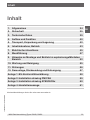
Contents
Contents
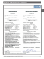
Declarations of conformity can be found online at www.wika.com.
1. General information 4
2. Safety 5
3. Specifications 9
4. Design and function 10
5. Transport, packaging and storage 12
6. Commissioning, operation 13
7. Electrical connection 15
8. Menu guidance 17
9. Information on mounting and operation in hazardous areas 22
10. Maintenance and cleaning 25
11. Faults 26
12. Dismounting, return and disposal 27
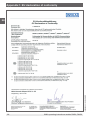
Appendix 1: EU declaration of conformity 28
Appendix 2: FM/CSA installation drawing 29
Appendix 3: ATEX/IECEx installation drawing 30
Appendix 4: Manufacturer's statement 31

4
WIKA operating instructions models DIH50, DIH52
EN
14008548.05 12/2016 EN/DE
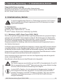
1. General information
■
The field indicators described in the operating instructions have been designed and
manufactured using state-of-the-art technology. All components are subject to stringent
quality and environmental criteria during production. Our management systems are
certified to ISO 9001 and ISO 14001.
■
These operating instructions contain important information on handling the instrument.
Working safely requires that all safety instructions and work instructions are observed.
■
Observe the relevant local accident prevention regulations and general safety
regulations for the instrument‘s range of use.
■
The operating instructions are part of the product and must be kept in the immediate
vicinity of the instrument and readily accessible to skilled personnel at any time.
■
Skilled personnel must have carefully read and understood the operating instructions,
prior to beginning any work.
■
The manufacturer‘s liability is void in the case of any damage caused by using the
product contrary to its intended use, non-compliance with these operating instructions,
assignment of insufficiently qualified skilled personnel or unauthorised modifications to
the instrument.
■
The general terms and conditions contained in the sales documentation shall apply.
■
Subject to technical modifications.
■
Further information:
- Internet address: www.wika.de / www.wika.com
- Relevant data sheet: AC 80.10
- Application consultant: Tel.: +49 9372 132-0
Fax: +49 9372 132-406
info@wika.com
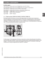
Explanation of symbols
WARNING!
... indicates a potentially dangerous situation which can result in serious injury or
death if not avoided.
CAUTION!
... indicates a potentially dangerous situation which can result in light injuries or
damage to the equipment or the environment if not avoided.
Information
... points out useful tips, recommendations and information for efficient and
trouble-free operation.
1. General information

WIKA operating instructions models DIH50, DIH52
5
EN
14008548.05 12/2016 EN/DE
DANGER!
... identifies hazards caused by electric power. Should the safety instructions not
be observed, there is a risk of serious or fatal injury.
WARNING!
... indicates a potentially dangerous situation in the hazardous area that can
result in serious injury or death, if not avoided.
2. Safety
WARNING!
Before mounting, commissioning and operation, make sure that the display is
suitable for the application.
Non-observance can result in serious injury and/or damage to the equipment.
WARNING!
This is protection class 3 equipment for connection at low voltages, which
are separated from the power supply or voltage by greater than AC 50 V or
DC 120 V. Preferably, a connection to an SELV or PELV circuit is recommended;
alternatively protective measures from HD 60346-4-41 (DIN VDE 0100-410).
Alternatively for North America:
The connection can be made in line with “Class 2 Circuits” or “Class 2 Power
Units” in accordance with CEC (Canadian Electrical Code) or NEC (National
Electrical Code).
Further important safety instructions can be found in the individual chapters of
these operating instructions.
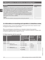
2.1 Intended use
The field indicators models DIH50, DIH52 are used for converting an analogue current
signal (4 … 20 mA) into an indication of the corresponding measured value and are
intended for mounting in the field.
They comprise a display and operating unit without power supply for looping in 4 … 20 mA/
HART
®
circuits.
The instrument has been designed and built solely for the intended use described here,
and may only be used accordingly.
The technical specifications contained in these operating instructions must be observed.
Improper handling or operation of the instrument outside of its technical specifications
requires the instrument to be taken out of service immediately and inspected by an
authorised WIKA service engineer.
1. General information / 2. Safety

6
WIKA operating instructions models DIH50, DIH52
EN
14008548.05 12/2016 EN/DE
If the instrument is moved from a cold into a warm environment, the formation of
condensation may result in the instrument malfunctioning. Before putting it back into
operation, wait for the instrument temperature and the room temperature to equalise.
The manufacturer shall not be liable for claims of any type based on operation contrary to
the intended use.
2.2 Personnel qualification
WARNING!
Risk of injury if qualification is insufficient!
Improper handling can result in considerable injury and damage to equipment.
■
The activities described in these operating instructions may only be carried
out by skilled personnel who have the qualifications described below.
■
Keep unqualified personnel away from hazardous areas.
Skilled personnel
Skilled personnel are understood to be personnel who, based on their technical training,
knowledge of measurement and control technology and on their experience and
knowledge of country-specific regulations, current standards and directives, are capable of
carrying out the work described and independently recognising potential hazards.
Special operating conditions require further appropriate knowledge, e.g. of aggressive
media.
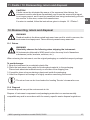
2.3 Additional safety instructions for instruments per ATEX
WARNING!
Non-observance of these instructions and their contents may result in the loss
of explosion protection.
WARNING!
Do not use field indicators with any damage to the exterior!
CAUTION!
■
Repairs are strictly prohibited.
■
Do not use displays presenting externally visible damage.
■
Observe the instructions for mounting and operation as well as the
requirements for the use of the devices in hazardous areas.
2. Safety

WIKA operating instructions models DIH50, DIH52
7
EN
14008548.05 12/2016 EN/DE
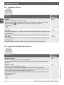
2.4 Special hazards
WARNING!
Observe the information given in the applicable type examination certificate and
the relevant country-specific regulations for installation and use in hazardous
areas (e.g. IEC/EN 60079-14, NEC, CEC). Non-observance can result in serious
injury and/or damage to the equipment.
For further important safety instructions for instruments with ATEX approval, see
chapter 9 “Information on mounting and operation in hazardous areas”.
WARNING!
For hazardous media such as oxygen, acetylene, flammable or toxic gases or
liquids, and refrigeration plants, compressors, etc., in addition to all standard
regulations, the appropriate existing codes or regulations must also be followed.
WARNING!
To ensure safe working on the instrument, the operating company must ensure
■
that suitable first-aid equipment is available and aid is provided whenever
required,
■
that the operating personnel are regularly instructed in all topics regarding
work safety, first aid and environmental protection, and know the operating
instructions, in particular the section on safety instructions.
WARNING!
When working during a running process operation, measures to prevent
electrostatic discharge from the connecting terminals should be taken, as a
discharge could lead to temporary corruption of the measured value.
DANGER!
Danger of death caused by electric current
Upon contact with live parts, there is a direct danger of death.
■
The instrument may only be installed and mounted by skilled personnel.
■
Operation using a defective power supply unit (e.g. short circuit from the
mains voltage to the output voltage) can result in life-threatening voltages at
the instrument!
WARNING!
Residual media in the dismounted instrument can result in a risk to persons, the
environment and equipment. Take sufficient precautionary measures.
2. Safety

8
WIKA operating instructions models DIH50, DIH52
EN
14008548.05 12/2016 EN/DE
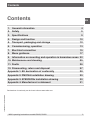
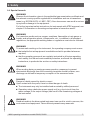
2.5 Labelling, safety marks
■
Product label for whole instrument
DIH50-B
4 ... 20 mA
2-wire
BVS 16 ATEX E 112 X
IECEx BVS 16.0075X
150135
IS, CL 1, DIV 1, Grp. A-D, T4/T5/T6
CL 1, DIV 2, Grp. A-D, T4/T5/T6
T
amb T4/T5/T6: -40 ... +85 °C/+70 °C/+55 °C
Inst. Dwg. 11315741
0158
WARNING! POTENTIAL ELECTROSTATIC CHARGING HAZARD
Made in
Germany
2016
XXXXXXXX
WIKA Alexander Wiegand SE & Co. KG D-63911 Klingenberg
HART
®
2. Safety
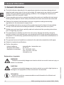
■
Product labels for indicator module
Model
Serial number
Ex marking
Warning note
Year of manufacture
Information on version (output signal, measuring range...)
HART
®
symbol
Logos
FM marking
Installation drawing
Before mounting and commissioning the instrument, ensure you read
the operating instructions!
DIH50-B
4 ... 20 mA
2-wire
BVS 16 ATEX E 112 X
IECEx BVS 16.0075X
150135
IS, CL 1, DIV 1, Grp. A-D, T4/T5/T6
CL 1, DIV 2, Grp. A-D, T4/T5/T6
T
amb T4/T5/T6: -40 ... +85 °C/+70 °C/+55 °C
Inst. Dwg. 11315741
0158
WARNING! POTENTIAL ELECTROSTATIC CHARGING HAZARD
Made in
Germany
2016
XXXXXXXX
WIKA Alexander Wiegand SE & Co. KG D-63911 Klingenberg
HART
®

WIKA operating instructions models DIH50, DIH52
9
EN
14008548.05 12/2016 EN/DE
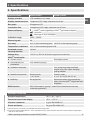
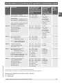
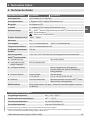
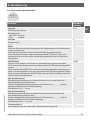
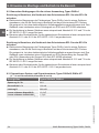
3. Specifications
Specifications Model DIH50 Model DIH52
Display principle LCD, rotatable in 10° steps
Display measured value 7-segment LCD, 5-digit, character size 9 mm
Bar graph 20-segment LCD
Information line 14-segment LCD, 6-digit, character size 5.5 mm
Status indicators
♥
: HART
®
mode (signalling of HART
®
parameter adoption)
: Unit lock
: Warnings or error messages
Indication range -9999 ... 99999
Measuring rate 4/s
Accuracy ±0.1 % of the measuring span ±0.05 % of the measuring span
Temperature coefficient ±0.1 % of the measuring span/10 K
Permitted current
carrying capacity
100 mA
Voltage drop < DC 3 V (< DC 2 V at 20 mA); supply via current loop
HART
®
functionality
■
Access control - Secondary master
■
Automatically set
parameters
Unit, measuring range
■
Available commands - Unit, measuring range start/end,
format, zero point, span, damping,
polling address
■
Identified commands Generic mode:
1, 15, 35, 44
Generic mode:
0, 1, 6, 15, 34, 35, 36, 37, 44
■
Multidrop Not supported Measured values are automatically
taken from the HART
®
digital data and
displayed
EMC directive EN 61326 emission (group 1, class B) and interference immunity
(industrial application)
Ambient conditions
Ambient temperature -60
1)
/ -40 ... +85 °C
Functional area of the display -20
2)
... +70 °C
Vibration resistance 3 g per EN 60068-2-6
Shock resistance 30 g per EN 60068-2-27
3. Specifications
1) Special version on request (only available with selected approvals)
2) In previous ambient temperatures < -20 °C a delayed recovery of the indication function could be expected, especially in
case of low loop current.

10
WIKA operating instructions models DIH50, DIH52
EN
14008548.05 12/2016 EN/DE
Field case
Material Aluminium, stainless steel;
window in polycarbonate
Colour Aluminium: night blue, RAL 5022
Stainless steel: silver
Cable glands 3 x M20 x 1.5 or 3 x ½ NPT
Ingress protection IP66
Weight Aluminium: approx. 1.5 kg
Stainless steel: approx. 3.7 kg
Dimensions see drawing
Basic module Models DIH50-Z, DIH50-B, DIH52-Z, DIH52-B
Material Polycarbonate
Ingress protection IP20
Weight approx. 80 g
Dimensions see drawing
For further specifications see WIKA data sheet AC 80.10 and the order documentation.
For further important safety instructions for operation in hazardous areas, see
chapter 9 “Information on mounting and operation in hazardous areas”.
4. Design and function
4.1 Description
The field indicators are external display and operating units without separate power supply
for 4 … 20 mA/HART
®
sensors. The instruments are used for measured value display and
operation remote from the measuring point. They are looped anywhere in the 4 … 20 mA
signal line and measure the current in the current loop. At the same time, they read and
display the measured values with unit via the HART
®
signal.
The field indicators are powered directly from the 4 ... 20 mA current loop, with a resultant
voltage drop of less than 3 V.
The field indicators meet the requirements of:
■
Explosion protection (depending on the version)
■
Electromagnetic compatibility in accordance with DIN EN 61326 and NAMUR
recommendation NE21
3. Specifications / 4. Design and function

WIKA operating instructions models DIH50, DIH52
11
EN
14008548.05 12/2016 EN/DE
Versions
Model DIH5x-Z Basic module without field case, no Ex protection
Model DIH5x-B Basic module without field case, Ex protection (intrinsically safe)
Model DIH5x-S Field indicator, no Ex protection (standard)
Model DIH5x-F Field indicator, Ex protection (flameproof enclosure)
Model DIH5x-I Field indicator, Ex protection (intrinsically safe)
Model DIH50 HART
®
slave (standard)
Model DIH52 HART
®
master
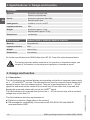
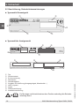
4.1.1 Basic module (DIH50-B, DIH50-Z, DIH52-B, DIH52-Z)
The basic modules comprise a mounting adapter with two integrated connection terminals
and connecting cables, as well as a display unit including the display and the electronics.
Both parts are connected via a cable with plug-in coupling. Depending on their design, the
basic modules can be mounted in different cases or thermometer connection heads.
Use cases suitable for field mounting which comply with the valid regulations and
requirements. In particular, observe the ambient conditions defined in chapter 3
“Specifications” and the requirements defined in chapter 9 “Information on mounting and
operation in hazardous areas”.
1920741.01
4. Design and function

12
WIKA operating instructions models DIH50, DIH52
EN
14008548.05 12/2016 EN/DE
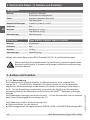
4.1.2 Field indicators (DIH5x-S, DIH5x-I, DIH5x-F)
The field indicators comprise a case with integrated display and operation module and a
terminal insert with two terminal blocks.
4.2 Operation in safety-related applications
The field indicators are suitable for use in safety-related applications (required
characteristics see Appendix 4 “Manufacturer's statement”).
4.3 Scope of delivery
Cross-check the scope of delivery with the delivery note.
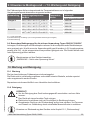
5. Transport, packaging and storage
5.1 Transport
Check the instrument for any damage that may have been caused by transport.
Obvious damage must be reported immediately.
5.2 Packaging
Do not remove packaging until just before mounting.
Keep the packaging as it will provide optimum protection during transport (e.g. change in
installation site, sending for repair).
5.3 Storage
Permissible conditions at the place of storage:
■
Storage temperature: -40 ... +85 °C
■
Humidity: 35 ... 85 % relative humidity (without condensation)
1556707.01
4. Design and function / 5. Transport, packaging and storage

WIKA operating instructions models DIH50, DIH52
13
EN
14008548.05 12/2016 EN/DE
Avoid exposure to the following factors:
■
Direct sunlight or proximity to hot objects
■
Mechanical vibration, mechanical shock (putting it down hard)
■
Soot, vapour, dust and corrosive gases
6. Commissioning, operation
In hazardous areas, only use field indicators that are approved for those
hazardous areas. The approval is marked on the product label.
6.1 Operating modes
The following operating modes are possible:
■
HART
®
slave / basic mode (4 ... 20 mA)
■
HART
®
master / basic mode / multidrop (model DIH52)
6.1.1 Operating mode: HART
®
slave (models DIH50, DIH52)
The digital indicators powered via the same current loop as the corresponding transmitters
monitor permanently the HART
®
communication. When modifying the unit or measuring
range of the connected transmitter, the unit of the digital indicator and the corresponding
indication range are adapted automatically.
However, it is required that the unit set in the transmitter is also set in the devices.
A flashing ♥ symbol is shown on the display when a HART
®
communication takes place for
the first time and the digital indicators are thus switched to the HART
®
mode. The ♥ symbol
is displayed permanently when the HART
®
communication is terminated and the digital
indicator is configured according to the measuring range and the unit of the connected
transmitter.
After the power supply was interrupted or the digital indicator was set manually, the ♥
symbol is no longer displayed.
During operation in the basic mode, the ♥ symbol is not displayed.
CAUTION!
The instruments react only to the HART
®
standard commands 15 and 35. If
a connected HART
®
transmitter is configured by means of other commands,
automatic setting is not possible!
The HART
®
function, i.e. the automatic adaptation of the display to the
configured data of the transmitter, requires a HART
®
communication between
the transmitter and the HART
®
software (e.g. WIKA_T32) or between the
transmitter and the field communicator (e.g. FC375/FC475, MFC4150 etc.).
5. Transport, packaging ... / 6. Commissioning, operation

14
WIKA operating instructions models DIH50, DIH52
EN
14008548.05 12/2016 EN/DE
6.1.2 Operating mode: HART
®
master (model DIH52)
The master mode enables the modification of the measuring range, the unit, the format,
the damping and the polling address of the connected HART
®
transmitter. Further
modifications to the configuration of the transmitter (e.g. selection of the sensor) are not
possible.
During the starting procedure, the field indicators try to contact the connected HART
®
transmitter in the master mode and to apply its settings (unit and measuring range). During
the connection establishment, the status line shows the message “Connecting HART
®”
.
When a HART
®
sensor is detected, the HART
®
symbol is displayed. The field indicator
switches to the HART
®
mode and starts operation using the settings received from the
transmitter. This procedure is repeated whenever the power supply is switched on.
When pressing any key during the starting process or the device has not detected any
HART
®
transmitter during approx. 70 seconds, the digital indicator switches to the basic
mode and starts operation on the basis of the factory settings.
6.1.3 Operating mode: Multidrop (model DIH52)
In this specially defined operating state for HART
®
transmitters, the current signal is firmly
set to 4 mA and the measuring information is transmitted via the HART
®
communication
to the control room. To enable the displaying of the measured value of a transmitter, the
address of the desired transmitter must be set in the "Address" menu item.
If the HART
®
address is modified during operation, the establishment of a new connection
is started during which, however, the sensor must respond immediately in order to
complete the connection establishment.
The digital indicators show the measured values of the primary variable transmitted via
HART
®
to the control room. The display is passive, i.e. the transmission of the measured
values must be requested by the control room. The devices function as secondary master
with respect to the sensor during the parameterisation.
6.1.4 Operating mode: Basic mode, 4 ... 20 mA (models DIH50, DIH52)
In the basic mode, all settings of the digital indicator must be carried out manually by
means of the front-side keys.
To navigate in the menu levels, four keys with the following functions are available:
▲ (UP) One menu item up
▼ (DOWN) One menu item down
OK Calls the programming menu
ESC Exits the programming menu
- Back to the previous menu level in the menu guidance
- Return from the edit function without saving the modification
see also chapter 8 “Menu guidance”
6. Commissioning, operation

WIKA operating instructions models DIH50, DIH52
15
EN
14008548.05 12/2016 EN/DE
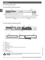
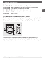
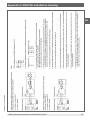
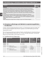
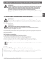
6.2 User interface
7. Electrical connection
WARNING!
Observe the safety-relevant maximum values for the connection of the power
supply and the sensors defined in chapter 9.1 “Model overview and their
approvals”.
When working on the field indicators (e.g. installation/removal, maintenance work) take
measures to prevent electrostatic discharge from the terminals.
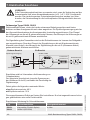
WARNING!
Carry out mounting work only with power disconnected!
Use the recommended cables and tighten the cable gland. Lead the connecting cable
downward before of the cable gland in order to provide additional protection of the device
against penetration of liquids. Rain water and condensed water can thus drip.
The device is connected by means of a commercially available two-wire cable without
screen. If electromagnetic interference exceeding the test values of EN 61326 for industrial
areas is to be expected or the HART
®
multidrop mode is used, a screened cable must
be used. Use cables with round cross section. An outside diameter of cable of 5 ... 9 mm
(0.2 … 0.35 inch) guarantees the tightness of the cable gland. When using other diameters
or cross sections, the gasket must be replaced or a suitable cable gland must be used.
Connect the cable screen on both sides to earth potential if a screened cable is required.
Connect the screen in the sensor directly to the internal earth terminal. The external earth
terminal of the case must be connected with low impedance to the equipotential bonding.
Status data
Operating keys
Unit line, info line
Bar graph
Measured value
6. Commissioning, operation / 7. Electrical connection

16
WIKA operating instructions models DIH50, DIH52
EN
14008548.05 12/2016 EN/DE
CAUTION!
If equipotential bonding currents are to be expected, a ceramic capacitor
(e.g. 1 nF, 1,500 V) must be used for the connection on the evaluation side. The
low-frequency equipotential bonding currents are thus suppressed, but the
high-frequency interference signals remain.
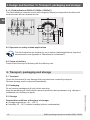
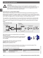
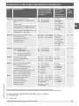
Field indicators models DIH50, DIH52
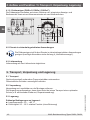
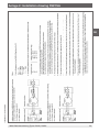
Open the case cover, push one of the two black fastening clips backwards and pull the
display module upwards. The power supply is connected at the front via the Philips screws
of the display module. Connect the positive pole of the power supply to the terminal marked
with ⊕ and the negative pole of the power supply to the terminal marked with ⊖.
The signal line of the transmitter is to be connected to the terminal blocks inside the field
case. To do so, connect the positive pole of the signal line to the terminal marked with ⊕
(red cable) and the negative pole of the signal line to the terminal marked with ⊖ (black
cable).
With flexible leads we recommend the use of crimped
connector sleeves.
The integrated reverse polarity protection (wrong polarity
on the terminals ⊕ and ⊖) prevents the digital indicator
from damage.
The following maximum values are applicable:
without explosion protection: 42 V
with explosion protection: 30 V
The connected wires must be checked to ensure they are connected properly. Only
well-secured wires can guarantee a fault-free operation.
Recommended tools for terminal screws:
Model Screwdriver Tightening torque
DIH50,
DIH52
Cross head ('Pozidriv' tip)
size 2 (ISO 8764)
0.4 Nm
Non-hazardous area
Ex area
black
spring-loaded
push terminals
Voltage supply
Load
Transmitter
DIH50, DIH52
red
7. Electrical connection

WIKA operating instructions models DIH50, DIH52
17
EN
14008548.05 12/2016 EN/DE
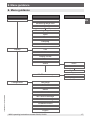
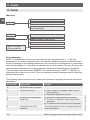
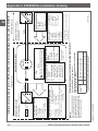
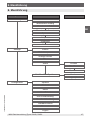
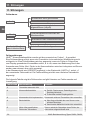
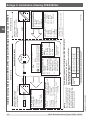
8. Menu guidance
8. Menu guidance
Main menu Submenu 1 Submenu 2
Measurement
Display
Configuration
Unit
Measuring range start
Measuring range end
Measuring range format
Unit
Unit lock
Display format
Filter
Alarm
Min/Max memory
Language
Contrast
Reset
User unit
Min. failure message
Max. failure message
Firmware version
on/off
Low alarm
High alarm
delete
display yes/no
Span
Zero
Damping
Adress
Password
Logout

18
WIKA operating instructions models DIH50, DIH52
EN
14008548.05 12/2016 EN/DE
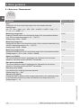
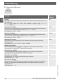
8.1 Main menu “Measurement”
Function Factory setting
Unit
Setting the unit of the measuring range of the connected transmitter
Setting range:
mA → Ω → bar → mbar → psi → hPa → kPa → mmH2O → mH2O → inHg → °C →
°F → K → % → USER → V
mA
Measuring range start
Setting of the start value of the measuring range of the connected transmitter
(e.g. -30 for a measuring range of -30 ... +120 °C)
Setting range: -9999 ... 99999
4,000
Measuring range end
Setting the end value of the measuring range of the connected transmitter (e.g.
120 for a measuring range of -30 ... +120 °C)
Setting range: -9999 ... 99999
20,000
Measuring range format
Setting the decimal point for the measuring range of the connected transmitter.
Setting range: 0 ↔ 0.0 ↔ 0.00 ↔ 0.000 ↔ 0.0000
0.000
Span (only DIH52)
The current measured value is applied as max. adjustment for the sensor.
Attention: Cannot be used for all HART
®
transmitters
-----
Zero point (only DIH52)
The current measured value is applied as min. adjustment for the sensor.
Attention: Cannot be used for all HART
®
transmitters
-----
Damping (only DIH52)
Input damping for damping the measured value.
Setting range: 0.0 … 999
0.0
Adress (only DIH52)
Setting the HART
®
address of the assigned transmitter in the multidrop mode;
for the standard current loop mode, this address must always be set to 0.
Setting range: 0 ... 15
0
8. Menu guidance

WIKA operating instructions models DIH50, DIH52
19
EN
14008548.05 12/2016 EN/DE
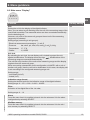
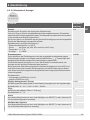
8.2 Main menu “Display”
Function Factory setting
Unit
Setting the unit for the display of the digital indicator
Here, you can select a unit deviating from the unit of the measuring range of the
connected transmitter. The measured values are then converted automatically
into the deviating unit.
However, only units of the same unit group as the set unit of the measuring
range may be selected.
Setting range (according to unit groups):
- Electrical measurement parameters: V, mA, Ω
- Pressure: bar, mbar, psi, hPa, kPa, mmH
2
O, mH
2
O, inHg
- Temperature: °C, °F, K
- Others: %, USER
mA
Unit lock
By activating the unit lock, the set display unit is locked to protect the unit
against modifications. The display shows the sign . Modifications of the
measuring range are converted automatically.
The unit lock only functions if the units of the measuring range and the display
originate from the same unit group.
When connecting a transmitter and its configuration via HART
®
with a unit of
another unit group, then the unit lock is deactivated. In this case, the display unit
is set according to the configured measuring range unit.
Setting range:
- not locked (UnLoC)
- locked (LoC)
UnLoC
Indication range format
Setting the decimal point for the indication range of the digital indicator
Setting range: 0 ↔ 0.0 ↔ 0.00 ↔ 0.000 ↔ 0.0000
0.000
Filter
Activation of the digital filter of the 1st order;
Setting range: 0 ... 10
0
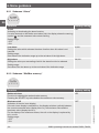
Alarm
From this menu item it is possible to branch into the submenu 2 for the alarm
configuration by selecting SELECT.
-----
Min/Max memory
From this menu item it is possible to branch into the submenu 2 for the min./
max. memory by selecting SELECT.
-----
8. Menu guidance

20
WIKA operating instructions models DIH50, DIH52
EN
14008548.05 12/2016 EN/DE
Function Factory setting
On/off
Activating or deactivating the alarm function;
if a value exceeds or falls below a set alarm limit, the display shows the warning
symbol and the measured value starts flashing.
Setting range:
- OFF
- ON
OFF
Low alarm
Setting the value which releases the alarm function when this value is not
reached.
Setting range:
Start value of the indication range up to the set value of the high alarm
4,000
High alarm
Setting the value upon exceeding of which the alarm function is released.
Setting range:
Set value of the low alarm up to the end value of the indication range
20,000
8.2.2 Submenu “Min/Max memory"
Function Factory setting
Delete min/max
Function for deleting the maximal value memory
Pressing the SELECT key twice deletes the maximum value memory.
dEL
Min/max on/off
Activation of the min./max. display;
If the min./max. display is switched on, the display switches cyclically between
the current measured value (display time 5 s), the minimum value and the
maximum value (display time 2 s).
For the display of the maximum values, the unit on the display is replaced by
min. or max.
Setting range:
- OFF
- ON
OFF
8.2.1 Submenu “Alarm”
8. Menu guidance
Seite wird geladen ...
Seite wird geladen ...
Seite wird geladen ...
Seite wird geladen ...
Seite wird geladen ...
Seite wird geladen ...
Seite wird geladen ...
Seite wird geladen ...
Seite wird geladen ...
Seite wird geladen ...
Seite wird geladen ...
Seite wird geladen ...
Seite wird geladen ...
Seite wird geladen ...
Seite wird geladen ...
Seite wird geladen ...
Seite wird geladen ...
Seite wird geladen ...
Seite wird geladen ...
Seite wird geladen ...
Seite wird geladen ...
Seite wird geladen ...
Seite wird geladen ...
Seite wird geladen ...
Seite wird geladen ...
Seite wird geladen ...
Seite wird geladen ...
Seite wird geladen ...
Seite wird geladen ...
Seite wird geladen ...
Seite wird geladen ...
Seite wird geladen ...
Seite wird geladen ...
Seite wird geladen ...
Seite wird geladen ...
Seite wird geladen ...
Seite wird geladen ...
Seite wird geladen ...
Seite wird geladen ...
Seite wird geladen ...
Seite wird geladen ...
Seite wird geladen ...
Seite wird geladen ...
Seite wird geladen ...
-
 1
1
-
 2
2
-
 3
3
-
 4
4
-
 5
5
-
 6
6
-
 7
7
-
 8
8
-
 9
9
-
 10
10
-
 11
11
-
 12
12
-
 13
13
-
 14
14
-
 15
15
-
 16
16
-
 17
17
-
 18
18
-
 19
19
-
 20
20
-
 21
21
-
 22
22
-
 23
23
-
 24
24
-
 25
25
-
 26
26
-
 27
27
-
 28
28
-
 29
29
-
 30
30
-
 31
31
-
 32
32
-
 33
33
-
 34
34
-
 35
35
-
 36
36
-
 37
37
-
 38
38
-
 39
39
-
 40
40
-
 41
41
-
 42
42
-
 43
43
-
 44
44
-
 45
45
-
 46
46
-
 47
47
-
 48
48
-
 49
49
-
 50
50
-
 51
51
-
 52
52
-
 53
53
-
 54
54
-
 55
55
-
 56
56
-
 57
57
-
 58
58
-
 59
59
-
 60
60
-
 61
61
-
 62
62
-
 63
63
-
 64
64


WIKA DIH50 tag:model:DIH52 Bedienungsanleitung
- Typ
- Bedienungsanleitung
in anderen Sprachen
Verwandte Artikel
-
WIKA E-10 tag:model:E-11 Bedienungsanleitung
-
-
-
-
-
-
WIKA UPT-20 tag:model:UPT-21 Bedienungsanleitung
-
-
-
Andere Dokumente
-
Dynisco SPXD Benutzerhandbuch
-
Pepperl+Fuchs OCS2000-M1K-N2 Bedienungsanleitung
-
IFM PS308A Bedienungsanleitung
-
-
ABB 266DLH Operating Instructions Manual
-
 Kübler Codix 532 Benutzerhandbuch
-
Baumer Connection cable Datenblatt
-
Exor eX705 Installationsanleitung
-
Exor eX7xx Touch Panel 7 Inch PCAP Multitouch Installationsanleitung
-
Dwyer Instruments PMT2-05-A-U2 Benutzerhandbuch
