
Operating instructions
Betriebsanleitung
Mode d‘emploi
Manual de instrucciones
EN
DE
FR
ES
Intrinsically safe submersible pressure transmitter model IL-10
Eigensichere Pegelsonde Typ IL-10
Only for instruments with the following marking:
BVS 10 ATEX E 126 X
IECEx BVS 10.0077X
Transmetteur de pression immergeable à sécurité intrinsèque type IL-10
Sonda de pozo con seguridad intrínseca modelo IL-10

2 WIKA operating instructions submersible pressure transmitter model IL-10
EN
DE
14161955.03 01/2019 EN/DE/FR/ES
ES
FR
© 06/2016 WIKA Alexander Wiegand SE & Co. KG
All rights reserved. / Alle Rechte vorbehalten.
WIKA
®
is a registered trademark in various countries.
WIKA
®
ist eine geschützte Marke in verschiedenen Ländern.
Prior to starting any work, read the operating instructions!
Keep for later use!
Vor Beginn aller Arbeiten Betriebsanleitung lesen!
Zum späteren Gebrauch aufbewahren!
Lire le mode d‘emploi avant de commencer toute opération !
A conserver pour une utilisation ultérieure !
¡Leer el manual de instrucciones antes de comenzar cualquier trabajo!
¡Guardar el manual para una eventual consulta!
Operating instructions model IL-10 Page 3 - 26
Betriebsanleitung Typ IL-10 Seite 27 - 50
Mode d‘emploi type IL-10 Página 51 - 74
Manual de instrucciones modelo IL-10 Page 75 - 99

3WIKA operating instructions submersible pressure transmitter model IL-10
14161955.03 01/2019 EN/DE/FR/ES
EN
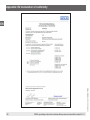
Declarations of conformity can be found online at www.wika.com.
Contents
Contents
1. General information 4
2. Design and function 6
3. Safety 7
4. Transport, packaging and storage 15
5. Commissioning, operation 16
6. Faults 19
7. Maintenance and cleaning 21
8. Dismounting, return and disposal 22
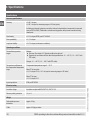
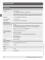
9. Specications 23
Appendix: EU declaration of conformity 26

4 WIKA operating instructions submersible pressure transmitter model IL-10
14161955.03 01/2019 EN/DE/FR/ES
EN
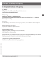
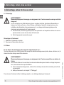
1. General information
■
The submersibel pressure transmitter described in the operating instructions has been designed and manufactured
using state-of-the-art technology. All components are subject to stringent quality and environmental criteria during
production. Our management systems are certied to ISO 9001 and ISO 14001.
■
These operating instructions contain important information on handling the instrument. Working safely requires that
all safety instructions and work instructions are observed.
■
Observe the relevant local accident prevention regulations and general safety regulations for the instrument's range
of use.
■
The operating instructions are part of the product and must be kept in the immediate vicinity of the instrument and
readily accessible to skilled personnel at any time.
■
Skilled personnel must have carefully read and understood the operating instructions prior to beginning any work.
■
The manufacturer's liability is void in the case of any damage caused by using the product contrary to its intended
use, non-compliance with these operating instructions, assignment of insuciently qualied skilled personnel or
unauthorised modications to the instrument.
■
The general terms and conditions contained in the sales documentation shall apply.
■
Subject to technical modications.
■
Further information:
- Internet address: www.wika.de / www.wika.com
- Relevant data sheet: PE 81.23
- Application consultant: Tel.: +49 9372 132-0
Fax: +49 9372 132-406
E-mail: [email protected]
1. General information

5WIKA operating instructions submersible pressure transmitter model IL-10
14161955.03 01/2019 EN/DE/FR/ES
EN
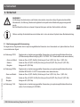
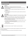
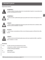
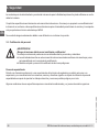
Explanation of symbols
WARNING!
... indicates a potentially dangerous situation in the hazardous area that can result in serious injury or
death, if not avoided.
WARNING!
... indicates a potentially dangerous situation that can result in serious injury or death, if not avoided.
CAUTION!
... indicates a potentially dangerous situation that can result in light injuries or damage to equipment or
the environment, if not avoided.
Information
... points out useful tips, recommendations and information for ecient and trouble-free operation.
CAUTION!
... indicates a potentially dangerous situation that can result in burns, caused by hot surfaces or liquids,
if not avoided.
Abbreviations
2-wire Two connection lines are used for the voltage supply.
The measurement signal also provides the supply current.
U+ Positive supply terminal
S+ Analogue output
U- / 0V Negative power supply terminal
1. General information

6 WIKA operating instructions submersible pressure transmitter model IL-10
14161955.03 01/2019 EN/DE/FR/ES
EN
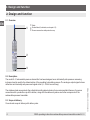
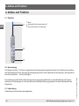
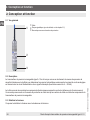
2. Design and function
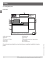
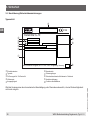
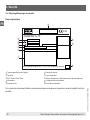
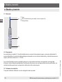
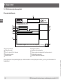
2.1 Overview
2.2 Description
The model IL-10 submersible pressure transmitter has been designed as an intrinsically safe pressure measuring
instrument and is used for the determination of the prevailing hydrostatic pressure. The analogue output signal is trans-
mitted via an intrinsically safe power and signal circuit (4 ... 20 mA current loop).
The stainless steel case protects the potted intrinsically safe electronics from environmental inuences. A process
connection with a protection cap at the bottom, along with the cable entry above are further components of the
submersible pressure transmitter.
2.3 Scope of delivery
Cross-check scope of delivery with delivery note.
2. Design and function
Cable
Product label (for details, see chapter 3.5)
Process connection with protection cap

7WIKA operating instructions submersible pressure transmitter model IL-10
14161955.03 01/2019 EN/DE/FR/ES
EN
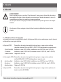
3. Safety
3. Safety
WARNING!
Before installation, commissioning and operation, ensure that the appropriate submersible pressure
transmitter has been selected in terms of measuring range, design, media compatibility and specic
measuring conditions.
Non-observance can result in serious injury and/or damage to the equipment.
Further important safety instructions can be found in the individual chapters of these operating
instructions.
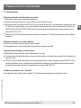
3.1 Intended use
The intrinsically safe submersible pressure transmitter is used in hazardous areas to convert hydrostatic pressure into
an electrical signal.
■
ATEX approval: Submersible pressure transmitter approved for use in hazardous areas (EU-type examination
certicate BVS 10 ATEX E 126 X downloadable from www.wika.com).
- Gases and mist: Mounting to zone 0 (EPL Ga/Gb); installation in zone 0 (EPL Ga), zone 1 (GPL Gb)
- Dusts: Mounting to zone 20 (EPL Da/Db); installation in zone 20 (EPL Da), zone 21 (EPL Db)
- Mining: Category M1 (EPL Ma)
■
IECEx approval: Submersible pressure transmitter approved for use in hazardous areas (certicate
IECEx BVS 10.0077X downloadable from www.wika.com).
- Gases and mist: Mounting to zone 0 (EPL Ga/Gb); installation in zone 0 (EPL Ga), zone 1 (GPL Gb)
- Dusts: Mounting to zone 20 (EPL Da/Db); installation in zone 20 (EPL Da), zone 21 (EPL Db)
- Mining: Category M1 (EPL Ma)
■
CSA approval: Submersible pressure transmitter approved for use in hazardous areas (see control drawing
no. 2323880)

8 WIKA operating instructions submersible pressure transmitter model IL-10
14161955.03 01/2019 EN/DE/FR/ES
EN
The submersible pressure transmitter has been designed and built solely for the intended use described here, and may
only be used accordingly.
The technical specications contained in these operating instructions must be observed. Improper handling or operati-
on of the instrument outside of its technical specications requires the instrument to be taken out of service immediate-
ly and inspected by an authorised WIKA service engineer.
The manufacturer shall not be liable for claims of any type based on operation contrary to the intended use.
3.2 Personnelqualication
WARNING!
Riskofinjuryshouldqualicationbeinsucient!
Improper handling can result in considerable injury and damage to equipment.
■
The activities described in these operating instructions may only be carried out by skilled personnel
who have the qualications described below.
■
Keep unqualied personnel away from hazardous areas.
Skilled personnel
Skilled personnel are understood to be personnel who, based on their technical training, knowledge of measurement
and control technology and on their experience and knowledge of country-specic regulations, current standards and
directives, are capable of carrying out the work described and independently recognising potential hazards.
Special operating conditions require further appropriate knowledge, e.g. of aggressive media.
3. Safety

9WIKA operating instructions submersible pressure transmitter model IL-10
14161955.03 01/2019 EN/DE/FR/ES
EN
3. Safety
3.3 Special conditions for safe use (ATEX and IECEx)
WARNING!
Non-observance of these instructions and their contents may result in the loss of explosion protection.
Gas application
■
The installation of the submersible pressure transmitter into the wall between areas that require EPL Ga equipment
must be made in such a way that ingress protection IP67 in accordance with EN 60529 is ensured.
■
When using the submersible pressure transmitter in areas that require EPL Ga, the shield of the connection lead
and the metallic part of the strain relief clamp must be included within the equipotential bonding of the vessel.
■
The tting of the cable entry of the instrument into the wall that separates areas with EPL Ga requirements from
less-hazardous areas must be made in such a way that ingress protection IP67 in accordance with EN 60529 is
ensured.
■
Observe the manufacturer's technical information for the use of the submersible pressure transmitter in combination
with aggressive and corrosive media and for avoiding mechanical hazards.
Dust applications
■
The submersible pressure transmitter must be mounted into the wall between areas that require EPL Da in such a
way that ingress protection IP6X in accordance with IEC 60529 is ensured.
■
When using the submersible pressure transmitter in areas that require EPL Da, the shield of the connection lead
and the metallic part of the strain relief clamp must be included within the equipotential bonding of the vessel.
■
The tting of the cable entry of the submersible pressure transmitter into the wall that separates areas with EPL Da
requirements from less-hazardous areas must be made in such a way that ingress protection IP6X in accordance
with EN 60529 is ensured.
■
Observe the manufacturer‘s technical information for the use of the submersible pressure transmitter in combination
with aggressive and corrosive media and for avoiding mechanical hazards.

10 WIKA operating instructions submersible pressure transmitter model IL-10
14161955.03 01/2019 EN/DE/FR/ES
EN
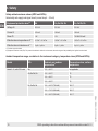
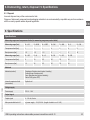
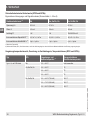
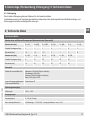
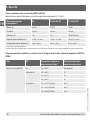
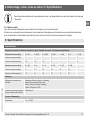
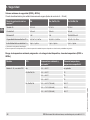
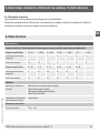
Safety-related maximum values (ATEX and IECEx)
Intrinsically safe supply and signal circuit (current loop 4 ... 20 mA)
Equipment protection level
2)
Ma Ga, Ga/Gb, Gb Da, Da/Db, Db
Voltage Ui
DC 30 V DC 30 V DC 30 V
Current Ii
100 mA 100 mA 100 mA
Power Pi
1 W 1 W 750/650/550 mW
Eective internal capacitance Ci
1)
16.5 nF + 0.1 nF/m 16.5 nF + 0.1 nF/m 16.5 nF + 0.1 nF/m
Eective internal inductance Li
1)
0 µH + 1 µH/m 0 µH + 1 µH/m 0 µH + 1 µH/m
1) For value see product label
2) Equipment Protection Level (EPL): The protection level that is dened for an instrument, where the degree of the probability of an ignition forms the basis.
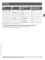
Ambient temperature range, correlation to the instrument category, temperature class (ATEX and IECEx)
Model EPL Ambient and medium
temperature
1)
Temperature class, surface
temperature
Model IL-10, with PUR cable Ma -30 ... +80 °C not applicable
Ga, Ga/Gb, Gb -30 ... +60 °C T6
-30 ... +80 °C T5
-30 ... +80 °C T4
Da, Da/Db, Db -30 ... +40 °C (750 mW) 120 °C
-30 ... +70 °C (650 mW) 120 °C
-30 ... +80 °C (550 mW) 120 °C
3. Safety

11WIKA operating instructions submersible pressure transmitter model IL-10
14161955.03 01/2019 EN/DE/FR/ES
EN
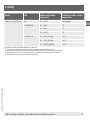
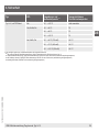
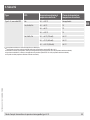
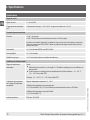
Model EPL Ambient and medium
temperature
1)
Temperature class, surface
temperature
Model IL-10, with FEP cable Ma -30 ... +105 °C not applicable
Ga, Ga/Gb, Gb -30 ... +60 °C T6
-30 ... +80 °C T5
-30 ... +105 °C T4
Da, Da/Db, Db -30 ... +40 °C (750 mW) 120 °C
-30 ... +70 °C (650 mW) 120 °C
-30 ... +100 °C (550 mW) 120 °C
1) The respective ambient and medium temperatures are limited by:
■
The maximum permissible surface temperature, valid for applications that require EPL Ma (150 °C)
■
Temperature class assignment, valid for gas applications that require EPL Ga or Gb (maximum ambient temperature)
■
The permissible power, Pi, valid for dust applications that require EPL Da or Db (maximum ambient temperature)
■
Cable properties (minimum and maximum ambient temperature)
3. Safety

12 WIKA operating instructions submersible pressure transmitter model IL-10
14161955.03 01/2019 EN/DE/FR/ES
EN
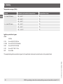
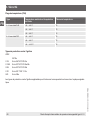
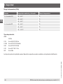
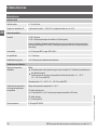
Temperature range (CSA)
Model Ambient and medium temperature Temperature class
IL-10 with PUR cable -20 ... +60 °C T6
-20 ... +80 °C T5
-20 ... +80 °C T4
IL-10 with FEP cable -20 ... +60 °C T6
-20 ... +80 °C T5
-20 ... +105 °C T4
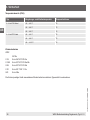
Ignition protection types
ATEX
IECEx
II 1G Ex ia IIA T4/T5/T6 Ga
II 1/2G Ex ia IIC T4/T5/T6 Ga/Gb
II 2G Ex ia IIC T4/T5/T6 Gb
II 1D Ex ia IIIC T120 °C Da
I M1 Ex ia I Ma
The applicable ignition protection types for the particular instrument can be found on the product label.
3. Safety

13WIKA operating instructions submersible pressure transmitter model IL-10
14161955.03 01/2019 EN/DE/FR/ES
EN
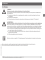
3.4 Special hazards
WARNING!
Observe the information given in the applicable EC-type examination certicate and the relevant
country-specic regulations for installation and use in hazardous areas (e.g. IEC 60079-14, NEC, CEC).
Non-observance can result in serious injury and/or damage to the equipment.
WARNING!
For hazardous media such as oxygen, acetylene, ammable or toxic gases or liquids, and refrigeration
plants, compressors, etc., in addition to all standard regulations, the appropriate existing codes or
regulations must also be followed.
WARNING!
Residual media on submersible pressure transmitters can result in a risk to persons, the environment
and equipment.
Take sucient precautionary measures.
Do not use this instrument in safety or emergency stop devices. Incorrect use of the instrument can
result in injury.
3. Safety

14 WIKA operating instructions submersible pressure transmitter model IL-10
14161955.03 01/2019 EN/DE/FR/ES
EN
3. Safety
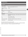
3.5 Labelling/Safety marks
Product label
Transmitter IL-10
WIKA Alexander Wiegand SE & Co. KG 63911 Klingenberg Germany
0158
Ignition protection types
Measuring range
Model code
Approval logos
P# Product no. / S# Serial no.
Safety-related maximum values / ingress protection
Power supply
Pin assignment
Output signal
Code manufacture date
If the serial number becomes illegible due to mechanical damage or overpainting, traceability will no longer be
possible.

15WIKA operating instructions submersible pressure transmitter model IL-10
14161955.03 01/2019 EN/DE/FR/ES
EN
4. Transport, packaging and storage
4. Transport, packaging and storage
4.1 Transport
Check the submersible pressure transmitter for any damage that may have been caused by transport.
Obvious damage must be reported immediately.
4.2 Packaging
Do not remove packaging until just before mounting.
Keep the packaging as it will provide optimum protection during transport (e.g. change in installation site, sending for
repair).
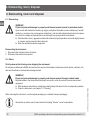
4.3 Storage
If the protection cap is not mounted, it should be mounted for storage so that the diaphragm will not be damaged.
Permissible conditions at the place of storage:
Storage temperature: See chapter 9 “Specications”
Avoid exposure to the following factors:
■
Mechanical vibration, mechanical shock (putting it down hard)
■
Soot, vapour, dust and corrosive gases
Store the submersible pressure transmitter in its original packaging in a location that fulls the conditions listed above.
If the original packaging is not available, pack and store the instrument as described below:
1. Wrap the instrument in an antistatic plastic lm.
2. Place the instrument, along with shock-absorbent material, in the packaging.

16 WIKA operating instructions submersible pressure transmitter model IL-10
14161955.03 01/2019 EN/DE/FR/ES
EN
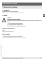
5. Commissioning, operation
5. Commissioning, operation
5.1 Mechanical mounting
5.1.1 Safety inspection
Only use the instrument if it is in perfect condition with respect to safety.
■
Prior to commissioning, the instrument must be subjected to a visual inspection.
■
Leaking uid is indicative of damage.
■
With a damaged diaphragm, explosion protection cannot be guaranteed.
5.1.2 Requirements for the mounting point
The existence of strong electromagnetic elds in a frequency range of < 2.7 GHz can result in increased measuring
errors up to 1 % of span. Do not install the instruments in the vicinity of strong electromagnetic sources of interference
(e.g. transmitting devices, radio equipment), or use sheath current lters where applicable.
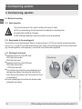
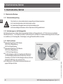
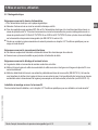
5.1.3 Mounting the instrument
■
Maximum tensile force of the FEP cable:
350 N without strain relief
500 N with strain relief
■
Maximum tensile force of the PUR cable:
350 N without strain relief
1,000 N with strain relief
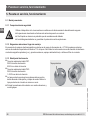
■
The protection cap protects the internal diaphragm from
damage during transport and during the lowering of the
probe. Remove the protection cap if the medium is viscous
or contaminated.
■
Protect the diaphragm from contact with abrasive media
and against any impacts.
Protection cap
Diaphragm

17WIKA operating instructions submersible pressure transmitter model IL-10
14161955.03 01/2019 EN/DE/FR/ES
EN
5. Commissioning, operation
5.2 Electrical mounting
Requirements for voltage supply
→ For power supply see product label
■
Power the instrument via a certied intrinsically safe circuit.
■
For applications that require EPL Gb or Db, the power supply and signal circuit should have a protection level of “ib”.
Then the interconnections and thus the submersible pressure transmitter will have a protection level of II 2G Ex ib
IIC T4/T5/T6 Gb or II 2D Ex ib IIIC T4/T5/T6 Db, although the submersible pressure transmitter is marked otherwise
(see EN 60079-14 section 5.4).
■
Note the safety-related maximum values in chapter 3.3 “Special conditions for safe use”.
Requirements for electrical connection
■
Fine-stranded leads with bare ends must be nished with end splices.
■
Make sure that no moisture enters at the cable end.
Requirements for shielding and grounding
■
The cable shield is connected conductively with the case.
■
Ground the cable shield at least at one end of the cable, if the lines are longer than 30 m or leave the building.
■
Ground the cable shield at one end, preferably in the non-Ex area (EN 60079-14). The simultaneous connection of
the case and the cable shield to ground is only permitted if any accidental energisation between the shield connec-
tion (e.g. at the isolated barrier) and the case can be excluded (see EN 60079-14).
Installation and mounting to zone 0 and zone 20
For mounting instructions, see chapter 3.3 “Special conditions for safe use”.

18 WIKA operating instructions submersible pressure transmitter model IL-10
14161955.03 01/2019 EN/DE/FR/ES
EN
Connection diagram
Cable outlet shielded
U+ brown
U- green
Shield grey (connected to case)
Conductor cross-section 0.25 mm²
Conductor outer diameter 7.5 mm
5.3 Functional check
The output signal must be proportional to the prevailing pressure. If this is not the case, this may indicate a damaged
diaphragm.
In this case, see chapter 6 “Faults”.
5. Commissioning, operation

19WIKA operating instructions submersible pressure transmitter model IL-10
14161955.03 01/2019 EN/DE/FR/ES
EN
6. Faults
6. Faults
CAUTION!
Physical injuries and damage to property and the environment
If faults cannot be eliminated by means of the listed measures, the instrument must be taken out of
operation immediately.
▶
Ensure that pressure or signal is no longer present and protect against accidental commissioning.
▶
Contact the manufacturer.
▶
If a return is needed, please follow the instructions given in chapter 8.2 “Return”.
WARNING!
Physical injuries and damage to property and the environment caused by hazardous media
Upon contact with hazardous media (e.g. oxygen, acetylene, ammable or toxic substances), harmful
media (e.g. corrosive, toxic, carcinogenic, radioactive), and also with refrigeration plants and compres-
sors, there is a danger of physical injuries and damage to property and the environment.
▶
Should a failure occur, aggressive media with extremely high temperature and under high pressure
or vacuum may be present at the instrument.
▶
For these media, in addition to all standard regulations, the appropriate existing codes or regulations
must also be followed.
▶
Wear the requisite protective equipment.
For contact details see chapter 1 “General information” or the back page of the operating instructions.
In the event of any faults, rst check whether the submersible pressure transmitter is mounted correctly, mechanically
and electrically.
If complaint is unjustied, the handling costs will be charged.

20 WIKA operating instructions submersible pressure transmitter model IL-10
14161955.03 01/2019 EN/DE/FR/ES
EN
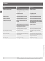
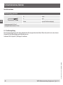
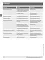
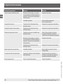
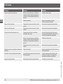
Faults Causes Measures
Signal span drops/too small Diaphragm damaged, e.g. due to impacts,
abrasive/aggressive medium; corrosion at
diaphragm/process connection
Replace instrument
Moisture has entered Fit the cable correctly
Insert the lter element
Signal span varies Operating temperature too high/low Observe the permissible temperatures
Signal span inaccurate Operating temperature too high/low Observe the permissible temperatures
Deviating zero point signal Medium or ambient temperature too
high/low
Operate the instrument within the permis-
sible temperature range; note the permissi-
ble temperature error
Diaphragm damaged, e.g. due to impacts,
abrasive/aggressive medium; corrosion at
diaphragm/process connection
Replace instrument
Operating temperature too high/low Observe the permissible temperatures
Zero point signal too low/high Moisture has entered Fit the cable correctly, insert the lter
element
Too hot case surface Permissible ambient and medium tempe-
rature exceeded
Cool ambient and medium temperature
to the maximum permissible temperature
ranges, at the very least
No output signal No/wrong power supply Rectify the power supply
6. Faults
Seite laden ...
Seite laden ...
Seite laden ...
Seite laden ...
Seite laden ...
Seite laden ...
Seite laden ...
Seite laden ...
Seite laden ...
Seite laden ...
Seite laden ...
Seite laden ...
Seite laden ...
Seite laden ...
Seite laden ...
Seite laden ...
Seite laden ...
Seite laden ...
Seite laden ...
Seite laden ...
Seite laden ...
Seite laden ...
Seite laden ...
Seite laden ...
Seite laden ...
Seite laden ...
Seite laden ...
Seite laden ...
Seite laden ...
Seite laden ...
Seite laden ...
Seite laden ...
Seite laden ...
Seite laden ...
Seite laden ...
Seite laden ...
Seite laden ...
Seite laden ...
Seite laden ...
Seite laden ...
Seite laden ...
Seite laden ...
Seite laden ...
Seite laden ...
Seite laden ...
Seite laden ...
Seite laden ...
Seite laden ...
Seite laden ...
Seite laden ...
Seite laden ...
Seite laden ...
Seite laden ...
Seite laden ...
Seite laden ...
Seite laden ...
Seite laden ...
Seite laden ...
Seite laden ...
Seite laden ...
Seite laden ...
Seite laden ...
Seite laden ...
Seite laden ...
Seite laden ...
Seite laden ...
Seite laden ...
Seite laden ...
Seite laden ...
Seite laden ...
Seite laden ...
Seite laden ...
Seite laden ...
Seite laden ...
Seite laden ...
Seite laden ...
Seite laden ...
Seite laden ...
Seite laden ...
Seite laden ...
-
 1
1
-
 2
2
-
 3
3
-
 4
4
-
 5
5
-
 6
6
-
 7
7
-
 8
8
-
 9
9
-
 10
10
-
 11
11
-
 12
12
-
 13
13
-
 14
14
-
 15
15
-
 16
16
-
 17
17
-
 18
18
-
 19
19
-
 20
20
-
 21
21
-
 22
22
-
 23
23
-
 24
24
-
 25
25
-
 26
26
-
 27
27
-
 28
28
-
 29
29
-
 30
30
-
 31
31
-
 32
32
-
 33
33
-
 34
34
-
 35
35
-
 36
36
-
 37
37
-
 38
38
-
 39
39
-
 40
40
-
 41
41
-
 42
42
-
 43
43
-
 44
44
-
 45
45
-
 46
46
-
 47
47
-
 48
48
-
 49
49
-
 50
50
-
 51
51
-
 52
52
-
 53
53
-
 54
54
-
 55
55
-
 56
56
-
 57
57
-
 58
58
-
 59
59
-
 60
60
-
 61
61
-
 62
62
-
 63
63
-
 64
64
-
 65
65
-
 66
66
-
 67
67
-
 68
68
-
 69
69
-
 70
70
-
 71
71
-
 72
72
-
 73
73
-
 74
74
-
 75
75
-
 76
76
-
 77
77
-
 78
78
-
 79
79
-
 80
80
-
 81
81
-
 82
82
-
 83
83
-
 84
84
-
 85
85
-
 86
86
-
 87
87
-
 88
88
-
 89
89
-
 90
90
-
 91
91
-
 92
92
-
 93
93
-
 94
94
-
 95
95
-
 96
96
-
 97
97
-
 98
98
-
 99
99
-
 100
100


in anderen Sprachen
- français: WIKA IL-10 Mode d'emploi
- español: WIKA IL-10 Instrucciones de operación
Verwandte Papiere
-
WIKA LH-10 Bedienungsanleitung
-
-
-
-
-
-
WIKA UPT-20 tag:model:UPT-21 Bedienungsanleitung
-
-
-
Sonstige Unterlagen
-
IFM PS308A Bedienungsanleitung
-
SICK LFH Level probe Bedienungsanleitung
-
Nice Automation FE, FEP, FI and BF Bedienungsanleitung
-
Baumer CPX Installationsanleitung
-
Grundfos W Series Installation And Operating Instructions Manual
-
 Kessel SG 400 V Mono Original Operation Manual
-
ZIEHL NS6123-6 Schnellstartanleitung
