Pepperl+Fuchs UBE15M-F54-H2-V1 Bedienungsanleitung
- Typ
- Bedienungsanleitung

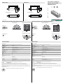
Abmessungen
Elektrischer Anschluss/Kurven/
Zusätzliche Informationen
Electrical Connection / Curves / Additional Information
Dimensions
Technische Daten Technical data
UBE15M-F54-H2-V1
Bohrung und Senkung
für Schrauben/Sechskant M4
22
10
105
94
32
21
25
3.5 3.5
Bore hole and countersinking
for screws/hexagon M4
22
10
105
94
32
21
25
3.5 3.5
Echo
Normsymbol/Anschluss:
Empfänger
Adernfarben gemäß EN 60947-5-2.
1
2
4
3
(BN)
(WH)
(BK)
(BU)
+ UB
nc
- UB
Steckverbinder V1
2
31
4
Richtcharakteristik
Dämpfung (dB)
30°
60°
90°
30°
60°
90°
0°
-10 0-20-30
Charakteristische Ansprechkurve
Abstand X [m]
Versatz Y [m]
Möglicher Abstand (Versatz) der optischen
Achsen von Sender und Empfänger.
15
10
5
010 5 -5 -10
Charakteristische Ansprechkurve
15 m 10 m 5 m 5 m 10 m 15 m
30°
45°
60°
Characteristic response curve
Distance X [m]
Offset Y [m]
Permissible distance (offset) between the optical axis of the
emitter and receiver.
15
10
5
010 5 -5 -10
Characteristic response curve
15 m 10 m 5 m 5 m 10 m 15 m
30°
45°
60°
Direction characteristics
Attenuation (dB)
30°
60°
90°
30°
60°
90°
0°
-10 0-20-30
Echo
Standard symbol/Connection:
Receiver
Core colours in accordance with EN 60947-5-2.
1
2
4
3
(BN)
(WH)
(BK)
(BU)
+ UB
nc
- UB
Connector V1
2
31
4
Partnummer / Part. No.:
Datum / Date:
109086
02/12/2015 DIN A3 -> DIN
45-0182C
Doc. No.:
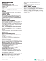
Funktion
Der Empfänger ist Bestandteil eines Komplettsystems aus Empfänger, Sender und Controller
Sender: UBE15M-F54-H1-V1
Controller: UH3-16E4A-K15-R3
Im realen Betrieb werden Sender und Empfänger nicht aufeinander ausgerichtet sein. Dadurch verringert sich die erzielbare Reichweite
Die nebenstehenden Charakteristischen Ansprechkurven zeigen beispielhaft die Reichweite des Systems unter folgenden Betriebsbedingungen.
- Sender und Empfänger sind parallel gegenüberliegend angeordnet. Die Kurve zeigt die Reichweite in Abhängigkeit vom seitlichen
Versatz.
- Der Empfänger ist senkrecht nach unten, der Sender in Richtung des Empfängers angeordnet. Die Kurve zeigt die Reichweite in
Abhängigkeit vom Anstellwinkel.
Hieraus lässt sich die Systemreichweite abhängig von der gegenseitigen Positionierung von Sender und Empfänger für die in der Anwendungspraxis vorkommenden
Bedingungen abschätzen.
Zum Anschluss der Geräte dürfen keine Kabeldosen mit integrierten LEDs verwendet werden!
Allgemeine Daten
Erfassungsbereich 0 ... 15000 mm , Sender - Empfänger aufeinander ausgerichtet
Wandlerfrequenz ca. 40 kHz
Öffnungswinkel ± 45 ° bei -6 dB
Temperaturdrift der Echolaufzeit 0,2 %/K
Elektrische Daten
Betriebsspannung UB10 ... 30 V DC , Welligkeit 10 %SS
Leerlaufstrom I0≤ 15 mA (typ. 10 mA bei UB = 24 V DC)
Ausgang
Ausgangstyp 1 Impulsausgang für Echolaufzeit, open collector npn, kurzschlussfest
0-Pegel (aktiv): UOL ≤ 2 V, IOL ≤ 15 mA
1-Pegel (inaktiv): UOH = UB (pull-up R = 330 kΩ)
Umgebungsbedingungen
Umgebungstemperatur 0 ... 50 °C (32 ... 122 °F)
Lagertemperatur -40 ... 85 °C (-40 ... 185 °F)
Mechanische Daten
Anschlussart Gerätestecker M12 x 1 , 4-polig
Schutzart IP30
Material
Gehäuse PBT
Masse 110 g
Normen- und Richtlinienkonformität
Normenkonformität
Normen EN 60947-5-2:2007
IEC 60947-5-2:2007
Zulassungen und Zertifikate
UL-Zulassung cULus Listed, General Purpose
CSA-Zulassung cCSAus Listed, General Purpose
CCC-Zulassung Produkte, deren max. Betriebsspannung ≤36 V ist, sind nicht zulassungspflichtig und daher nicht mit einer CCC-
Kennzeichnung versehen.
Information
Function
The receiver is part of a complete system consisting of receiver, emitter, and controller
Transmitter UBE15M-F54-H1-V1
Controller: UH3-16E4A-K15-R3
In real mode, the transmitter and receiver will not be not aligned to each other. This reduces the detection range that can be achieved.
The characteristic response curve to the side illustrates examples of the detection range of the system under the following operating conditions.
- The transmitter and receiver are arranged so they lie parallel opposite each other. The graph shows the detection range as a function
of lateral offset.
- The receiver is arranged vertically downward, while the emitter is arranged in the direction of the receiver. The graph shows the detection
range as a function of the angle of incidence.
This makes it possible to evaluate the detection range of the system as a function of the positioning of the transmitter and receiver for conditions that will occur in
practical usage.
Cable sockets with built-in indicator LEDs must not be used to connect this device!
General specifications
Sensing range 0 ... 15000 mm , emitter - receiver synchronised
Transducer frequency approx. 40 kHz
Angle of divergence ± 45 ° at -6 dB
Temperature drift of echo propagation delay 0.2 %/K
Electrical specifications
Operating voltage UB10 ... 30 V DC , ripple 10 %SS
No-load supply current I0≤ 15 mA (typ. 10 mA at UB = 24 V DC)
Output
Output type 1 pulse output for echo run time, open collector NPN, short-circuit proof
0 level (active): UOL ≤ 2 V, IOL ≤ 15 mA
1 level (inactive): UOH = UB (pull-up R = 330 kOhm)
Ambient conditions
Ambient temperature 0 ... 50 °C (32 ... 122 °F)
Storage temperature -40 ... 85 °C (-40 ... 185 °F)
Mechanical specifications
Connection type Connector M12 x 1 , 4-pin
Degree of protection IP30
Material
Housing PBT
Mass 110 g
Compliance with standards and directives
Standard conformity
Standards EN 60947-5-2:2007
IEC 60947-5-2:2007
Approvals and certificates
UL approval cULus Listed, General Purpose
CSA approval cCSAus Listed, General Purpose
CCC approval CCC approval / marking not required for products rated ≤36 V
Information
Ultraschallsensor, Empfänger
Ultrasonic sensor, receiver
Alle Abmessungen in mm All dimensions im mm

Adressen / Addresses / Adresses / Direcciónes / Indirizzi
Contact Pepperl+Fuchs GmbH · 68301 Mannheim · Germany · Tel. +49 621 776-4411 · Fax +49 621 776-27-4411 · E-mail: fa-info@de.pepperl-fuchs.com
Worldwide Headquarters: Pepperl+Fuchs GmbH · Mannheim · Germany · E-mail: [email protected]l-fuchs.com
USA Headquarters: Pepperl+Fuchs Inc. · Twinsburg · USA · E-mail: fa-in[email protected].com
Asia Pacific Headquarters: Pepperl+Fuchs Pte Ltd · Singapore · E-mail: [email protected]perl-fuchs.com · Company Registration No. 199003130E
For more contact-adresses refer to the catalogue or internet: http://www.pepperl-fuchs.com
-
 1
1
-
 2
2


Pepperl+Fuchs UBE15M-F54-H2-V1 Bedienungsanleitung
- Typ
- Bedienungsanleitung
in anderen Sprachen
Verwandte Papiere
-
Pepperl+Fuchs UBE15M-F54-H1-V1 Bedienungsanleitung
-
-
-
-
-
-
-
-
-
Sonstige Unterlagen
-
Ecom Smart-Ex 02 DZ2 Safety Manual
-
BBC Bircher LBGate Benutzerhandbuch
-
-
-
 Vega Profibus PA/DP segment coupler Bedienungsanleitung
-
CARLO GAVAZZI MPF3-912RSLA Benutzerhandbuch
-
CARLO GAVAZZI PD98CNT30QMU Benutzerhandbuch
-
-
