Pepperl+Fuchs UB2000-30GM-H3-V1 Bedienungsanleitung
- Typ
- Bedienungsanleitung

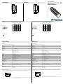
Abmessungen
Elektrischer Anschluss/Kurven/
Zusätzliche Informationen
Electrical Connection / Curves / Additional Information
Dimensions
Technische Daten Technical data
UB2000-30GM-H3-V1
M30 x 1,5
90
80
60
M12 x 1
M30 x 1.5
90
80
60
M12 x 1
Ta k t
Echo
Normsymbol/Anschluss:
2 = Eingang für Sendeimpuls
4 = Ausgang für Echolaufzeit
Adernfarben gemäß EN 60947-5-2.
1
2
3
4
(BN)
(WH)
(BU)
(BK)
+ UB
- UB
U
Steckverbinder V1
2
31
4
Charakteristische Ansprechkurve
Abstand X [m]
Kurve 1: ebene Platte 100 mm x 100 mm
Kurve 2: Rundstab, Ø 25 mm
Abstand Y [m]
0 0,5 1 1,5 2 2,5 3 3,5
1,5
1
0,5
0
-0,5
-1
-1,5
1
2
Characteristic response curves
Distance X [m]
Curve 1: flat surface 100 mm x 100 mm
Curve 2: round bar, Ø 25 mm
Distance Y [m]
0 0.5 1 1.5 2 2.5 3 3.5
1.5
1
0.5
0
-0.5
-1
-1.5
1
2
Clock
Echo
Standard symbol/Connection:
2 = Emitter pulse input
4 = Echo propagation time output
Core colours in accordance with EN 60947-5-2.
1
2
3
4
(BN)
(WH)
(BU)
(BK)
+ UB
- UB
U
Connector V1
2
31
4
Part. No.:
Date:
130473
12/14/2010 DIN A3 -> DIN
45-1222B
Doc. No.:
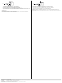
Funktion
Die Ermittlung des Objektabstands erfolgt in einer nachgeschalteten Auswerteelektronik wie z. B. einem SPS-Modul oder einer eigenen
vorhandene Auswerteeinheit.
Der Objektabstand wird im Puls-Echobetrieb aus der Schalllaufzeit ∆t ermittelt. Der Sendeimpuls des Ultraschall-Sensors startet mit der
fallenden Signalflanke am Takteingang des Sensors.
Wir empfehlen, den Takteingang des Sensors mittels eines npn-Transistors anzusteuern, der den Takteingang auf das Potenzial -UB legt.
Der Takteingang des Sensors ist intern über einen Pull-Up-Widerstand mit +UB verbunden.
Allgemeine Daten
Erfassungsbereich 80 ... 2000 mm
Einstellbereich 120 ... 2000 mm
Blindzone 0 ... 80 mm 1)
Normmessplatte 100 mm x 100 mm
Wandlerfrequenz ca. 180 kHz
Elektrische Daten
Betriebsspannung UB10 ... 30 V DC , Welligkeit 10 %SS
Leerlaufstrom I0≤ 30 mA
Eingang
Eingangstyp 1 Impulseingang für Sendeimpuls (Takt)
0-Pegel (aktiv): < 5 V (UB > 15 V)
1-Pegel (inaktiv): > 10 V ... +UB (UB > 15 V)
0-Pegel (aktiv): < 1/3 UB (10 V < UB < 15 V)
1-Pegel (inaktiv): > 2/3 UB ... +UB (10 V < UB < 15 V)
Impulsdauer 20 ... 300 µs (typ. 200 µs) 2)
Pausendauer ≥ 50 x Impulsdauer
Impedanz 10 kOhm intern mit +UB verbunden
Ausgang
Ausgangstyp 1 Impulsausgang für Echolaufzeit, kurzschlussfest
Open Collector pnp mit pull down Widerstand = 22 kΩ
0-Pegel (kein Echo): -UB
1-Pegel (Echo erkannt): ≥ (+UB-2 V)
Bemessungsbetriebsstrom Ie15 mA , kurzschluss-/überlastfest
Temperatureinfluss der Echolaufzeit: 0,17 % /K
Umgebungsbedingungen
Umgebungstemperatur -25 ... 85 °C (-13 ... 185 °F)
Lagertemperatur -40 ... 85 °C (-40 ... 185 °F)
Mechanische Daten
Anschlussart Gerätestecker M12 x 1 , 4-polig
Schutzart IP67
Material
Gehäuse Messing, vernickelt, Kunststoffteile PBT
Wandler Epoxidharz/Glashohlkugelgemisch; Schaum Polyurethan
Masse 140 g
Normen- und Richtlinienkonformität
Normenkonformität
Normen EN 60947-5-2:2007
IEC 60947-5-2:2007
Takt
Echo
T
i
∆ t
t
t
Function
The sensing range is determined in the downstream evaluation electronics such as PLC modules or other existing evaluation units.
The object distance in pulse-echo mode is obtained from the echo time ∆t. The emission of an ultrasonic pulse starts simultaneously with
the falling slope of the clock input signal.
We recommend the usage of a npn-transistor to trigger the sensors clock input. The sensors clock input is connected to the +UB potential
internally by means of a pull up resistor.
General specifications
Sensing range 80 ... 2000 mm
Adjustment range 120 ... 2000 mm
Unusable area 0 ... 80 mm 1)
Standard target plate 100 mm x 100 mm
Transducer frequency approx. 180 kHz
Electrical specifications
Operating voltage UB10 ... 30 V DC , ripple 10 %SS
No-load supply current I0≤ 30 mA
Input
Input type 1 pulse input for transmitter pulse (clock)
0-level (active): < 5 V (UB > 15 V)
1-level (inactive): > 10 V ... +UB (UB > 15 V)
0-level (active): < 1/3 UB (10 V < UB < 15 V)
1-level (inactive): > 2/3 UB ... +UB (10 V < UB < 15 V)
Pulse length 20 ... 300 µs (typ. 200 µs) 2)
Pause length ≥ 50 x pulse length
Impedance 10 kOhm internal connected to +UB
Output
Output type 1 pulse output for echo run time, short-circuit proof
open collector PNP with pulldown resistor = 22 kOhm
level 0 (no echo): -UB
level 1 (echo detected): ≥ (+UB-2 V)
Rated operational current Ie15 mA , short-circuit/overload protected
Temperature influence the echo propagation time: 0.17 % / K
Ambient conditions
Ambient temperature -25 ... 85 °C (-13 ... 185 °F)
Storage temperature -40 ... 85 °C (-40 ... 185 °F)
Mechanical specifications
Connection type Device connector M12 x 1 , 4-pin
Protection degree IP67
Material
Housing nickel plated brass; plastic components: PBT
Transducer epoxy resin/hollow glass sphere mixture; polyurethane foam
Mass 140 g
Compliance with standards and directives
Standard conformity
Standards EN 60947-5-2:2007
IEC 60947-5-2:2007
Clock
Echo
T
i
∆ t
t
t
Ultraschallsensor
Ultrasonic sensor

Adressen / Addresses / Adresses / Direcciónes / Indirizzi
Contact Pepperl+Fuchs GmbH · 68301 Mannheim · Germany · Tel. +49 621 776-4411 · Fax +49 621 776-27-4411 · E-mail: [email protected]l-fuchs.com
Worldwide Headquarters: Pepperl+Fuchs GmbH · Mannheim · Germany · E-mail: info@de.pepperl-fuchs.com
USA Headquarters: Pepperl+Fuchs Inc. · Twinsburg · USA · E-mail: fa-info@us.pepperl-fuchs.com
Asia Pacific Headquarters: Pepperl+Fuchs Pte Ltd · Singapore · E-mail: [email protected]perl-fuchs.com · Company Registration No. 199003130E
For more contact-adresses refer to the catalogue or internet: http://www.pepperl-fuchs.com
1) Die Blindzone BR ist abhängig von der Impulsdauer Ti .
Bei kürzerer Impulsdauer ist auch der Blindbereich kleiner.
2) Die Reichweite des Sensors ist abhängig von der Impulsdauer Ti .
Bei einer Impulsdauer < als der typischen Impulsdauer ist mit reduzierter Reichweite zu rech-
nen.
Einbaubedingungen
Bei einem Einbau des Sensors an Orten, an denen die Betriebstemperatur unter 0 °C sinken kann, müssen zur Montage die
Befestigungsflansche BF30, BF30-F oder BF 5-30 verwendet werden.
Takt
Echo
Ta k t
+ U
B
- U
B
1) The unusable area (blind range) BR depends on the pulse duration Ti .
The unusable area reaches a minimum with the shortest pulse duration.
2) The sensors detection range depends on the pulse duration Ti.
With pulse duration < typical pulse duration, the sensors detection range may be reduced.
Mounting conditions
If the sensor is installed in places where the operating temperature can fall below 0 °C, the BF30, BF30-F or BF 5-30 fixing clamp must be
used.
Clock
Echo
Clock
+ U
B
- U
B
-
 1
1
-
 2
2


Pepperl+Fuchs UB2000-30GM-H3-V1 Bedienungsanleitung
- Typ
- Bedienungsanleitung
in anderen Sprachen
Verwandte Artikel
-
Pepperl+Fuchs UB2000-30GM-H3 Bedienungsanleitung
-
-
-
-
-
-
-
-
-