Pepperl+Fuchs UB1000-18GM75-I-V15 Bedienungsanleitung
- Typ
- Bedienungsanleitung

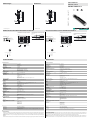
Abmessungen
Elektrischer Anschluss/Kurven/
Zusätzliche Informationen
Electrical Connection / Curves / Additional Information
Dimensions
Technische Daten Technical data
UB1000-18GM75-I-V15
48
75
85
M12 x 1
M18 x 1
4
24
LEDs
48
75
85
M12 x 1
M18 x 1
4
24
LEDs
Normsymbol/Anschluss:
(Version I)
Lerneingang
Sync.
Analogausgang
Adernfarben gemäß EN 60947-5-2.
1
2
4
3
5
+ UB
- UB
(BN)
(WH)
(GY)
(BK)
(BU)
U
1
3
4
5
2
0 200 400 600 800 1000 1200 1400 1600
250
200
150
100
5
0
-50
-100
-150
-200
-250
X
Y
Abstand X [mm]
Charakteristische Ansprechkurve
Abstand Y [mm]
ebene Platte 100 mm x 100 mm
Rundstab Ø 25 mm
breite Schallkeule
schmale Schallkeule
Programmierung der Auswertegrenzen
Steigende Rampe
A1 < A2:
Fallende Rampe
A2 < A1:
Objektabstand
A1 A2
A2 A1
Programmed analogue output function
Rising ramp
A1 < A2:
Falling ramp
A2 < A1:
object range
A1 A2
A2 A1
0 200 400 600 800 1000 1200 1400 1600
250
200
150
100
5
0
-50
-100
-150
-200
-250
X
Y
Characteristic response curve
Distance X [mm]
Distance Y [mm]
flat surface 100 mm x 100 mm
round bar, Ø 25 mm
wide sound lobe
narrow sound lobe
Standard symbol/Connections:
(version I)
Teaching input
Sync.
Analog output
Core colours in accordance with EN 60947-5-2.
1
2
4
3
5
+ UB
- UB
(BN)
(WH)
(GY)
(BK)
(BU)
U
1
3
4
5
2
Partnummer / Part. No.:
Datum / Date:
204535
04/01/2015 DIN A3 -> DIN
45-2304B
Doc. No.:
1 BN
2 WH
3 BU
4 BK
5 GY
Wire colors in accordance with EN 60947-5-2
(brown)
(white)
(blue)
(black)
(gray)
1 BN
2 WH
3 BU
4 BK
5 GY
Adernfarben gemäß EN 60947-5-2
(braun)
(weiß)
(blau)
(schwarz)
(grau)
Beschreibung der Sensorfunktionen
Programmierung
Der Sensor ist mit einem programmierbaren Analogausgang mit zwei programmierbaren Auswertegrenzen ausgestattet. Das Programmieren der
Auswertegrenzen und der Betriebsart wird durch Anlegen der Spannung -UB oder +UB an den Lerneingang vorgenommen. Die Versorgungsspan-
nung muss mindestens 1 s lang am Lerneingang anliegen. LEDs zeigen an, ob der Sensor das Zielobjekt während des Programmiervorgangs
erkennt.
Hinweis:
Ein Einlernen der Auswertegrenzen ist nur unmittelbar nach dem Zuschalten der Spannungsversorgung möglich. Ein Zeitschloss sichert 5 Minuten
Allgemeine Daten
Erfassungsbereich 70 ... 1000 mm
Einstellbereich 90 ... 1000 mm
Blindzone 0 ... 70 mm
Normmessplatte 100 mm x 100 mm
Wandlerfrequenz ca. 255 kHz
Ansprechverzug ca. 125 ms
Anzeigen/Bedienelemente
LED gelb permanent gelb: Objekt im Auswertebereich
gelb blinkend: Lernfunktion, Objekt erkannt
LED rot permanent rot: Störung
rot blinkend: Lernfunktion, Objekt nicht erkannt
Elektrische Daten
Betriebsspannung UB10 ... 30 V DC , Welligkeit 10 %SS
Leerlaufstrom I0≤ 45 mA
Eingang/Ausgang
Synchronisation 1 Synchronanschluss, bidirektional
0-Pegel: -UB...+1 V
1-Pegel: +4 V...+UB
Eingangsimpedanz: > 12 KΩ
Synchronisationsimpuls: ≥ 100 µs, Synchronisationsimpulspause: ≥ 2 ms
Synchronisationsfrequenz
Gleichtaktbetrieb ≤ 40 Hz
Multiplexbetrieb ≤ 40 Hz / n, n = Anzahl der Sensoren
Eingang
Eingangstyp 1 Lerneingang
untere Auswertegrenze A1: -UB ... +1 V, obere Auswertegrenze A2: +4 V ... +UB
Eingangsimpedanz: > 4,7 kΩ, Lernimpuls: ≥ 1 s
Ausgang
Ausgangstyp 1 Analogausgang 4 ... 20 mA
Auflösung 0,35 mm
Kennlinienabweichung ± 1 % vom Endwert
Reproduzierbarkeit ± 0,1 % vom Endwert
Lastimpedanz 0 ... 300 Ω
Temperatureinfluss ± 1,5 % vom Endwert
Umgebungsbedingungen
Umgebungstemperatur -25 ... 70 °C (-13 ... 158 °F)
Lagertemperatur -40 ... 85 °C (-40 ... 185 °F)
Mechanische Daten
Anschlussart Gerätestecker M12 x 1 , 5-polig
Schutzart IP67
Material
Gehäuse Messing, vernickelt
Wandler Epoxidharz/Glashohlkugelgemisch; Schaum Polyurethan, Deckel PBT
Masse 60 g
Werkseinstellungen
Ausgang Auswertegrenze A1: 90 mm
Auswertegrenze A2: 1000 mm
Ausgangsfunktion: steigende Rampe
Schallkeule breit
Normen- und Richtlinienkonformität
Normenkonformität
Normen EN 60947-5-2:2007
IEC 60947-5-2:2007
EN 60947-5-7:2003
IEC 60947-5-7:2003
Zulassungen und Zertifikate
UL-Zulassung cULus Listed, General Purpose
CSA-Zulassung cCSAus Listed, General Purpose
CCC-Zulassung Produkte, deren max. Betriebsspannung ≤36 V ist, sind nicht zulassungspflichtig und daher nicht mit einer CCC-
Kennzeichnung versehen.
Description of Sensor Functions
Programming procedure
The sensor features a programmable analog output with two programmable evaluation boundaries. Programming the evaluation boundaries and
the operating mode is done by applying the supply voltage -UB or +UB to the Teach-In input. The supply voltage must be applied to the Teach-In
input for at least 1 s. LEDs indicate whether the sensor has recognized the target during the programming procedure.
Note:
Evaluation boundaries may only be specified directly after Power on. A time lock secures the adjusted switching points against unintended mod-
ification 5 minutes after Power on. To modify the evaluation boundaries later, the user may specify the desired values only after a new Power On.
General specifications
Sensing range 70 ... 1000 mm
Adjustment range 90 ... 1000 mm
Unusable area 0 ... 70 mm
Standard target plate 100 mm x 100 mm
Transducer frequency approx. 255 kHz
Response delay approx. 125 ms
Indicators/operating means
LED yellow solid yellow: object in the evaluation range
yellow, flashing: program function, object detected
LED red solid red: Error
red, flashing: program function, object not detected
Electrical specifications
Operating voltage UB10 ... 30 V DC , ripple 10 %SS
No-load supply current I0≤ 45 mA
Input/Output
Synchronization 1 synchronous connection, bi-directional
0-level: -UB...+1 V
1-level: +4 V...+UB
input impedance: > 12 kΩ
synchronization pulse: ≥ 100 µs, synchronization interpulse period: ≥ 2 ms
Synchronization frequency
Common mode operation ≤ 40 Hz
Multiplex operation ≤ 40 Hz /n, n = number of sensors
Input
Input type 1 program input
lower evaluation limit A1: -UB ... +1 V, upper evaluation limit A2: +4 V ... +UB
input impedance: > 4.7 kΩ, pulse duration: ≥ 1 s
Output
Output type 1 analog output 4 ... 20 mA
Resolution 0.35 mm
Deviation of the characteristic curve ± 1 % of full-scale value
Repeat accuracy ± 0.1 % of full-scale value
Load impedance 0 ... 300 Ohm
Temperature influence ± 1.5 % of full-scale value
Ambient conditions
Ambient temperature -25 ... 70 °C (-13 ... 158 °F)
Storage temperature -40 ... 85 °C (-40 ... 185 °F)
Mechanical specifications
Connection type Connector M12 x 1 , 5-pin
Degree of protection IP67
Material
Housing brass, nickel-plated
Transducer epoxy resin/hollow glass sphere mixture; foam polyurethane, cover PBT
Mass 60 g
Factory settings
Output evaluation limit A1: 90 mm
evaluation limit A2: 1000 mm
output function: rising slope
Beam width wide
Compliance with standards and directives
Standard conformity
Standards EN 60947-5-2:2007
IEC 60947-5-2:2007
EN 60947-5-7:2003
IEC 60947-5-7:2003
Approvals and certificates
UL approval cULus Listed, General Purpose
CSA approval cCSAus Listed, General Purpose
CCC approval CCC approval / marking not required for products rated ≤36 V
Ultraschallsensor
Ultrasonic sensor
Alle Abmessungen in mm All dimensions im mm

Adressen / Addresses / Adresses / Direcciónes / Indirizzi
Contact Pepperl+Fuchs GmbH · 68301 Mannheim · Germany · Tel. +49 621 776-4411 · Fax +49 621 776-27-4411 · E-mail: [email protected]l-fuchs.com
Worldwide Headquarters: Pepperl+Fuchs GmbH · Mannheim · Germany · E-mail: info@de.pepperl-fuchs.com
USA Headquarters: Pepperl+Fuchs Inc. · Twinsburg · USA · E-mail: fa-in[email protected]om
Asia Pacific Headquarters: Pepperl+Fuchs Pte Ltd · Singapore · E-mail: [email protected]perl-fuchs.com · Company Registration No. 199003130E
For more contact-adresses refer to the catalogue or internet: http://www.pepperl-fuchs.com
nach dem letzten Einlernen die eingestellten Werte gegen ungewolltes Verändern. Sollen die Auswertegrenzen zu einem späteren Zeitpunkt
verändert werden, so ist dies erst nach einem erneuten Power On möglich.
Hinweis:
Wenn ein Programmieradapter UB-PROG2 zur Programmierung verwendet wird, steht die Taste A1 für -UB und die Taste A2 für +UB.
Programmierung des Analogausgangs
Steigende Rampe
1. Positionieren Sie das Zielobjekt am nahen Ende des gewünschten Auswertebereichs
2. Programmieren Sie die Auswertegrenze durch Anlegen von -UB an den Lerneingang (gelbe LED blinkt)
3. Zum Speichern der Auswertegrenze trennen Sie den Lerneingang von -UB
4. Positionieren Sie das Zielobjekt am fernen Ende des gewünschten Auswertebereichs
5. Programmieren Sie die Auswertegrenze durch Anlegen von +UB an den Lerneingang (gelbe LED blinkt)
6. Zum Speichern der Auswertegrenze trennen Sie den Lerneingang von +UB
Fallende Rampe
1. Positionieren Sie das Zielobjekt am fernen Ende des gewünschten Auswertebereichs
2. Programmieren Sie die Auswertegrenze durch Anlegen von -UB an den Lerneingang (gelbe LED blinkt)
3. Zum Speichern der Auswertegrenze trennen Sie den Lerneingang von -UB
4. Positionieren Sie das Zielobjekt am nahen Ende des gewünschten Auswertebereichs
5. Programmieren Sie die Auswertegrenze durch Anlegen von +UB an den Lerneingang (gelbe LED blinkt)
6. Zum Speichern der Auswertegrenze trennen Sie den Lerneingang von +UB
Einstellen der Ultraschallkeulen-Charakteristik:
Der Ultraschall-Sensor bietet 2 verschiedene Schallkeulenformen.
1. Schmale Ultraschallkeule
• Spannungsversorgung abschalten
• Lerneingang mit -UB verbinden
• Spannungsversorgung zuschalten
• die rote LED blinkt einfach, gefolgt von einer Pause
• gelbe LED: permanent ein: signalisiert Objekt/Störobjekt im Erfas-
sungsbereich vorhanden
• Lerneingang von -UB trennen
2. Breite Ultraschallkeule
• Spannungsversorgung abschalten
• Lerneingang mit +UB verbinden
• Spannungsversorgung zuschalten
• die rote LED blinkt doppelt, gefolgt von einer Pause
• gelbe LED: permanent ein: signalisiert Objekt/Störobjekt im Erfas-
sungsbereich vorhanden
• Lerneingang von +UB trennen
Werkseinstellung
Siehe Technische Daten
Anzeigen
Der Sensor ist mit LEDs zur Anzeige der Betriebszustände ausgestattet.
Synchronisation
Der Sensor ist mit einem Synchronisationseingang zur Unterdrückung gegenseitiger Beeinflussung durch fremde Ultraschallsignale ausgestattet.
Wenn dieser Eingang unbeschaltet ist, arbeitet der Sensor mit intern generierten Taktimpulsen. Er kann durch Anlegen externer Recheckimpulse
synchronisiert werden. Die Pulsdauer muss ≥ 100 µs betragen. Jede fallende Impulsflanke triggert das Senden eines einzelnen Ultraschallimpuls-
es. Wenn das Signal am Synchronisationseingang ≥ 1 Sekunde Low-Pegel führt, geht der Sensor in die normale, unsynchronisierte Betriebsart
zurück. Dies ist auch der Fall, wenn der Synchronisationseingang von externen Signalen abgetrennt wird (siehe Hinweis unten).
Liegt am Synchronisationseingang ein High-Pegel > 1 Sekunde an, geht der Sensor in den Standby. In dieser Betriebsart bleiben die zuletzt ein-
genommenen Ausgangszustände erhalten.
Hinweis:
Wird die Möglichkeit der Synchronisation nicht genutzt, muss der Synchronisationseingang mit Massepotential (0 V) verbunden werden oder der
Sensor muss mit einer 4-poligen V1-Kabeldose betrieben werden.
Die Möglichkeit zur Synchronisation steht während des Programmiervorgangs nicht zur Verfügung und umgekehrt kann während der Synchroni-
sation der Sensor nicht programmiert werden.
Folgende Synchronisationsarten sind möglich:
1. Mehrere Sensoren (max. Anzahl siehe Technische Daten) können durch einfaches Verbinden ihrer Synchronisationseingänge synchro-
nisiert werden. In diesem Fall arbeiten die Sensoren selbstsynchronisiert nacheinander im Multiplex-Betrieb. Zu jeder Zeit sendet immer
nur ein Sensor (siehe Hinweis unten).
2. Mehrere Sensoren können gemeinsam von einem externen Signal angesteuert werden. In diesem Fall werden die Sensoren parallel ge-
triggert und arbeiten zeitsynchron, d. h. gleichzeitig.
3. Mehrere Sensoren werden zeitversetzt durch ein externes Signal angesteuert. In diesem Fall arbeitet jederzeit immer nur ein Sensor extern
synchronisiert (siehe Hinweis unten).
4. Ein High-Pegel (+UB) am Synchronisationseingang versetzt den Sensor in den Standby.
Hinweis:
Die Ansprechzeit der Sensoren erhöht sich proportional zur Anzahl an Sensoren in der Synchronisationskette. Durch das Multiplexen laufen die
Messzyklen der einzelnen Sensoren zeitlich nacheinander ab.
Einbaubedingungen
Bei einem Einbau des Sensors an Orten, an denen die Betriebstemperatur unter 0 °C sinken kann, müssen zur Montage die Befestigungsflansche
BF18, BF18-F oder BF 5-30 verwendet werden.
Soll der Sensor direkt in einer Durchgangsbohrung montiert werden, so ist unter Verwendung der beiliegenden Stahlmuttern die Befestigung in
der Mitte der Sensorhülse vorzunehmen. Für eine Verschraubung im vorderen Bereich der Gewindehülse sind die als Zubehör erhältlichen Kunst-
stoffmuttern mit Zentrierring zu verwenden.
rote LED gelbe LED
Im normalen Betrieb
störungsfreier Betrieb
Objekt im Auswertebereich
kein Objekt im Auswertebereich
Störung (z. B. Druckluft)
aus
aus
ein
ein
aus
letzter gültiger Zustand
Während der Programmierung
Objekt erkannt
kein Objekt erkannt
Objekt unsicher (Programmierung ungültig)
aus
blinkend
ein
blinkend
aus
aus
Pause
Pause
Note:
If a programming adapter UB-PROG2 is used for the programming procedure, button A1 is assigned to -UB and button A2 is assigned to +UB.
Programming the analog output
Rising ramp
1. Place the target at the near end of the desired evaluation range
2. Program the evaluation boundary by applying -UB to the Teach-In input (yellow LED flashes)
3. Disconnect the Teach-In input from -UB to save the evaluation boundary
4. Place the target at the far end of the desired evaluation range
5. Program the evaluation boundary by applying +UB to the Teach-In input (yellow LED flashes)
6. Disconnect the Teach-In input from +UB to save the evaluation boundary
Falling ramp
1. Place the target at the far end of the desired evaluation range
2. Program the evaluation boundary by applying -UB to the Teach-In input (yellow LED flashes)
3. Disconnect the Teach-In input from -UB to save the evaluation boundary
4. Place the target at the near end of the desired evaluation range
5. Program the evaluation boundary by applying +UB to the Teach-In input (yellow LED flashes)
6. Disconnect the Teach-In input from +UB to save the evaluation boundary
Adjusting the sound cone characteristics:
The ultrasonic sensor enables two different shapes of the sound cone, a wide angle sound cone and a small angle sound cone.
1. Small angle sound cone
• switch off the power supply
• connect the Teach-In input wire to -UB
• switch on the power supply
• the red LED flashes once with a pause before the next.
• yellow LED: permanently on: indicates the presence of an object or
disturbing object within the sensing range
• disconnect the Teach-In input wire from -UB and the changing is saved
2. Wide angle sound cone
• switch off the power supply
• connect the Teach-In input wire with +UB
• switch on the power supply
• the red LED double-flashes with a long pause before the next.
• yellow LED: permanently on: indicates an object or disturbing object
within the sensing range
• disconnect the Teach-In input wire from +UB and the changing is saved
Factory settings
See technical data.
Display
The sensor provides LEDs to indicate various conditions.
Synchronization
This sensor features a synchronization input for suppressing ultrasonic mutual interference ("cross talk"). If this input is not connected, the sensor will
operate using internally generated clock pulses. It can be synchronized by applying an external square wave. The pulse duration must be ≥ 100 µs.
Each falling edge of the synchronization pulse triggers transmission of a single ultrasonic pulse. If the synchronization signal remains low for ≥ 1 sec-
ond, the sensor will revert to normal operating mode. Normal operating mode can also be activated by opening the signal connection to the synchro-
nization input (see note below).
If the synchronization input goes to a high level for > 1 second, the sensor will switch to standby mode. In this mode, the outputs will remain in the last
valid output state.
Note:
If the option for synchronization is not used, the synchronization input has to be connected to ground (0 V) or the sensor must be operated via a V1
cordset (4-pin).
The synchronization function cannot be activated during programming mode and vice versa.
The following synchronization modes are possible:
1. Several sensors (max. number see technical data) can be synchronized together by interconnecting their respective synchronization inputs. In
this case, each sensor alternately transmits ultrasonic pulses in a self multiplexing mode. No two sensors will transmit pulses at the same time
(see note below).
2. Multiple sensors can be controlled by the same external synchronization signal. In this mode the sensors are triggered in parallel and are syn-
chronized by a common external synchronization pulse.
3. A separate synchronization pulse can be sent to each individual sensor. In this mode the sensors operate in external multiplex mode (see note
below).
4. A high level (+UB) on the synchronization input switches the sensor to standby mode.
Note:
Sensor response times will increase proportionally to the number of sensors that are in the synchronization string. This is a result of the multiplexing of
the ultrasonic transmit and receive signal and the resulting increase in the measurement cycle time.
Installation conditions
If the sensor is installed at places, where the environment temperature can fall below 0 °C, for the sensors fixation, one of the mounting flanges BF18,
BF18-F or BF 5-30 must be used.
In case of direct mounting of the sensor in a through hole using the steel nuts, it has to be fixed at the middle of the housing thread. If a fixation at the
front end of the threaded housing is required, plastic nuts with centering ring (accessories) must be used.
Red LED Yellow LED
During Normal operation
Proper operation
Object in evaluation range
No object in evaluation range
Interference (e.g. compressed air)
Off
Off
On
On
Off
Remains in previous state
During sensor programming
Object detected
No object detected
Object uncertain (programming invalid)
Off
Flashes
On
Flashes
Off
Off
pause
pause
-
 1
1
-
 2
2


Pepperl+Fuchs UB1000-18GM75-I-V15 Bedienungsanleitung
- Typ
- Bedienungsanleitung
in anderen Sprachen
Verwandte Artikel
-
Pepperl+Fuchs UB500-18GM75-I-V15 Bedienungsanleitung
-
-
-
-
-
-
-
-
-