Pepperl+Fuchs UB2000-F54-I-V15 Bedienungsanleitung
- Typ
- Bedienungsanleitung

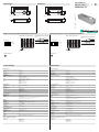
Abmessungen
Elektrischer Anschluss/Kurven/
Zusätzliche Informationen
Electrical Connection / Curves / Additional Information
Dimensions
Technische Daten
Technical data
UB2000-F54-I-V15
Bohrung und Senkung
für Schrauben/Sechskant M4
3,5 3,5
120
25
105
94
32
21
Bore hole and countersinking
for screws/hexagon M4
3.5 3.5
120
25
105
94
32
21
Normsymbol/Anschluss:
(Version I)
Lerneingang
Synchron
Analogausgang
Adernfarben gemäß EN 60947-5-2.
1
2
4
3
5
(BN)
(WH)
(BK)
(BU)
(GY)
+ UB
- UB
U
Steckverbinder V15
2
31
45
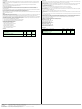
Abstand X [m]
Charakteristische Ansprechkurve
Abstand Y [m]
Kurve 1: ebene Platte 100 mm x 100 mm
Kurve 2: Rundstab, Ø 25 mm
0,5
0,4
0,3
0,2
0,1
0,0
-0,1
-0,2
-0,3
-0,4
-0,5
0 0,5 1 1,5 2 2,5 3 3,5
1
2
X
Y
Programmierung der Auswertegrenzen
Steigende Rampe
A1 < A2:
Fallende Rampe
A2 < A1:
Objektabstand
A1 A2
A2 A1
Programmed analogue output function
Rising ramp
A1 < A2:
Falling ramp
A2 < A1:
object range
A1 A2
A2 A1
Characteristic response curve
Distance X [m]
Distance Y [m]
Curve 1: flat surface 100 mm x 100 mm
Curve 2: round bar, Ø 25 mm
0.5
0.4
0.3
0.2
0.1
0.0
-0.1
-0.2
-0.3
-0.4
-0.5
0 0.5 1 1.5 2 2.5 3 3.5
1
2
X
Y
Standard symbol/Connections:
(version I)
Teaching input
Synchronous
Analog output
Core colours in accordance with EN 60947-5-2.
1
2
4
3
5
(BN)
(WH)
(BK)
(BU)
(GY)
+ UB
- UB
U
Connector V15
2
31
45
Part. No.:
Date:
108162
12/15/2010 DIN A3 -> DIN
45-0126B
Doc. No.:
Allgemeine Daten
Erfassungsbereich 80 ... 2000 mm
Einstellbereich 100 ... 2000 mm
Blindzone 0 ... 80 mm
Normmessplatte 100 mm x 100 mm
Wandlerfrequenz ca. 175 kHz
Ansprechverzug 150 ms
Anzeigen/Bedienelemente
LED grün permanent grün: Betriebsanzeige
grün blinkend: Lernfunktion
LED gelb permanent gelb: Objekt im Auswertebereich
gelb blinkend: Lernfunktion, Objekt erkannt
LED rot blinkend:
Normalbetrieb: Störung
Lernfunktion: Objekt nicht erkannt
permanent:
Lernfunktion, Objekt unsicher
Elektrische Daten
Betriebsspannung UB10 ... 30 V DC , Welligkeit 10 %SS
Leerlaufstrom I0 55 mA
Eingang/Ausgang
Synchronisation 1 Synchroneingang
0-Pegel: -UB...+1 V
1-Pegel: +4 V...+UB
Eingangsimpedanz: > 12 k
Synchronisationsimpuls: 0,1 ... 28 ms
Synchronisationsfrequenz
Gleichtaktbetrieb 33 Hz
Multiplexbetrieb 33 / n Hz, n = Anzahl der Sensoren
Eingang
Eingangstyp 1 Lerneingang
untere Auswertegrenze A1: -UB ... +1 V, obere Auswertegrenze A2: +4 V ... +UB
Eingangsimpedanz: > 4,7 k, Lernimpuls: 1 s
Ausgang
Ausgangstyp 1 Analogausgang 4 ... 20 mA
Voreinstellung Auswertegrenze A1: 100 mm Auswertegrenze A2: 2000 mm
Auflösung 0,5 mm
Kennlinienabweichung ± 1 % vom Endwert
Reproduzierbarkeit ± 0,1 % vom Endwert
Lastimpedanz 0 ... 300
Temperatureinfluss ± 1,5 % vom Endwert
Umgebungsbedingungen
Umgebungstemperatur -25 ... 70 °C (-13 ... 158 °F)
Lagertemperatur -40 ... 85 °C (-40 ... 185 °F)
Mechanische Daten
Anschlussart Gerätestecker M12 x 1 , 5-polig
Schutzart IP65
Material
Gehäuse ABS
Wandler Epoxidharz/Glashohlkugelgemisch; Schaum Polyurethan
Masse 100 g
Normen- und Richtlinienkonformität
Normenkonformität
Normen EN 60947-5-2:2007
IEC 60947-5-2:2007
EN 60947-5-7:2003
IEC 60947-5-7:2003
General specifications
Sensing range 80 ... 2000 mm
Adjustment range 100 ... 2000 mm
Unusable area 0 ... 80 mm
Standard target plate 100 mm x 100 mm
Transducer frequency approx. 175 kHz
Response delay 150 ms
Indicators/operating means
LED green solid green: monitoring system
green flashing: program function
LED yellow solid yellow: object in the evaluation range
yellow, flashing: program function, object detected
LED red flashing:
normal mode: error
Program function: no object detected
permanently:
Program mode, object uncertain
Electrical specifications
Operating voltage UB10 ... 30 V DC , ripple 10 %SS
No-load supply current I0 55 mA
Input/Output
Synchronization 1 synchronous input
0-level: -UB...+1 V
1-level: +4 V...+UB
input impedance: > 12 KOhm
synchronization pulse: 0,1 ... 28 ms
Synchronization frequency
Common mode operation 33 Hz
Multiplex operation 33 / n Hz, n = number of sensors
Input
Input type 1 program input
lower evaluation limit A1: -UB ... +1 V, upper evaluation limit A2: +4 V ... +UB
input impedance: > 4.7 k, pulse duration: 1 s
Output
Output type 1 analog output 4 ... 20 mA
Default setting evaluation limit A1: 100 mm evaluation limit A2: 2000 mm
Resolution 0.5 mm
Deviation of the characteristic curve ± 1 % of full-scale value
Repeat accuracy ± 0.1 % of full-scale value
Load impedance 0 ... 300 Ohm
Temperature influence ± 1.5 % of full-scale value
Ambient conditions
Ambient temperature -25 ... 70 °C (-13 ... 158 °F)
Storage temperature -40 ... 85 °C (-40 ... 185 °F)
Mechanical specifications
Connection type Device connector M12 x 1 , 5-pin
Protection degree IP65
Material
Housing ABS
Transducer epoxy resin/hollow glass sphere mixture; polyurethane foam
Mass 100 g
Compliance with standards and directives
Standard conformity
Standards EN 60947-5-2:2007
IEC 60947-5-2:2007
EN 60947-5-7:2003
IEC 60947-5-7:2003
Ultraschallsensor
Ultrasonic sensor

Adressen / Addresses / Adresses / Direcciónes / Indirizzi
Contact Pepperl+Fuchs GmbH · 68301 Mannheim · Germany · Tel. +49 621 776-4411 · Fax +49 621 776-27-4411 · E-mail: [email protected]l-fuchs.com
Worldwide Headquarters: Pepperl+Fuchs GmbH · Mannheim · Germany · E-mail: info@de.pepperl-fuchs.com
USA Headquarters: Pepperl+Fuchs Inc. · Twinsburg · USA · E-mail: fa-info@us.pepperl-fuchs.com
Asia Pacific Headquarters: Pepperl+Fuchs Pte Ltd · Singapore · E-mail: [email protected]perl-fuchs.com · Company Registration No. 199003130E
For more contact-adresses refer to the catalogue or internet: http://www.pepperl-fuchs.com
Synchronisation
Zur Unterdrückung gegenseitiger Beeinflussung verfügt der Sensor über einen Synchronisationsanschluss. Ist dieser unbeschaltet,
arbeitet der Sensor mit einer intern erzeugten Taktrate. Eine Synchronisation mehrerer Sensoren kann auf folgende Arten erreicht
werden.
Fremdsynchronisation:
Der Sensor kann durch äußeres Anlegen einer Rechteckspannung synchronisiert werden. Ein Synchronisationsimpuls am
Synchronisationseingang führt zur Durchführung eines Messzyklus. Die Impulsbreite muss größer 100 µs sein. Der Messzyklus wird mit
der fallenden Flanke gestartet. Ein Low Pegel 1 s oder ein offener Synchronisationseingang führt zum Normalbetrieb des Sensors. Ein
High Pegel am Synchronisationseingang deaktiviert den Sensor.
Zwei Betriebsarten sind möglich:
1. Mehrere Sensoren werden mit dem selben Synchronisationssignal angesteuert. Die Sensoren arbeiten im Gleichtakt.
2. Die Synchronisationsimpulse werden zyklisch nur jeweils einem Sensor zugeführt. Die Sensoren arbeiten im Multiplexbetrieb.
Selbstsynchronisation:
Die Synchronisationsanschlüsse von bis zu 5 Sensoren mit der Möglichkeit der Selbstsynchronisation werden miteinander verbunden.
Diese Sensoren arbeiten nach dem Einschalten der Betriebsspannung im Multiplexbetrieb.
Der Ansprechverzug erhöht sich entsprechend der Anzahl der zu synchronisierenden Sensoren.
Während des Einlernens kann nicht synchronisiert werden und umgekehrt. Zum Einlernen der Auswertegrenzen müssen die Sensoren
unsynchronisiert betrieben werden.
Hinweis
Wird die Möglichkeit zur Synchronisation nicht genutzt, so ist der Synchronisationseingang mit Masse (0V) zu verbinden oder der Sensor
mit einem V1-Anschlusskabel (4-polig) zu betreiben.
Einstellen des Auswertebereiches (Analogausgang)
Der Ultraschallsensor verfügt über einen Analogausgang mit einlernbaren Auswertegrenzen. Diese werden durch Anlegen der
Versorgungsspannung -UB bzw. +UB an den Lerneingang eingestellt. Die Versorgungsspannung muss mindestens 1 s am Lerneingang
anliegen. Während des Einlernvorgangs wird mit den LEDs angezeigt, ob der Sensor das Target erkannt hat. Mit -UB wird die untere
Auswertegrenze A1 und mit +UB die obere Auswertegrenze A2 eingelernt.
Es sind zwei verschiedene Ausgangsfunktionen einstellbar:
1. Analogwert steigt mit zunehmendem Objektabstand (steigende Rampe)
2. Analogwert sinkt mit zunehmendem Objektabstand (fallende Rampe)
Einlernen der steigenden Rampe (A2 > A1)
- Objekt an unterer Auswertegrenze positionieren
- Untere Grenze A1 mit -UB einlernen
- Objekt an oberer Auswertegrenze positionieren
- Obere Grenze A2 mit +UB einlernen
Einlernen der fallenden Rampe (A1 > A2)
- Objekt an unterer Auswertegrenze positionieren
- Untere Grenze A2 mit +UB einlernen
- Objekt an oberer Auswertegrenze positionieren
- Obere Grenze A1 mit -UB einlernen
LED-Anzeige
Anzeigen in Abhängigkeit des Betriebszustandes LED rot LED gelb LED grün
Auswertegrenzen einlernen:
Objekt erkannt
kein Objekt erkannt
Objekt unsicher (Einlernen ungültig)
aus
blinkt
ein
blinkt
aus
aus
blinkt
blinkt
blinkt
Normalbetrieb (Auswertebereich) aus ein ein
Störung blinkt letzter
Zustand
aus
Synchronisation
The sensor features a synchronisation input for the suppression of mutual interference. If this input is not used, the sensor will operate using
an internally generated clock rate. The synchronisation of multiple sensors can be realised as follows:
External synchronisation:
The sensor can be synchronised by the external application of a square wave voltage. A synchronisation pulse at the synchronisation input
starts a measuring cycle. The pulse must have a duration greater than 100 µs. The measuring cycle starts with the falling edge of a
synchronisation pulse. A low level 1 s or an open synchronisation input will result in the normal operation of the sensor. A high level at the
synchronisation input disables the sensor.
Two operating modes are available:
1. Multiple sensors can be controlled by the same synchronisation signal. The sensors are synchronised.
2. The synchronisation pulses are sent cyclically to individual sensors. The sensors operate in multiplex mode.
Internal synchronisation:
The synchronisation connections of up to 5 sensors capable of internal synchronisation are connected to one another. When power is applied,
these sensors will operate in multiplex mode.
The response delay increases according to the number of sensors to be synchronised.
Synchronisation cannot be performed during TEACH-IN and vice versa. The sensors must be operated in an unsynchronised manner to teach
the evaluation limits.
Note:
If the option for synchronisation is not used, the synchronisation input has to be connected to ground (0V) or the sensor has to be operated
via a V1 cable connector (4-pin).
Adjusting the evaluation range (analogue output)
The ultrasonic sensor has an analogue output with programmable evaluation limits. These are set by applying the supply voltage -UB or +UB
to the TEACH-IN input. The supply voltage must be applied to the TEACH-IN input for at least 1 s. LEDs indicate whether the sensor has
recognised the target during the TEACH-IN procedure. The lower evaluation limit A1 is taught with -UB, A2 with +UB.
Two different output functions can be set:
1. Analogue value increases with rising distance to object (rising ramp)
2. Analogue value falls with rising distance to object (falling rampe)
TEACH-IN rising ramp (A1 > A2)
- Position object at lower evaluation limit
- TEACH-IN lower limit A1 with - UB
- Position object at upper evaluation limit
- TEACH-IN upper limit A2 with + UB
TEACH-IN falling ramp (A1 > A):
- Position object at lower evaluation limit
- TEACH-IN lower limit A2 with + UB
- Position object at upper evaluation limit
- TEACH-IN upper limit A1 with - UB
LED Displays
Displays in dependence on operating mode Red LED Yellow LED Green LED
TEACH-IN evaluation limit
Object detected
No object detected
Object uncertain (TEACH-IN invalid)
off
flashes
on
flashes
off
off
flashes
flashes
flashes
Normal mode (evaluation range) off on on
Fault flashes previous
state
off
-
 1
1
-
 2
2


Pepperl+Fuchs UB2000-F54-I-V15 Bedienungsanleitung
- Typ
- Bedienungsanleitung
in anderen Sprachen
Verwandte Artikel
-
Pepperl+Fuchs UB500-F54-I-V15 Bedienungsanleitung
-
-
-
-
-
-
-
-
-