CARLO GAVAZZI MPF2-230RS Bedienungsanleitung
- Typ
- Bedienungsanleitung

Photoelectric Switch
Fotoelektrische Schalter / Cellule Photoélectriques
MPF
Connections
1) Connect the supply wires to the amplifier (for DC systems: - on terminal 1, + on
terminal 3).
2) Make sure that the power is within the specified tolerances and employed as
required by the local codes.
Mounting
1) When installing the sensors, make sure that the maximum range is not
exceeded and - if 2 separate systems are mounted close to each other - place
the sensors so cross-talk is avoided.
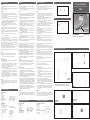
2) The door frame into which the sensors will be
mounted must be perpendicular
to the optical
line (see fig. 1).
3) To protect the receiver and the transmitter against damage, proper fittings
must be used in the installation. UL 325: Minimum height for sensors is 65 mm.
4) The amplifier must be mounted in an appropriate enclosure to protect it
against mechanical as well as alectrical damage and fire.
5) Do not apply power to the amplifier before the sensors are connected.
6) Connect the receiver and the emitter to the terminals that correspond to their
sensor channel number.
7) Apply power to the amplifier. The power LED on the amplifier lights green.
8) The LED´s for the channels connected should be ON (yellow) with no object
present.
Note: For systems with test input as break, be sure that the input is activated.
9) Interrupt each light beam and make sure that the LED relating to that channel
goes out.
10) All sensor versions with connector must be mounted so the connector is
protected from moisture and liquids.
To have a MPF system to operate on a door or gate, the MPF system must be
connected to a Door Controller (See FIG.1).
The Door Controller must check if all relay-contacts are closed before the Door
Controller activates the Test-input on the MPF-amp. When the Test-input is activated
it forces all of the TX (transmitter) to disable. All of the RX (receiver) must indicate
light beam broken and all of the output-relays must release.
The Door Controller must check that all relay contacts are switched off (disconnected)
before the test-signal is deactivated in the Door Controller.
When the Test signal is switched off all off the RX must see light (function OK). The
Door Controller must check that all relays must switch on (connected).
Now all of the MPFTR-system functionality is OK, and the door or gate can be safety
closed.
Testing
1) The function of the system should be tested at max. 6-month intervals.
2) Measure that there is no connection between the relay outputs and
the
corresponding test points while the test input is activated
(see fig. 2)
.
TÜV
Conditions of Application
1) For all outputs which are used for safety-relevant purposes, the application
controller has to check that
a) these outputs are closed before activating the test input of the MPF unit and
b) these outputs are open during activation of the test input of the MPF unit
(test intervals according to risk analysis or EN 12453)
2) A photoelectrical receiver of a MPF system must not see a photoelectrical
transmitter from another MPF system.
3) For each safety relevant application it has to be checked that object detection
does not fail by possible mirror effects around an object (transmitter power
may be reduced to prevent those mirror effects; not adjustable MPF options
may not be usable for short distances).
4) For each safety relevant application it has to be checked that fingertips at a
transmitter are recognized, ie the light must not shine through the fingertips
(transmitter power may be reduced to prevent this; not adjustable MPF options
may not be usable for short distances).
CAUTION
Not for use and mounting as a separate accessory. Only for incorporation by a
professional inside a Door, Drapery, Gate, Louver or Window Operator or System
after evaluation of the Combination (assembly) has shown compliance with the
applicable standards.
Installation Instructions
Connexions
1) Raccorder la tension d’alimentation de l’amplificateur (pour les systèmes CC,
raccorder ”-” à la borne 1 et ”+” à la borne 3).
2) S’assurer que la tension se trouve à l’intérieur des tolérances spécifiées et que
l’installation est realiseé comme exigé par la norme.
Montage
1) Lors de l’installation des détecteurs, s’assurer du non dépassement de l’échelle
maximale, et - si 2 systèmes sont installés côte à côt, faire en sorte de croiser
les cellules émettrices et réceptrices des 2 amplificateurs différents afin
d’éliminer le risque d’inter férence.
2) S’assurer du montage des cellules en respectant la perpendicularité de l’axe
optique par rapport à la platine de fixation (voir fig. 1).
3) Pour protéger le récepteur et l'émetteur contre les dommages, respecter les
normes de chaque pays lors de l'installation.
UL 325 : La hauteur minimum pour les détecteurs étant de 65 mm.
4) L'amplificateur doit être monté dans une armoire appropriée, respectant ainsi
les risques de chocs mécaniques, électriques et d’incendie.
5) Vérifier que l’alimentation de l’amplificateur est coupée avant de raccorder les
détecteurs.
6) Raccorder le récepteur et l’émetteur aux bornes correspondant au numéro de
canal du détecteur respectif.
7) Mettre l’amplificateur sous tension : la LED (verte) d’indication de mise sous
tension de l’amplificateur doit s’allumer.
8) La diode (jaune) de bon alignement des cellules doit s’allume lorsque aucun
objet n’est présent.
Note: Pour les systèmes avec l’entrée test normalement ouverte, s’assurer que
l’entrée est activée.
9) Pour tester vos cellules, interrompre le faisceau lumineux avec un objet et vérifier
que la LED jaune s’éteint.
10) Toutes les versions de détecteur avec connecteur doivent être montées de
telle sorte que le connecteur soit protégé de l’humidité et de tout liquide.
Pour fonctionner avec une porte ou un portail, le système MPF doit être raccordé
à un contrôleur de porte (Fig. 1).
Avant d’activer l’entrée de test de l’ampli MPF, le contrôleur de porte doit au pré-
alable vérifier que tous les contacts de relais sont fermés. Lorsqu’elle est activée,
l’entrée test désactive tous les émetteurs (TX). Le ou les récepteurs (RX) doivent
détecter l’interruption de signal et tous les relais de sortie doivent passer en posi-
tion repos (ouvert).
Le contrôleur de porte doit vérifier que tous les contacts de relais sont au repos
(ouverts) avant désactivation du signal de test par le contrôleur de porte.
Lorsque le signal de test est désactivé, le récepteur doit pouvoir voir la lumière
(fonction OK). Le contrôleur de porte doit vérifier que tous les contacts de relais
sont fermés (connectés).
A ce stade, le système MPFTR est totalement fonctionnel et la porte ou le portail
peuvent être fermés en toute sécurité.
Tests
1) L’entrée test étant activée, mesurer la connexion entre les relais de sortie et
les points de tests correspondants (voir fig. 2).
2) Le système doit être testé à un intervalle maximal de six mois.
TÜV
Conditions d'application
1) Pour toutes les sorties utilisées en mode sécurité, le système de gestion de la
porte doit contrôler que :
a) les sorties de l’amplificateur cellule sont fermées et ce, avant d’avoir active
l’entrée test
b) que les sorties de l’amplificateur cellule s’ouvrent pendant l’activation de
l’entrée test (l’intervalle de ces tests doit être conforme à l’analogue de
risque EN 12453).
2) la cellule réceptrice du premier amplificateur MPF ne doit pas être à proximité
d’un émetteur provenant d’un autre amplificateur MPF.
3) Pour toutes les applications relevant de la sécurité, il doit être contrôlé que
l’objet détecté ne puisse pas être perturbé par des réflecteurs parasites tels
que des miroirs. Dans ce cas, les amplis non ajustables ne doivent pas être
utilisés sur de très courtes distances.
4) Pour toutes les applications relevant de la sécurité, il doit être contrôlé qu’un
doigt d’une main proche de l’émetteur puisse être reconnu et non traversé par
le faisceau (la puissance de l’émetteur peut être réduite afin de prévenir le
risque), les amplificateurs non réglable ne sont pas recommandés pour les
faibles distances.
ATTENTION
Ne jamais utiliser ni mettre en ?uvre un système MPF sous forme d’un simple
accessoire. Confier l’installation uniquement à un professionnel qui l’intègrera à un
actionneur ou à un système de porte, rideau, portail ou fenêtre après évaluation et
mise en conformité de l’ensemble aux normes applicables.
Instructions de Montage
Tension nominale de fonctionnement
Types CA (UB)
Bornes 1 & 3
MPF.- 230 RS. 230 VCA ± 15%, 50 à 60 Hz
MPF.- 115 RS. 115 VCA ± 15%, 50 à 60 Hz
MPF.- 912 RS. 12-24 VCA/CC ± 15%, 50 à 60 Hz
Puissance nominale de fonctionnement
912 115/230
Alimentation CA 3 VA max. 4,5 VA
Alimentation CC 2 W -
Caractéristiques de l’Amplificateur
User Manual GB, D, F
Installationshinweise / Manuel Utilisateur
Anschlüsse
1) Die Versorgungsleitungen an den Verstärker anschliessen (für DC-Systeme –
an Terminal 1, + an Terminal 3).
2) Sicherstellen, dass die Versorgung innerhalb der angegebenen Grenzen liegt
und wie vorgeschrieben verwendet wird.
Montage
1) Bei der Installation der Sensoren ist es wichtig, dass die max. Reichweite nicht
überschrittten wird. Werden zwei getrennte Systeme nah an einander montiert,
müssen die Sensoren so positioniert werden, dass Interferenzen vermieden
werrden.
2) Der Türrahmen, in welchem die Sensoren montiert werden, muss senkrecht auf
der optischen Linie positioniert sein (siehe Fig. 1).
3) Um den Empfänger und den Sender vor Schaden zu schützen, sind in der
Installation die korrekten Montagevorrichtungen zu benutzen. UL 325: Min.
Höhe für Sensoren ist 65 mm.
4) Der Verstärker ist in ein geeignetes Gehäuse zu montieren, um sowohl vor
mechanischen als elektrischen Schaden und Feuer zu schützen.
5) Die Betriebsspannung an den Verstärker nicht anlegen, bis die Sensoren
angeschlossen sind.
6) Den Empfänger und den Sender an den Klemmen der entsprechenden
Sensor-Kanalnummern anschliessen
7) Die Betriebsspannung an den Verstärker anlegen. Die Versorgungs-LED auf
dem Verstärker leuchtet grün.
8) Die gelbe LED der einzelnen Kanäle muss leuchten, wenn kein Objekt
vorhanden ist.
Anmerkung: Für Systeme mit Testeingang als Öffner muss sichergestellt
werden, dass der Eingang aktiviert ist.
9) Lichtstrahl unterbrechen, und sicherstellen, dass die diesem Kanal zugewiesene
LED erlischt.
10) Alle Sensor-Typen mit Stecker müssen so montiert werden, dass der Stecker
vor Feuchtigkeit und Spritzwasser geschützt ist.
Für die Steuerung einer Tür oder eines Tores mit Hilfe eines MPF-Systems ist der
Anschluss an einen Tür-Controller erforderlich.
Dieser kontrolliert, ob alle Relaisschaltkreise geschlossen sind, bevor er das
Test-Signal am MPF-Verstärkereingang schaltet. Nach Anlegung des Test-Signals
erfolgt zwangsweise eine Abschaltung sämtlicher TX-Sender. Bei den RX-
Empfängern muss eine Unterbrechung der Lichtschranke angezeigt werden und
sämtliche Ausgangsrelais müssen schalten.
Der Tür-Controller kontrolliert den abgeschalteten Zustand aller Relaisschalter,
bevor das Test-Signal im Controller deaktiviert wird.
Nach Abschaltung des Test-Signals müssen alle RX aufleuchten (Funktion OK).
Der Tür-Controller kontrolliert, dass alle Relais schalten (angeschlossen).
Die korrekte Funktion des MPFTR-Systems ist somit gewährleistet und die Tür
bzw. das Tor lässt sich jetzt sicher schließen.
Überprüfung
1) Die Funktion des Systems ist mindestens alle 6 Monate zu überprüfen.
2) Überprüfen Sie durch Messung, dass während der Aktivierung des
Testeingangs keine elektrische Verbindung zwischen den Relaisausgängen
und den entsprechenden Testpunkten besteht (siehe Fig. 2).
TÜV
Anwendungsbedingungen
1) Die externe Steuerung (z.B. Tor- oder Antriebssteuerung) muss bei allen
Ausgängen des MPF-Systems folgende Bedingungen überprüfen:
a) diese Ausgänge sind geschossen, bevor der Testeingang der MPF-Einheit
aktiviert wird, und
b) diese Ausgänge werden geöffnet, nachdem der Testeingang der MPF-
Einheit aktiviert wurde (Testintervalle gemäss Risiko-Analyse oder EN12453).
2) Ein Empfänger eines MPF-Systems darf keinen Sender eines anderen MPF-
Systems erkennen (siehe auch Montage Punkt 1)
3) Bei jeder sicherheitsrelevanten Anwendung muss überprüft werden, dass die
Objekterkennung nicht durch mögliche Spiegeleffekte beeinflusst wird (eine
mögliche Abhilfe um diese Spiegeleffekte zu verhindern kann die Reduzierung
der Senderleistung sein; MPF-Systeme ohne die Option eines einstellbaren
Senders sind unter Umständen für kurze Distanzen nicht einsetzbar).
4) Bei jeder sicherheitsrelevanten Applikation muss überprüfen werden, dass das
Abdecken des Senders mit einem Finger erkannt wird (evtl. ist die
Sendeleistung zu reduzieren um ein "durchleuchten" des Fingers zu verhindern;
MPF-Systeme ohne die Option eines einstellbaren Senders sind unter
Umständen für kurze Distanzen nicht einsetzbar).
VORSICHT!
Nicht für separate Anwendung und Montage. Nur von einem autorisierten Monteur
in einer Tür-, Rollladen-, Tor-, Jalousien- oder Fenster-Automatik bzw. -System
nach Überprüfung der Einhaltung einschlägiger Normen und Standards einbauen
lassen.
Installation GB D F Fig.1
Fig. 1
Fig.2
Fig. 2
Test point
Testpunkten
Point de test
Specifications, Amplifier
Rated operational volt.
AC types (UB)
Terminals 1 & 3
MPF.- 230 RS. 230 VAC ± 15%, 50 to 60 Hz
MPF.- 115 RS. 115 VAC ± 15%, 50 to 60 Hz
MPF.- 912 RS. 12-24 VAC/DC ± 15%, 50 to 60 Hz
Rated operational power MPF.-912 MPF.-115/230
AC supply 3 VA max. 4.5 VA
DC supply 2 W -
Output Specifications
Resistive load
MPF.-912 RSL, RSLA, RSLI, RSLAI
600,000 switchings 0.5 A@50 VAC/30 VDC
100,000 switchings 0.5 A@125 VAC/1 A@30 VDC (UL)
MPF.-xxx RS, RSA, RSI, RSAI
600,000 switchings 1 A@250 VAC/30 VDC
300,000 switchings 2 A@250 VAC/30 VDC
100,000 switchings 2 A@250 VAC/30 VDC (UL)
AC15 0.75 A@240 VAC
AC14 0.60 A@120 VAC
DC13 0.22 A@125 VDC
Technische Daten - Verstärker
Nenn-Betriebsspannung.
AC-Typen (UB)
Klemmen 1 & 3
MPF.- 230 RS. 230 VAC ± 15%, 50 bis 60 Hz
MPF.- 115 RS. 115 VAC ± 15%, 50 bis 60 Hz
MPF.- 912 RS. 12-24 VAC/DC ± 15%, 50 bis 60 Hz
Nenn-Betriebsbelastung MPF.-912 MPF.-115/230
Betriebsspannung AC 3 VA max. 4.5 VA
Betriebsspannung DC 2 W -
MPFT 15-4/C
MPFR-4/C
To be mounted in material with a thickness of 0.6 - 2.25 mm
Für den Einbau in Material mit einer Stärke von 0.6 bis 2.25 mm
Pour montage dans des matériaux dúne épaisseur de 0.6 á 2.25 mm
Dimensions / Abmessungen / Dimensions
D11 M14
MPFT 15-M14-4/C
MPFR-M14-4/C
AMPF-MB1
MPFT 15-D18-4/C
MPFR-D18-4/C
Amplifier / Verstärker / Amplificateur

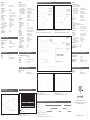
Detection Diagram
Erkennungs-Diagramm / Diagramme de détection
Sensing Range / Reichweite / Gamme de détection
Feet / Fuß / Pied
Rated operating distance (Sn) 15 m (CE)
8 m (UL 325)
Ambient light > 20.000 lux
Degree of protection IP 67 (IEC 60529/ IEC 60947-5-2)
Connection
Cable PVC, grey, 10 m, Ø 2.9 mm2
Temperature See amplifier
Specifications, Sensors
Markings CE, UL
Norms
115/230 EN12453 and UL508
912 EN12453, UL508 and UL325
Markings and Norms
Distance nominale de
fonctionnement (Sn) 15 m (CE)
8 m (UL 325)
Lumière ambiante > 20.000 lux
Indice de protection IP 67 (IEC 60529/ IEC 60947-5-2)
Raccordement Câble PVC, gris, 10 m, 2,9 mm2
Caractéristiques de la Cellule Photoélectrique
Marquages CE, UL
Homologations
115/230 EN12453 and UL508
912 EN12453, UL508 and UL325
Marquages et Homologations
Nenn-Schaltabstand (Reichweite) (Sn) 15 m (CE)
8 m (UL 325)
Umgebungslicht > 20.000 lux
Schutzart IP 67 (IEC 60529/ IEC 60947-5-2)
Anschluss
Kabel PVC, grau, 10 m, Ø 2.9 mm2
Temperatur Siehe Verstärker
Technische Daten - Sender/Empfänger
Abnahmen / Zulassungen CE, UL
Normen
115/230 EN12453 and UL508
912 EN12453, UL508 and UL325
Kennzeichnungen und Normen
Caractéristiques de la sortie
Charge résistive 600.000 commutations
MPF.-912 RSL, RSLA, RSLI, RSLAI
600.000 commutations 0.5 A@50 VCA/30 VCC
100.000 commutations 0.5 A@125 VCA/1 A@30 VCC (UL)
MPF.-xxx RS, RSA, RSI, RSAI
600.000 commutations 1 A@250 VCA/30 VCC
300.000 commutations 2 A@250 VCA/30 VCC
100.000 commutations 2 A@250 VCA/30 VCC (UL)
AC15 0,75 A@240 VCA
AC14 0,60 A@120 VCA
DC13 0,22 A@125 VCC
Fonction de sortie
MPF1+2 Relais 2 x SPST
MPF3 Relais 2 x SPST + 2 x SPST
Indication
Diode (verte) d’alimentation ACTIVE
Diode (jaune) de faisceau allumé (aucun objet détecté)
Température
Fonctionnement -20° à +60°C (-4° à +140°F)
Stockage -30° à +80°C (-22° à +176°F)
Indice de protection IP 40 (IEC 60529/ IEC 60947-5-2)
Raccordement Bornes à vis (max. 2,5 mm2)
Entrée de test
MPF.- 115 RS. Contact exempt de potentiel
MPF.- 230 RS. Contact exempt de potentiel
MPF.- 912 RS. Max. 28 V @ 15 mA CA/CC
Function de test activée ≥ 3.5 V AC/DC
Function de test non activée ≤ 1.0 V AC/DC
MPF.- 912 RSLI. Max. 28 V@15 mA AC/DC
Function de test activée ≥ 3.5 V AC/DC
Function de test non activée ≤ 1.0 V AC/DC
Temps de réponse
OFF-ON (tON) ≤ 50 ms
ON-OFF (tOFF) ≤ 40 ms
Temps de mise sous tension (tv) ≤ 300 ms
Matériau du boîtier PC
Output function
MPF1+2 Relay 2 x SPST
MPF3 Relay 2 x SPST + 2 x SPST
Indication function
Supply ON LED, green
Beam ON (no object present) LED, yellow
Temperature
Operating -20° to +60°C (-4° to +140°F)
Storage -30° to +80°C (-22° to +176°F)
Degree of protection IP 40 (IEC 60529/ IEC 60947-5-2)
Connection Screw terminals (max. 2.5 mm2)
Test input
MPF.- 115 RS. Potential-free contact
MPF.- 230 RS. Potential-free contact
MPF.- 912 RSL. Max. 28 V@15 mA AC/DC
Testfunction activated ≥ 3.5 V AC/DC
Testfunction deactivated ≤ 1.0 V AC/DC
MPF.- 912 RSLI. Max. 28 V@15 mA AC/DC
Testfunction deactivated ≥ 3.5 V AC/DC
Testfunction activated ≤ 1.0 V AC/DC
Response time
OFF-ON (tON) ≤ 50 ms
ON-OFF (tOFF) ≤ 40 ms
Power ON delay (tv) ≤ 300 ms
Housing material PC
Technische Daten - Ausgang
Ohmsche Last
MPF.-912 RSL, RSLA, RSLI, RSLAI
600.000 Schaltvorgänge 0.5 A@50 VAC/30 VDC
100.000 Schaltvorgânge 0.5 A@125 VAC/1 A@30 VDC (UL)
MPF.-xxx RS, RSA, RSI, RSAI
600.000 Schaltvorgänge 1 A@250 VAC/30 VDC
300.000 Schaltvorgänge 2 A@250 VAC/30 VDC
100.000 Schaltvorgânge 2 A@250 VAC/30 VDC (UL)
AC15 0.75 A@240 VAC
AC14 0.60 A@120 VAC
DC13 0.22 A@125 VDC
Ausgangsfunktion
MPF1+2 Relais 2 x Schließer
MPF3 Relais 2 x Schließer + 2 x Schließer
Anzeigefunktion
Betriebsspannung EIN LED, grün
Lichtstrahl EIN
(kein Objekt vorhanden) LED, gelb
Temperatur
Betrieb -20° bis +60°C (-4° bis +140°F)
Lagerung -30° bis +80°C (-22° bis +176°F)
Schutzart IP 40 (IEC 60529/ IEC 60947-5-2)
Anschluss Schraubklemmen (max. 2.5 mm2)
Testeingang
MPF.- 115 RS. potentialfreier Kontakt
MPF.- 230 RS. potentialfreier Kontakt
MPF.- 912 RSL. Max. 28 V@15 mA AC/DC
Testfunktion aktiviert ≥ 3.5 V AC/DC
Testfunktion deaktiviert ≤ 1.0 V AC/DC
MPF.- 912 RSLI. Max. 28 V@15 mA AC/DC
Testfunktion deaktiviert ≥ 3.5 V AC/DC
Testfunktion aktiviert ≤ 1.0 V AC/DC
Ansprechzeit
AUS-EIN (tON) ≤ 50 ms
EIN-AUS (tOFF) ≤ 40 ms
Einschaltverzögerung (tv) ≤ 300 ms
Gehäusematerial PC
GB (cont.) D (forts.) F (suite)
Excess Gain / Funktionsreserve / Excés de Gain
Range / Abstand Sender/Empfänger / Limite
Max. Rating / Max. Nennwert / Valeur maxi
Potentiometer in min. / Potentiometer in Min. /Potentiométre en min.
1
10
100
1000
1000 10000 100000
Range [mm]
Excess gain
Test input make, shown for 115/230 version
Testeingang Schließer für Typ 115/230
Entrée de test active HI, (diagramme de la version 115/230)
1)
Not MPF1 and MPF2
Nicht MPF1 und MPF2
Pas MPF1 et MPF2
2)
Not MPF1 / Nicht MPF1 /
Pas MPF1
Test input make, shown for 912 version
Testeingang Schließer für Typ 912
Entrée de test active HI, (diagramme de la version 912)
Wiring Diagrams / Schaltbilder / Schémas de Câblage
Test input break, shown for 115/230 version
Testeingang Öffner für Typ 115/230
Entrée de test active LO, (diagramme de la version 115/230)
1)
Not MPF1 and MPF2
Nicht MPF1 und MPF2
Pas MPF1 et MPF2
2)
Not MPF1 / Nicht MPF1 /
Pas MPF1
Test input break, shown for 912 version
Testeingang Öffner für Typ 912
Entrée de test active LO, (diagramme de la version 912)
Operation Diagram / Betriebsdiagramm / Diagramme de Fonctionement
Power supply / Betriebsspannung / Alimentation
Object present / Objekt vorhanden / Objet présent
Output contact closed / Ausgang geschaltet / Contact de sortie fermé
Output contact closed
Object present
Power supply
912 version
1)
Not MPF1 and MPF2
Nicht MPF1 und MPF2
Pas MPF1 et MPF2
2)
Not MPF1 / Nicht MPF1 /
Pas MPF1
See Fig. A and B
Siehe Fig. A und B
Voir fig. A et B
Fig. A Fig. B
Max. Rating
------ Potentiometer in min.
15-029-978
MAN MPF GB,D,F rev.14-10.2022
CARLO GAVAZZI
www.gavazziautomation.com
Certified in accordance with ISO 9001
Gerätehersteller mit dem ISO 9001/EN 29 001 Zertifikat
Une société qualifiée selon ISO 9001
-
 1
1
-
 2
2


