Pepperl+Fuchs UBE15M-H1 Bedienungsanleitung
- Typ
- Bedienungsanleitung

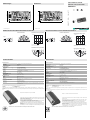
Abmessungen
Elektrischer Anschluss/Kurven/
Zusätzliche Informationen
Electrical Connection / Curves / Additional Information
Dimensions
Technische Daten Technical data
UBE15M-H1
20,2
45
QB1
QA1
QB2
QA2
61
52
43
20.2
45
Q
B1
Q
A1
Q
B2
Q
A2
61
52
43
Takt
Anschluss:
Sender
1
2
43
6
5
-UB+UB
QA
QB
Richtcharakteristik
Dämpfung (dB)
30°
60°
90°
30°
60°
90°
0°
-10 0-20-30
Charakteristische Ansprechkurve
Abstand X [m]
Versatz Y [m]
Möglicher Abstand (Versatz) der optischen
Achsen von Sender und Empfänger.
15
10
5
010 5 -5 -10
Charakteristische Ansprechkurve
15 m 10 m 5 m 5 m 10 m 15 m
30°
45°
60°
Characteristic response curve
Distance X [m]
Offset Y [m]
Permissible distance (offset) between the optical axis of the
emitter and receiver.
15
10
5
010 5 -5 -10
Characteristic response curve
15 m 10 m 5 m 5 m 10 m 15 m
30°
45°
60°
Direction characteristics
Attenuation (dB)
30°
60°
90°
30°
60°
90°
0°
-10 0-20-30
1
2
43
6
5
-UB+UB
QA
QB
Partnummer / Part. No.:
Datum / Date:
109085
02/12/2015 DIN A3 -> DIN
45-2552B
Doc. No.:
Funktion
Der Sender ist Bestandteil eines Komplettsystems aus Sender, Empfänger und Controller
Empfänger: UBE15M-F54-H2-V1
Controller: UH3-16E4A-K15-R3
Durch den Anschluss zweier Wandler kann der Abstrahlbereich durch Ausrichtung in verschiedene Richtungen (zweckmäßigerweise 90°) vergrößert werden.
Achtung:
Bei paralleler Ausrichtung der Wandler kann es zu Interferenzerscheinungen und damit gebietsweiser Verstärkung bzw. Abschwächung des Ultraschall-Signals kom-
men.
Beispiel für eine kundenspezifische Lösung mit 2 Wandlern
Im realen Betrieb werden Sender und Empfänger nicht aufeinander ausgerichtet sein. Dadurch
verringert sich die erzielbare Reichweite
Die nebenstehenden Charakteristischen Ansprechkurven zeigen beispielhaft die Reichweite des
Systems unter folgenden Betriebsbedingungen.
- Sender und Empfänger sind parallel gegenüberliegend angeordnet. Die Kurve
zeigt die Reichweite in Abhängigkeit vom seitlichen Versatz.
- Der Empfänger ist senkrecht nach unten, der Sender in Richtung des
Empfängers angeordnet. Die Kurve zeigt die Reichweite in Abhängigkeit vom
Anstellwinkel.
Hieraus lässt sich die Systemreichweite abhängig von der gegenseitigen Positionierung von Sen-
der und Empfänger für die in der Anwendungspraxis vorkommenden Bedingungen abschätzen.
Zum Anschluss der Geräte dürfen keine Kabeldosen mit integrierten LEDs verwendet werden!
Allgemeine Daten
Erfassungsbereich 0 ... 15000 mm , Sender - Empfänger aufeinander ausgerichtet
Wandlerfrequenz ca. 40 kHz
Öffnungswinkel ± 45 ° bei -6 dB
Temperaturdrift der Echolaufzeit 0,2 %/K
Elektrische Daten
Betriebsspannung UB16 ... 30 V DC , Welligkeit 10 %SS
8 V DC bei geringerer Sendeleistung
Leerlaufstrom I0≤ 10 mA (typ. 6 mA bei UB = 24 V DC)
Eingang
Eingangstyp 1 Impulseingang für Sendeimpuls, Ansteuerung durch open collector npn
< 1,5 V: Sender aktiv, > 3,5 V: Sender inaktiv
Impulsdauer 100 µs ... 10 ms
Pausendauer ≥ 50 x Impulsdauer
Umgebungsbedingungen
Umgebungstemperatur 0 ... 50 °C (32 ... 122 °F)
Lagertemperatur -40 ... 85 °C (-40 ... 185 °F)
Mechanische Daten
Schutzart IP00
Anschluss Steckkontakte und Lötflächen
Masse 20 g
Abmessungen Platine: 45 mm x 20,2 mm (5 mm abtrennbar: 40 mm x 20,2 mm)
Bauhöhe: 10 mm
Zulassungen und Zertifikate
UL-Zulassung cULus Listed, General Purpose
CSA-Zulassung cCSAus Listed, General Purpose
CCC-Zulassung Produkte, deren max. Betriebsspannung ≤36 V ist, sind nicht zulassungspflichtig und daher nicht mit einer CCC-
Kennzeichnung versehen.
Information
Function
The emitter is part of a complete system consisting of emitter, receiver and controller
Receiver: UBE15M-F54-H2-V1
Controller: UH3-16E4A-K15-R3
By means of using 2 ultrasonic transducers, aligned to different directions (practically 90° angular difference), the detection range and the angular tolerance can be
increased anymore.
Caution:
When aligning both ultrasonic transducers in a parallel way, mutual interference effects can occur. This can cause local amplification respective attenuation of the
ultrasonic sound strength.
Example of a customized solution with 2 ultrasonic transducers
In real operation, the transmitter and receiver will not be not aligned to each other. This will reduce
the detection range.
The characteristic response curve to the side illustrates examples of the detection range of the sys-
tem under the following operating conditions.
- The transmitter and receiver are arranged so they lie parallel opposite each
other. The graph shows the detection range as a function of lateral offset.
- The receiver is arranged vertically downwards, while the emitter is arranged in
the direction of the receiver. The graph shows the detection range as a function of
the angle of incidence.
This makes it possible to evaluate the detection range of the system as a function of the positioning
of the transmitter and receiver for conditions that will occur in practical usage.
Cable sockets with built-in indicator LEDs must not be used to connect this device!
General specifications
Sensing range 0 ... 15000 mm , emitter - receiver synchronised
Transducer frequency approx. 40 kHz
Angle of divergence ± 45 ° at -6 dB
Temperature drift of echo propagation delay 0.2 %/K
Electrical specifications
Operating voltage UB16 ... 30 V DC , ripple 10 %SS
8 V DC with reduced transmitting power
No-load supply current I0≤ 10 mA (typ. 6 mA at UB = 24 V DC)
Input
Input type 1 pulse input for transmitter pulse, activation through open collector npn
< 1.5 V: emitter active, > 3.5 V: emitter inactive
Pulse length 100 µs ... 10 ms
Pause length ≥ 50 x pulse length
Ambient conditions
Ambient temperature 0 ... 50 °C (32 ... 122 °F)
Storage temperature -40 ... 85 °C (-40 ... 185 °F)
Mechanical specifications
Degree of protection IP00
Connection Contact plugs and soldering surfaces
Mass 20 g
Dimensions Printed circuit board: 45 mm x 20.2 mm (5 mm separable: 40 mm x 20.2 mm)
overall height: 10 mm
Approvals and certificates
UL approval cULus Listed, General Purpose
CSA approval cCSAus Listed, General Purpose
CCC approval CCC approval / marking not required for products rated ≤36 V
Information
Ultraschallsensor, Sender
Ultrasonic sensor, transmitter
Alle Abmessungen in mm All dimensions im mm

Adressen / Addresses / Adresses / Direcciónes / Indirizzi
Contact Pepperl+Fuchs GmbH · 68301 Mannheim · Germany · Tel. +49 621 776-4411 · Fax +49 621 776-27-4411 · E-mail: fa-info@de.pepperl-fuchs.com
Worldwide Headquarters: Pepperl+Fuchs GmbH · Mannheim · Germany · E-mail: [email protected]l-fuchs.com
USA Headquarters: Pepperl+Fuchs Inc. · Twinsburg · USA · E-mail: fa-in[email protected].com
Asia Pacific Headquarters: Pepperl+Fuchs Pte Ltd · Singapore · E-mail: [email protected]perl-fuchs.com · Company Registration No. 199003130E
For more contact-adresses refer to the catalogue or internet: http://www.pepperl-fuchs.com
-
 1
1
-
 2
2


Pepperl+Fuchs UBE15M-H1 Bedienungsanleitung
- Typ
- Bedienungsanleitung
in anderen Sprachen
Verwandte Artikel
-
Pepperl+Fuchs UBE15M-F54-H2-V1 Bedienungsanleitung
-
-
-
-
-
-
-