Seite wird geladen ...

- 1 -
Bestimmungsgemäße Verwendung
Das Temperaturüberwachungsrelais
S1MS Ex dient in Temperaturüber-
wachungsschaltungen nach EN 44 081 als
Schutzeinrichtung vor Überhitzung für
Antriebe, Generatoren, Ölbehälter (z. B. in
Transformatoren), Lagerräume u. ä.
Das Temperaturüberwachungsgerät ist ein
zugehöriges Betriebsmitel zum Auswerten
von Sensoren und ist bestimmt für den
Einsatz als
• Motorschutzrelais
• Auslöseeinrichtung bei Erreichen der
Übertemperatur
• Motorschutz für explosionsgeschützte
Antriebe
Das Temperaturüberwachungsrelais stellt
einen eigensicheren Ausgangsstromkreis für
explosionsgefährdete Bereiche nach
(ATEX) zur Verfügung (verwendete Normen:
EN 60079-0:2012, EN 60079-11:2012).
ACHTUNG!
Gerät immer außerhalb des
explosionsgefährdeten Bereichs bzw.
in einem Ex-geschützten Einbauraum
montieren. Nur der eigensichere
Ausgangsstromkreis (Klemmen T1,
T2) darf in den explosions-
gefährdeten Bereich (Zone 2 bzw.
22) geführt werden.
Die Anschlussklemmen des eigen-
sicheren Ausgangsstromkreises
müssen durch den Trennkammerauf-
satz von den nicht eigensicheren
Stromkreisen getrennt sein.
Das Gerät wurde nach Richtlinie
(ATEX) durch TÜV Product Service GmbH
geprüft.
Zu Ihrer Sicherheit
• Installieren und nehmen Sie das Gerät
nur dann in Betrieb, wenn Sie diese
Betriebsanleitung gelesen und verstan-
den haben und Sie mit den geltenden
Vorschriften über Arbeitssicherheit und
Unfallverhütung vertraut sind.
Sie müssen ebenfalls mit den Explosions-
schutzanforderungen vertraut sein.
Beachten Sie die VDE- sowie die örtlichen
Vorschriften, insbesondere hinsichtlich der
Schutzmaßnahmen.
• Halten Sie beim Transport, bei der
Lagerung und im Betrieb die Bedingun-
gen ein, wie sie unter "Technische Daten"
angegeben sind.
• Montieren Sie das Gerät in einen Schalt-
schrank; Staub und Feuchtigkeit können
sonst zu Beeinträchtigungen der Funktio-
nen führen.
• Sorgen Sie an allen Ausgangskontakten
bei kapazitiven und induktiven Lasten für
eine ausreichende Schutzbeschaltung.
• Öffnen Sie nicht das Gehäuse und
nehmen Sie auch keine eigenmächtigen
Umbauten vor.
19856-3FR-03
S1MS Ex
4
D Betriebsanleitung
4
GB Operating instructions
4
F Manuel d'utilisation
Intended Application
The S1MS Ex is a Thermistor Protection
Relay in accordance with EN 44 081 for
protection against overheating in drives,
generators, oil containers (e.g. in
transformers), storage areas etc.
The temperature monitoring relay is a
corresponding resource for evaluating
sensors and is designed for use as:
• A motor protection relay
• A trip device when overtemperature is
reached
• Motor protection for drives with explosion
protection
The thermistor monitoring relay provides an
intrinsically safe output circuit for potentially
explosive areas in accordance with
(ATEX) (standards applied:
EN 60079-0:2012, EN 60079-11:2012).
CAUTION!
The unit should always be installed
outside the potentially explosive area
or inside an Ex-protected space. Only
the intrinsically safe output circuit
(terminals T1, T2) may be brought
into the potentially explosive area
(Zone 2 / 22).
The connection terminals on the
intrinsically safe output circuit must be
separated from non-intrinsically safe
circuits using a separating chamber
attachment.
The relay was inspected in accordance with
Directive by TÜV Product
Service GmbH.
For your safety
• Only install and commission the unit if
you have read and understood these
instructions and are familiar with both
these instructions and the current
regulations for health and safety at work
and accident prevention.
You also need to be familiar with
explosion protection requirements. Follow
VDE and local regulations especially
regarding preventive measures.
• Transport, storage and operating
conditions should all conform to the
standards as stated under “Technical
details”.
• The unit should be panel mounted,
otherwise dampness or dust could lead to
malfunction of the unit.
• Adequate protection must be provided for
all capacitive and inductive consumers.
• Do not open the housing or undertake any
unauthorised modifications.
• Please make sure you shut down the
supply voltage, or open the input circuit
when performing maintenance work
(e.g. when replacing contactors). In case
of a wiring error, the device might switch
on unexpectedly.
Domaines d’utilisation
Le relais S1MS Ex est un dispositif de
protection destiné à surveiller la
température de moteurs électriques, de
générateurs, de réservoirs d’huile (ex.
transformateurs), de dépots de stockage
etc... selon la norme EN 44 081.
Ce relais de surveillance de la température
est un appareil auxiliaire servant à l’analyse
de capteurs. Il peut être utilisé comme
• relais de protection moteur
• dispositif de déclenchement en cas de
surtempérature
• relais de protection pour moteur en zone
ex
Le relais de surveillance de température
fournit un circuit de mesure, de sécurité
intrinsèque, pour les atmosphères explosi-
bles selon la norme
(normes utilisées :
EN 60079-0:2012, EN 60079-11:2012).
ATTENTION !
Montez impérativement l'appareil en
dehors de l'atmosphère explosible ou
dans un lieu d'implantation avec
protection Ex. Seul le circuit de
mesure, de sécurité intrinsèque
(bornes T1, T2), peut être câblé dans
la zone présentant des risques
d'explosion (zone 2 ou 22).
Les borniers de raccordement du
circuit de mesure de sécurité
intrinsèque doivent être séparés des
circuits de sécurité non intrinsèques
par une chambre de séparation.
Cet appareil a été contrôlé par TÜV Product
Service GmbH conformément à la directive
.
Pour votre sécurité
• Vous n’installerez l’appareil et ne le
mettrez en service qu’après avoir lu et
compris le présent manuel d’utilisation et
que si vous êtes familier avec les
prescriptions en vigueur sur la sécurité du
travail et la prévention d’accidents.
Vous devez également être familier avec
les exigences concernant la protection
contre les explosions. Tenez compte des
normes locales ou VDE applicables,
notamment en ce qui concerne la
sécurité.
• Pour le transport, le stockage et
l'utilisation, respectez les exigences des
normes specifiées (voir „Caractéristiques
techniques“).
• Montez l’appareil dans une armoire
électrique à l’abri de l’humidité et de la
poussière.
• Veillez à ce que les consommateurs
capacitifs et inductifs aient une protection
suffisante.
• N’ouvrez pas le boîtier et n'effectuez pas
de modifications non autorisées.
4
2014/34/EU (ATEX)
2014/34/EU
2014/34/EU
2014/34/EU (ATEX)
2014/34/EU
2014/34/EU (ATEX)

- 2 -
• En cas de travaux de maintenance (par
ex. remplacement des contacteurs) coupez
impérativement la tension d’alimentation ou
ouvrez le circuit d’entrée, sinon un
réarmement inopiné du relais est possible
en cas d’erreur de câblage.
Respectez impérativement les avertisse-
ments
dans les autres paragraphes du
présent manuel d’utilisation. Ces
avertissements sont signalés par des
symboles visuels.
Description de l’appareil
Inséré dans un boîtier S-95, le relais de
surveillance de température est disponible
en 5 versions pour les tensions alternatives
et une version pour le tension continue et
alternatif.
Particularités:
• Contacts de sortie:
2 OF (inverseurs)
• Circuit de mesure pour le câblage d’une
sonde CTP
• Réarmement automatique
• LEDs de visualisation présence tension
d'alimentation
• LED d’indication du défaut
• Zones Ex:
- II (3) G [Ex ic] IIC Gc
- II (3) D [Ex ic] IIIC Dc
Le relais répond aux exigences de sécurité
suivantes:
• Indication du défaut par retombée du
relais de sortie
• Protection de l’installation garantie en cas
de:
- défaillance tension d’alimentation
- défaillance bobine
- défaut soudure
You must take note of the warnings given in
other sections of these operating
instructions. These are highlighted visually
through the use of symbols.
Description
The Thermistor Protection Relay is enclosed
in a S-95 housing. There are 5 versions
available for AC operation and 1 version for
DC and AC operation.
Features:
• Relay contacts:
2 auxiliary contacts (2 C/O)
• Measuring circuit for connection of a
temperature sensor (PTC-resistance)
• Automatic reset
• LED display for operating voltage
• error indicating LED
• Ex areas:
- II (3) G [Ex ic] IIC Gc
- II (3) D [Ex ic] IIIC Dc
The unit complies with the following safety
requirements:
• Normally energised mode
• Protection of the monitored unit is
maintained in the following cases:
- Loss of voltage
- Coil defect in a relay
- Cable break
• Schalten Sie bei Wartungsarbeiten (z. B.
beim Austausch von Schützen) unbedingt
die Versorgungsspannung ab oder öffnen
Sie die Eingangskreise, sonst kann das
Gerät bei Verdrahtungsfehlern unerwartet
einschalten.
Beachten Sie unbedingt die Warnhinweise
in den anderen Abschnitten dieser Anlei-
tung. Diese Hinweise sind optisch durch
Symbole hervorgehoben.
Gerätebeschreibung
Das Temperaturüberwachungsrelais ist in
einem S-95-Gehäuse untergebracht. Es
stehen 5 Varianten für den Betrieb mit
Wechselspannung und eine Variante für
den Betrieb mit Gleich- und Wechsel-
spannung zur Verfügung.
Merkmale:
• Relaisausgänge:
2 Hilfskontakte (2 U)
• Messkreis für den Anschluss eines
Temperaturfühlers (PTC- Widerstand)
• automatischer Reset
• LED zur Versorgungsspannungsanzeige
• LED zur Störungsanzeige
• Ex-Bereiche:
- II (3) G [Ex ic] IIC Gc
- II (3) D [Ex ic] IIIC Dc
Das Gerät erfüllt folgende Sicherheitsanfor-
derungen:
• Funktion nach dem Ruhestromprinzip
• Schutz der zu überwachenden Anlage ist
gewährleistet bei:
- Spannungsausfall
- Spulendefekt
- Leiterbruch
Fig. 1: Schematisches Schaltbild
S1MS
G1
F1
K1
T1 T2
K1
J > NAT
Messkreis
Measuring Circuit
Circuit mesure
+
~
=
A2
(-)
A1
(+)
B
U
12 14
11
22 24
21
*
Fig. 1: Wiring diagram Fig. 1: Schéma interne
Eigensicherer Bereich/Intrinsically
safe area/Zone à sécurité intrinsèque
* Isolation zum nicht markierten Bereich und der
Relaiskontakte zueinander: Basisisolierung
(Überspannungskategorie III), sichere Trennung
(Überspannungskategorie II)
* Insulation between the non-marked area
and the relay contacts: Basic insulation
(overvoltage category III), safe separation
(overvoltage category II)
* Isolation de la partie non sélectionnée par
rapport aux contacts relais : isolation
basique (catégorie de surtensions III),
isolation galvanique (catégorie de
surtensions II)

- 3 -
Funktionsbeschreibung
Das Temperaturüberwachungsrelais schützt
elektrische Antriebe, Generatoren, Ölbehäl-
ter in Transformatoren, Lagerräume u. ä.
vor Überhitzung. Dazu wird der Wider-
standswert R
th
eines Temperaturfühlers
(PTC-Widerstand) ausgewertet, der sich
bei Temperaturzunahme vergrößert. Bei
Erreichen der Nennansprechtemperatur
(Ansprechwert R
an
) löst das Gerät aus.
Solange die Nennansprechtemperatur nicht
überschritten ist (R
th
< R
an
) und die Versor-
gungsspannung am Gerät anliegt, ist das
Ausgangsrelais K1 im Arbeitszustand. Die
Kontakte 11-14 und 21-24 sind geschlos-
sen, die Kontakte 11-12 und 21-22 sind
geöffnet.
Bei Überschreiten der Nennansprech-
temperatur fällt das Ausgangsrelais ab
(Ruhezustand). Die Kontakte 11-14 und
21-24 öffnen, die Kontakte 11-12 und 21-22
schließen und die rote LED leuchtet. Das
Gerät startet automatisch, sobald sich der
Temperaturfühler auf die Rücksetz-
temperatur (R
th
≤ R
an
) abgekühlt hat.
Function Description
The Thermistor Protection Relay protects
against overheating in electric drives, gene-
rators, oil containers in transformers,
storage areas etc. The resistance value R
th
of a temperature sensor (PTC-resistance) is
evaluated, which increases with the
increase in temperature. When the nominal
energisation temperature is reached (trip
resistance R
an
), the unit is triggered.
As long as the temperature has not
exceeded the nominal energisation
temperature (R
th
<R
an
) and the operating
voltage is connected to the unit, the output
relay K1 is in the operating position. The
contacts 11-14 and 21-24 are closed, the
contacts 11-12 and 21-22 are open.
If the nominal response value is exceeded,
the output relay de-energises (rest position).
The contacts 11-14 and 21-24 open, the
contacts 11-12 and 21-22 close and the red
LED illuminates. The unit automatically
becomes ready for operation, as soon as
the temperature sensor has cooled down to
the nominal de-energisation temperature
(R
th
≤ R
ab
).
Description du fonctionnement
Le relais de surveillance de température
S1MS Ex protège les moteurs éléctriques,
les générateurs, les réservoirs d’huiles des
transformateur etc. contre une surchauffe.
Pour cela, le S1MS Ex surveille la valeur de
résistance R
th
de la sonde de température
CTP. Lorsque la température s’élève, la
résistivité de la sonde augmente jusqu’à la
valeur de déclenchement R
an
qui fait
retomber le relais.
A la mise sous tension du relais, si la
température est inférieure au seuil de
déclenchement (R
th
< R
an
), le relais de sortie
K1 passe en position travail.
Les contacts 11-14 et 21-24 se ferment et
les contacts 11-12 et 21-22 s’ouvrent.
Si la température depasse le seuil de
déclenchement, le relais de sortie retombe.
Les contacts 11-14/21-24 s’ouvrent et les
contacts 11-12/21-22 se ferment. La LED
rouge s’allume.
Le relais est réarmé automatiquement dès
que la sonde de température est refroidie
(R
th
≤ R
ab
).
Fig. 2: Funktionsdiagramm
U
B
= Versorgungsspannung/Operating Voltage/Tension d'alimentation
R
an
= Ansprechwert/Response value/Valeur d’enclenchement
R
ab
= Rücksetzwert/Release value/Valeur de retombée
R
th
= PTC-Widerstandswert/PTC-Resistance value/Valeur de résistance CTP
Fig. 2: Diagramme fonctionnelFig. 2: Functional diagram
nicht speichernd/non-latching/
non mémorisé
U
B
R
th
R
an
R
ab
11 - 14
+
21 - 24

- 4 -
Montage
• Montieren Sie das Gerät in einen
Schaltschrank mit einer Schutzart von
mindestens IP54
- der den Ex e-Anforderungen nach
EN 60079-7:2007 entspricht
oder
- der in einem trockenen Raum steht, der
regelmäßig gereinigt wird. Es dürfen
keine nennenswerten Staubab-
lagerungen oder Feuchteinwirkungen
auftreten.
• Befestigen Sie das Gerät mithilfe des
Rastelements auf der Rückseite auf einer
Normschiene.
• Sichern Sie das Gerät bei Montage auf
einer senkrechten Tragschiene (35 mm)
durch ein Halteelement (z. B. Endhalter
oder Endwinkel)
ACHTUNG!
• Gerät immer außerhalb des explosions-
gefährdeten Bereichs bzw. in einem Ex-
geschützten Einbauraum montieren. Nur
der eigensichere Ausgangsstromkreis
(Klemmen T1 und T2) dürfen in den
explosionsgefährdeten Bereich geführt
werden.
• Die Verdrahtung muss den Anforderungen
nach EN 60079-11:2012 Abs. 6.3.12
genügen.
Inbetriebnahme
Beachten Sie bei der Inbetriebnahme:
• Die Ausgangskontakte 11-12/14 und
21-22/24 sind Hilfskontakte (2 U, z. B. für
Anzeige oder Schützansteuerung).
• Vor die Ausgangskontakte eine
Sicherung (siehe technische Daten)
schalten, um das Verschweißen der
Kontakte zu verhindern.
• Leitungsmaterial aus Kupferdraht mit
einer Temperaturbeständigkeit von
60/75 °C verwenden.
• Der Ex-Schutz wird nur erreicht, wenn alle
Bedienelemente, die an den nicht
eigensicheren Bereich (s. Fig. 1) ange-
schlossen sind, in einem Ex-geschützten
Raum montiert werden. Für die
Anschlusselemente des eigensicheren
Bereichs ist kein Ex-Schutz notwendig.
• Die Anschlussklemmen des eigensicheren
Ausgangsstromkreises müssen durch den
Trennkammeraufsatz von den nicht
eigensicheren Stromkreisen getrennt sein.
Beachten Sie die Anschlussreihenfolge im
nächsten Abschnitt "Anschluss".
• Anschlussteile für äußere eigensichere
Stromkreise: zwischen blanken Teilen des
eigensicheren Stromkreises und blanken
Teilen des nicht eigensicheren Stromkrei-
ses mind. 50 mm Abstand einhalten oder
durch eine Trennwand nach EN 60079-
11:2012 Abs. 6.2.1 trennen.
• Hinweis für Gerätevariante 24 V AC/DC:
Bei Einsatz an Ex e-Motoren ist der
Betrieb nur in einem Batterienetz oder
Netz zulässig, welches mit Sicherheitstrafo
aufgebaut ist.
Installation
• Install the safety relay in a control cabinet
with a minimum protection type of IP54
- that meets the requirements of Ex e in
accordance with EN 60079-7:2007
or
- that is located in a dry room that is
cleaned regularly. No notable dust
deposits or humidity effects must be
allowed to occur.
• Use the notch on the rear of the unit to
attach it to a DIN-rail.
• Attach the unit securely to a vertical DIN
rail (35 mm) using a fixture such as a
retaining bracket or end angle.
CAUTION!
• The unit should always be installed outside
the potentially explosive area or inside an
Ex-protected space. Only the intrinsically
safe output circuit (terminals T1, T2) may
be brought into the potentially explosive
area.
• The wiring must meet the requirements of
EN 60079-11:2012, Clause 6.3.12.
Operation
Please note for operation:
• The output contacts 11-12/14 and
21-22/24 are auxiliary contacts (2 C/O,
e.g. for signalling or contactor control).
• To prevent contact welding, a fuse
(see Technical Details) must be
connected before the output contacts.
• Use copper wiring that can withstand
60/75 °C.
• Ex-protection is only achieved if all
operator elements connected to the non-
intrinsically safe area (see Fig. 1) are
installed in an Ex-protected space.
Elements connected to the intrinsically
safe area do not require Ex-protection.
• The connection terminals on the
intrinsically safe output circuit must be
separated from non-intrinsically safe
circuits using a separating chamber
attachment. Please note the connection
sequence described below under
"Connection".
• Connectors for external intrinsically safe
circuits: Maintain a min. distance of 50 mm
between uninsulated parts of the intrinsi-
cally safe circuit and uninsulated parts of
the non-intrinsically safe circuit, or use a
partition to separate them in accordance
with EN 60079-11:2012 section 6.2.1.
• Note for 24 V AC/DC device type:
When used on Ex e motors, operation is
only permitted on a battery or mains
supply which is designed with a safety
transformer
Montage
• Installer le bloc logique de sécurité dans
une armoire ayant un indice de protection
IP54 au minimum
- qui correspond aux exigences EX e
conformément à l'EN 60079-7:2007
ou
- qui se trouve dans une pièce dépourvue
d'humidité et régulièrement nettoyée.
Aucun dépôt de poussière notable, ni
impact dû à l'humidité ne doit se
produire.
• Montez l'appareil sur un rail DIN à l'aide
du système de fixation situé au dos du
relais.
• Fixer l’appareil sur un rail DIN vertical (35
mm) avec un élément de maintien comme
par ex. un support ou une équerre
terminale.
ATTENTION !
• Monter impérativement l'appareil en
dehors de l'atmosphère explosible ou dans
un lieu d'implantation avec protection Ex.
Seul le circuit de mesure, de sécurité
intrinsèque (bornes T1 et T2), peut être
câblé dans la zone présentant des risques
d'explosion.
• Le câblage doit satisfaire aux exigences
de l'EN 60079-11:2012, paragraphe
6.3.12.
Mise en oeuvre
Remarques préliminaires:
• Les contacts de sortie 11-12/14 et
21-22/24 sont des contacts d’information
(2 OF, par ex. pour la signalisation ou le
pilotage de contacteur).
• Protéger les contacts de sortie par des
fusibles (voir "Charactéristiques
techniques") pour éviter leur soudage.
• Utiliser uniquement des fils de cablâge en
cuivre 60/75 °C.
•
La protection Ex n’est obtenue que si tous
les éléments de commande qui sont
raccordés à la zone non de sécurité
intrinsèque (voir fig. 1) sont montés dans un
local protégé Ex. Les éléments de raccorde-
ment de la zone à sécurité intrinsèque n’ont
pas besoin d’une protection Ex.
• Les borniers de raccordement du circuit de
mesure de sécurité intrinsèque doivent
être séparés des circuits de sécurité non
intrinsèques par une chambre de
séparation. Veuillez tenir compte de l'ordre
de raccordement présenté dans le
prochain paragraphe « Raccordement ».
•
Éléments de raccordement pour des circuits
externes à sécurité intrinsèque : respectez
une distance minimale de 50 mm entre les
parties dénudées du circuit à sécurité
intrinsèque et les parties dénudées de l’un
des circuits non de sécurité intrinsèque ou
mettez en place une cloison de séparation
conforme à la norme
EN 60079-11:2012 art. 6.2.1.
• Remarque concernant le modèle
d'appareil 24 V AC/DC :
Si on l'utilise sur des e-moteurs Ex, le
fonctionnement est uniquement autorisé
dans un réseau de piles ou un réseau
conçu avec un transformateur de sécurité.

- 5 -
• Bei 24 V AC/DC-Geräten:
Das Netzteil muss den Vorschriften für
Funktionskleinspannungen mit sicherer
elektrischer Trennung (SELV, PELV)
nach VDE 0100, Teil 410 entsprechen.
• Angaben im Kapitel "Technische Daten"
unbedingt einhalten.
Anschluss
Nehmen Sie den Trennkammeraufsatz ab.
Verdrahten Sie zuerst die unteren Klem-
men:
• Versorgungsspannung an Klemmen A1
(+) und A2 (-) anschließen.
• Ausgangskontakte entsprechend der
jeweiligen Anwendungsschaltung
anschließen (Klemmen 11, 21, 22 und
24).
Setzen Sie den Trennkammeraufsatz wie in
der Abbildung dargestellt auf. Die blau
markierten Klemmen T1 und T2 müssen
durch die Trennkammer abgedeckt sein.
• Messkreis:
Temperaturfühler (PTC-Widerstand) an
die Klemmen T1 und T2 anschließen.
• Ausgangskontakte entsprechend der
jeweiligen Anwendungsschaltung
anschließen (Klemmen 12 und 14).
• For 24 V AC/DC units:
The power supply must comply with the
regulations for extra low voltages with safe
electrical separation (SELV, PELV) in
accordance with VDE 0100, Part 410.
• Important details in the section "Technical
Details" should be noted and adhered to.
Connection
Remove the separating chamber
attachment. Wire the lower terminals first:
• Connect the supply voltage to terminals
A1 (+) and A2 (-).
• Connect the output contacts in
accordance with the relevant application
circuit (terminals 11, 21, 22 and 24).
Fit the separating chamber attachment as
shown in the diagram. The separating
chamber must cover the terminals
highlighted in blue, T1 and T2.
• Measuring circuit:
Connect the temperature sensor (PTC
resistor) to terminals T1 and T2.
• Connect the output contacts in
accordance with the relevant application
circuit (terminals 12 and 14).
• Pour 24 V appareils AC/DC:
L'alimentation doit satisfaire aux
prescriptions relatives aux tensions extra
basses avec une isolation électrique de
sécurité (SELV, PELV) selon VDE 0100,
partie 410.
• Respecter les données indiquées dans le
chapitre „Caractéristiques techniques“.
Branchement
Enlevez la chambre de séparation. Câblez
dans un premier temps les bornes du
dessous :
• Appliquer la tension d'alimentation aux
bornes A1 (+) et A2 (-).
• Raccorder les contacts de sortie au circuit
d'application correspondant (bornes 11,
21, 22 et 24).
Posez la chambre de séparation comme
représenté sur l'illustration. Les bornes T1
et T2 marquées en bleu doivent être
couvertes par la chambre de séparation.
• Circuit de mesure :
Raccorder la sonde de température
(résistance CTP) aux bornes T1 et T2.
• Raccorder les contacts de sortie au circuit
d'application correspondant (bornes 12 et
14).
Ablauf
Die grüne LED leuchtet, sobald die
Versorgungsspannung eingeschaltet wird.
Die Kontakte 11-14 und 21-24 sind ge-
schlossen und die Kontakte 11-12 und 21-
22 sind geöffnet. Bei Übertemperatur öffnen
die Kontakte 11-14 und 21-24, die Kontakte
11-12 und 21-22 schließen. Die rote LED
leuchtet.
To operate
The green LED illuminates as soon as the
operating voltage is connected. The
contacts 11-14 and 21-24 are closed and
the contacts 11-12 and 21-22 are open. In
the case of overtemperature, the contacts
11-14 and 21-24 open, the contacts 11-12
and 21-22 close. The red LED illuminates.
Fonctionnement
La LED verte s’allume dès que la tension
d’alimentation est appliquée. Les contacts
11-14/21-24 sont fermés et les contacts
11-12/21-22 sont ouverts. En cas de
surtempérature, les contacts 11-14/21-24
s’ouvrent et les contacts 11-12/21-22 se
ferment. La LED rouge s’allume.
Fig. 3: Anschluss Trennkammeraufsatz/Connecting the separating chamber attachment/Pose de la chambre de séparation

- 6 -
Anwendung
Das Schaltungsbeispiel in Fig. 4 ist eine
typische Anwendung für das S1MS Ex. Löst
das S1MS Ex bei Übertemperatur aus, so
fällt der Motorschütz K2 ab und kann erst
nach der Beseitigung der Störung wieder
angesteuert werden.
Application
The example in Fig. 4 is a typical application
for the S1MS Ex. If the S1MS Ex is
triggered by over temperature, the motor
relay K2 de-energises and can only be re-
energised once the fault has been removed.
Utilisation
L’exemple de câblage (Fig. 4) est une
utilisation type du S1MS Ex. Lorsque le
S1MS Ex déclenche en cas de
surtempérature, le contacteur moteur K2
retombe. Le moteur ne pourra alors être
remis sous tension que si le défaut a
disparu.
Fig. 4: Anwendungsschaltung
Application diagram
Schéma d'application
M1
K2
F2
H1
S2
K2
K2
M 3 AC
U
V
W
J JJ
S2
L1
L2
L3
1L1
(1L+)
B
U
1L2
(1L-)
0V
11 21
T1
12 14 T2
22 24 A2
A1
S1MS
Überprüfung - Fehlerursachen
Durch Unterbrechen des Messkreises kann
überprüft werden, ob das Gerät ordnungs-
gemäß abschaltet.
Das Gerät geht aus Sicherheitsgründen bei
folgenden Fehlern nach einer Störung nicht
wieder in den betriebsbereiten Zustand:
• Leitungsunterbrechung im Messkreis
• der Kaltwiderstand R
k
der Temperatur-
fühler ist zu groß (siehe techn. Daten)
Mögliche Abhilfe: Die Temperaturfühler
auf zwei Temperaturüberwachungsgeräte
verteilen
• ein Temperaturfühler ist hochohmig
• Defekt am Temperaturüberwachungs-
relais
Muss das Gerät ausgetauscht werden oder
die Verdrahtung geändert werden, entfernen
Sie zuerst die Leitungen der oberen
Klemmen. Ziehen Sie den Trennkammerauf-
satz ab und entfernen Sie dann die Leitun-
gen der unteren Klemmen.
Testing - Fault causes
To test the correct de-energisation of the
unit, interrupt the measuring circuit.
For safety reasons, the unit does not return
to operating position after the following
faults:
• Cable break in the measuring circuit
• The PTC resistance R
k
of the temperature
sensor is too high (see Technical Details)
Possible remedy: Split the temperature
sensors between two thermistor
protection units
• A temperature sensor is highly resistive
• A defect in the thermistor protection relay
If you need to exchange the device or
change the wiring, remove the wires from
the upper terminals first. Remove the
separating chamber attachment and then
remove the wires from the lower terminals.
Vérification - sources d’erreur
On vérifie, par l’ouverture du circuit de
mesure si le relais retombe correctement.
Le relais se met en position défaut, bien qu’il
n’y ait aucune surtempérature et ne se laisse
pas réarmer dans les cas suivants:
• coupure du circuit mesure
• la résistance à froid de la sonde CTP est
plus grande que la résistance d’enclen-
chement R
an
(voir „Caractéristiques
techniques“).
Conseil: partager la sonde sur deux
relais de surveillance température.
• défaillance de la sonde de température
• défaut dans le relais de surveillance de
température.
Si l'appareil doit être remplacé ou si le
câblage doit être modifié, veuillez retirer
d'abord les conducteurs ou les bornes
situées au-dessus. Ôtez la chambre de
séparation et retirez ensuite les conducteurs
des bornes situés en dessous.

- 7 -
Kennzeichnung
Die Kennzeichnung der Geräte wird im
Tampon- bzw. Thermoprintverfahren
dauerhaft lesbar auf Seite und Front
aufgebracht. Sie enthält folgende Ex-
spezifische Angaben:
• ATEX-Kategorien:
- II (3) G [Ex ic] IIC Gc
- II (3) D [Ex ic] IIIC Dc
• Hersteller:
Pilz GmbH & Co., D-73760 Ostfildern
• Herstellungsjahr / Fertigungsnr.:
Kann aus fortlaufender sechsstelliger
Seriennr. ermittelt werden. Jeder Seriennr.
ist eindeutig eine Stückliste mit Fertigungs-
datum hinterlegt.
• CE-Zeichen
Technische Daten
Eigensichere Stromkreise
• Eigensicherer Ausgangsstromkreis,
Anschluss über Klemmen T1, T2
- Zündschutzart/Gruppe: [Ex ic] IIC/IIIC
- Ausgangsspannung U
o
: max. 16 V DC -
eigensicher
- Ausgangssstromstärke I
o
: max. 3 mA
- Ausgangsleistung P
o
: max. 12 mW
- lineare Ausgangskennlinie
- Max. Werte der äußeren Kapazität und
Induktivität:
[Ex ic] IIC: Co=0,5 µF; Lo=500 µH
Nichteigensichere Stromkreise
• Nichteigensicherer Versorgungs-
stromkreis, Anschluss über Klemmen A1
und A2. Max. Versorgungsspannung U
m
:
U
B
+ Spannungstoleranz (s. technische
Daten)
- Umgebungstemperaturbereich: -10 bis
+55 °C
- Schutzart: Gehäuse IP40, Klemmen-
bereich IP20
• Nichteigensichere Kontaktstromkreise,
Anschluss über Klemmen 11, 12, 14 und
21, 22, 24
- Schaltvermögen:
AC 240 V / 5 A / 1200 VA,
DC 24 V / 5 A / 120 W
- Absicherung der Kontaktstrecken: 4 A T
Identification
The unit identification is permanently marked
on the front and side using tampon/thermal
printing. It contains the following Ex-specific
details:
• ATEX categories:
- II (3) G [Ex ic] IIC Gc
- II (3) D [Ex ic] IIIC Dc
• Manufacturer:
Pilz GmbH & Co., D-73760 Ostfildern
• Year of manufacture/production no.:
Can be identified from the six-digit serial
number. Each serial number is unique and
is stored in a parts list with the production
date.
• CE mark
Technical details
Intrinsically safe circuits
•
Intrinsically safe output circuit, connection
via terminals
T1, T2
- ignition protection type/group:
[Ex ic] IIC/IIIC
- output voltage U
o
: max. 16 V DC -
intrinsically safe
- output current strength I
o
: max. 3 mA
- output power P
o
: max. 12 mW
- linear output characteristic
- max. values of external capacitance and
inductance:
[Ex ic] IIC: Co=0,5 µF; Lo=500 µH
Non-intrinsically safe circuits
• Non-intrinsically safe supply circuit,
connection via terminals A1 and A2. Max.
supply voltage U
m
: U
B
+ voltage tolerance
(see technical details).
- Ambient temperature range: -10 to
+55 °C
- protection type: housing IP40, terminals
IP20
• Non-intrinsically safe contact circuits,
connection via terminals 11, 12, 14 and 21,
22, 24
- switching capability:
AC 240 V / 5 A / 1200 VA,
DC 24 V / 5 A / 120 W
- protection of contact paths: 4 A T
Identification
L’identification des appareils est apposée sur
le côté et sur la face avant, à l’aide d’un
procédé par tampon ou par impression
thermique, pour être lisible en permanence.
Elle contient les indications Ex spécifiques
suivantes :
• Catégories ATEX :
- II (3) G [Ex ic] IIC Gc
- II (3) D [Ex ic] IIIC Dc
• Fabricant :
Pilz GmbH & Co., D-73760 Ostfildern
•
Année de fabrication/numéro de fabrication:
identifiable à partir du numéro de série
séquentiel à 6 chiffres. Pour chaque
numéro de série, une liste contenant les
données de fabrication est enregistrée.
• Symbole CE
Caractéristiques techniques
Circuits à sécurité intrinsèque
• Circuit de sortie à sécurité intrinsèque,
raccordement par les bornes T1, T2
- Type de protection/groupe :
[Ex ic] IIC/IIIC
- Tension de sortie U
o
: max. 16 V DC -
sécurité intrinsèque
- Courant de sortie I
o
: max. 3 mA
- Puissance de sortie P
o
: max. 12 mW
- Caractéristique de sortie linéaire
- Valeur maximale de la capacité et de
l’inductance externes :
[Ex ic] IIC: Co=0,5 µF; Lo=500 µH
Circuits non de sécurité intrinsèque
• Circuit d’alimentation non de sécurité
intrinsèque, raccordement par les bornes
A1 et A2. Tension d'alimentation max.
U
m
: U
B
+ tolérance de tension (voir les
caractéristiques techniques).
- Plage de température ambiante : -10 à
+55 °C
- Indice de protection : boîtier IP40,
bornier IP20
•
Circuits de contact non de sécurité
intrinsèque, raccordement par les bornes
11, 12, 14
et
21, 22, 24
- Caractéristiques de commutation :
AC 240 V / 5 A / 1200 VA,
DC 24 V / 5 A / 120 W
-
Protection par fusible des contacts : 4 A T

- 8 -
Technische Daten
Versorgungsspannung U
B
Spannungstoleranz U
B
Frequenzbereich
Restwelligkeit U
B
Leistungsaufnahme bei U
B
Ausgangskontakte
Hilfskontakt (U)
Gebrauchskategorie nach
EN 60947-4-1
EN 60947-5-1
Kontaktmaterial
Kontaktabsicherung extern nach
EN 60947-5-1
Schmelzsicherung flink
Schmelzsicherung träge
Sicherungsautomat
Charakteristik B/C
Mechanische Lebensdauer, Zyklen
Anzugsverzögerung
Hysterese
Ansprechwert R
an
Rücksetzwert R
ab
Kaltwiderstand R
k
bei 20° C
Max. zulässiger Einschaltstrom
Luft- und Kriechstrecken
Verschmutzungsgrad
Überspannungskategorie
Bemessungsisolationsspannung
Bemessungsstoßspannungs-
festigkeit
Klimabeanspruchung
EMV
Schwingungen nach
Frequenz
Amplitude
Umgebungstemperatur
Lagertemperatur
Schutzart
Einbauraum (z. B. Schaltschrank)
Gehäuse
Klemmenbereich
Max. Querschnitt des Außenleiters
(Schraubklemmen)
1 Leiter
flexibel
2 Leiter gleichen Querschnitts
flexibel mit Aderendhülse ohne
Kunststoffhülse
flexibel mit TWIN-Aderendhülse
Anzugsdrehmoment für
Schraubklemmen
Gehäusematerial
Front
Gehäuse
Abmessungen (Schraubklemmen)
Gewicht
AC: 48 V, 110 V, 230 V, 240 V
AC/DC: 24 V
-15 %/ +10 %
50 - 60 Hz
max. 160 %
AC: 3,5 VA
DC: 2 W
2
AC1: 240 V/0,1 ... 5 A/1200 VA
DC1: 24 V/0,1 ... 5 A/120 W
AC15: 230 V/2 A;
DC13: 24 V/1,5 A
AgCdO + 3,0 µm Au
6 A
4 A
4 A
10 x 10
6
ca. 500 ms
3,6 kOhm, ± 10 %
1,8 kOhm, ± 10 %
max. 1,5 kOhm
10 A AC
EN 60947-1, EN 60079-11
2
III / II
250 V
4,00 kV
EN 60068-2-78
EN 60947-5-1, EN 61000-6-2
EN 60068-2-6
10 ... 55 Hz
0,35 mm
-10 ... +55 °C
-40 ... +85 °C
IP54
IP40
IP20
0,20 ... 4,0 mm
2
/24-10 AWG
0,20 ... 2,5 mm
2
/24-14 AWG
0,20 ... 2,5 mm
2
/24-14 AWG
0,6 Nm
ABS UL 94 V0
PPO UL 94 V0
siehe Abbildung/see diagram/
voir l'illustration
AC: 175 g, DC: 130 g
Technical Details
Supply voltage U
B
Voltage tolerance U
B
Frequency range
Residual ripple U
B
Power Consumption at U
B
Output contacts
Auxiliary contact (C/O)
Usage category acc. to
EN 60947-4-1
EN 60947-5-1
Contact material
External Contact Fuse Protection
EN 60947-5-1
Blow-out fuse quick acting
Blow-out fuse slow acting
Safety cut-out characteristic B/C
Mechanical life, cycles
Delay on energisation
Hysteresis
Response value R
an
Release value R
ab
Resistance R
k
at 20° C
Max. permitted inrush current
Airgap creepage
Pollution degree
Overvoltage category
Rated insulation voltage
Rated impulse withstand voltage
Climatic suitability
EMC
Vibration to
Frequency
Amplitude
Ambient temperature
Storage temperature
Protection type
Mounting (e.g. control cabinet)
Housing
Terminals
Max. Cable cross section (screw
terminals)
1 core
flexible
2 core, same cross section
flexible with crimp connectors,
without insulating sleeve
flexible with TWIN crimp
connectors
Torque setting for screw terminals
Housing material
front panel
housing
Dimensions (screw terminals)
Weight
Caractéristiques techniques
Tension d’alimentation U
B
Plage de la tension
d’alimentation U
B
Fréquence
Ondulation résiduelle U
B
Consommation pour U
B
Contacts de sortie
Contacts d’information (OF)
Catégorie d'utilisation selon
EN 60947-4-1
EN 60947-5-1
Matériau des contacts
Protection des contacts
EN 60947-5-1
Fusible rapide
Fusible normal
Dijoncteur caractéristiques B/C
Durée de vie mécanique, cycles
Temps de montée
Hystérésis
Valeur d'enclenchement R
an
Valeur de retombée R
ab
Résistance à froid R
k
pour 20° C
Pouvoir de coupure admissible max.
Cheminement et claquage
Niveau d'encrassement
Catégorie de surtensions
Tension assignée d'isolement
Tension assignée de tenue aux
chocs
Sollicitations climatiques
CEM
Vibrations selon
Fréquence
Amplitude
Température d’utilisation
Température de stockage
Indice de protection
Lieu d'implantation (par
ex. armoire)
Boîtier
Borniers
Max. Capacité de raccordement
(borniers à vis)
1 conducteur
souple
2 câbles de même diamètre
souple avec embout sans
chapeau plastique
souple avec embout TWIN
Couple de serrage (borniers à vis)
Matériau du boîtier
face avant
boîtier
Dimensions (borniers à vis)
Poids
Es gelten die 2012-11 aktuellen Ausgaben
der Normen.
The version of the standards current at
2012-11 apply.
Se référer à la version des normes en
vigeur au 2012-11.

- 9 -
Typ/
Type/
Type
S1MS Ex
S1MS Ex
S1MS Ex
S1MS Ex
S1MS Ex
Merkmale/
Features/
Caractéristiques
24 V AC/DC
48 V AC
110 V AC
230 V AC
240 V AC
Klemmen/
Terminals/
Borniers
Schraubklemmen/screw terminals/borniers à vis
Schraubklemmen/screw terminals/borniers à vis
Schraubklemmen/screw terminals/borniers à vis
Schraubklemmen/screw terminals/borniers à vis
Schraubklemmen/screw terminals/borniers à vis
Bestell-Nr./
Order no./
Référence
839 775
839 725
839 740
839 760
839 765
Bestelldaten/Order reference/Caractéristiques
Bestelldaten Zubehör/Order reference: Accessories/Références des accessoires
Typ/
Type/
Type
Ex separating chamber attachment
Merkmale/
Features/
Caractéristiques
Trennkammeraufsatz/separating chamber attachment/chambre de séparation
Bestell-Nr./
Order no./
Référence
839 399

- 10 -
112.5
25.739
87.8
5.2
0
120.627
134.6
4.4
35.4
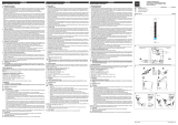
4GB Dimensions in mm (") 4F Dimensions en mm (")4D Abmessungen in mm (")
4GB Connector pin assignment 4F Affectation des raccords4D Anschlussbelegung

- 11 -
EG-Konformitätserklärung:
Diese(s) Produkt(e) erfüllen die Anforderun-
gen der Richtlinie des
europäischen Parlaments und des Rates.
Die vollständige EG-Konformitätserklärung
finden Sie im Internet unter www.pilz.com
Bevollmächtigter: Norbert Fröhlich,
Pilz GmbH & Co. KG, Felix-Wankel-Str. 2,
73760 Ostfildern, Deutschland
EC Declaration of Conformity:
This product/these products meet the
requirements of the directive
(ATEX) of the European Parliament and of
the Council.
The complete EC Declaration of Conformity
is available on the Internet at www.pilz.com
Authorised representative: Norbert Fröhlich,
Pilz GmbH & Co. KG, Felix-Wankel-Str. 2,
73760 Ostfildern, Germany
Déclaration de conformité CE :
Ce(s) produit(s) satisfait (satisfont) aux
exigences à la directive
du Parlement européen et du Conseil.
Vous trouverez la déclaration de conformité
CE complète sur notre site internet
www.pilz.com
Représentant : Norbert Fröhlich,
Pilz GmbH & Co. KG, Felix-Wankel-Str. 2,
73760 Ostfildern, Allemagne
2014/34/EU (ATEX)
2014/34/EU (ATEX)
2014/34/EU
/