
Installation and Removal Instructions
for Series NRX Spring Release, Latch
Check Switch and Motor Operator
• WARNING
(1) ONLY QUALIFIED ELECTRICAL PERSONNEL SHOULD BE PERMITTED TO WORK
ON THE EQUIPMENT.
(2) ALWAYS DE-ENERGIZE PRIMARY AND SECONDARY CIRCUITS IF A CIRCUIT
BREAKER CANNOT BE REMOVED TO A SAFE WORK LOCATION.
(3) DRAWOUT CIRCUIT BREAKERS SHOULD BE LEVERED (RACKED) OUT TO THE
DISCONNECT POSITION.
(4) ALL CIRCUIT BREAKERS SHOULD BE SWITCHED TO THE OFF POSITION AND
MECHANISM SPRINGS DISCHARGED.
FAILURE TO FOLLOW THESE STEPS FOR ALL PROCEDURES DESCRIBED IN THIS
INSTRUCTION LEAFLET COULD RESULT IN DEATH, BODILY INJURY, OR PROPERTY
DAMAGE.
• WARNING
THE INSTRUCTIONS CONTAINED IN THIS IL AND ON PRODUCT LABELS HAVE TO
BE FOLLOWED. OBSERVE THE FIVE SAFETY RULES:
– DISCONNECTING
– ENSURE THAT DEVICES CANNOT BE ACCIDENTALLY RESTARTED
– VERIFY ISOLATION FROM THE SUPPLY
– EARTHING AND SHORT-CIRCUITING
– COVERING OR PROVIDING BARRIERS TO ADJACENT LIVE PARTS
DISCONNECT THE EQUIPMENT FROM THE SUPPLY. USE ONLY AUTHORIZED
SPARE PARTS IN THE REPAIR OF THE EQUIPMENT. THE SPECIFIED MAINTENANCE
INTERVALS AS WELL AS THE INSTRUCTIONS FOR REPAIR AND EXCHANGE MUST
BE STRICTLY ADHERED TO PREVENT INJURY TO PERSONNEL AND DAMAGE TO
THE SWITCHBOARD.
Instructions apply to:
1600 NRX SUB-TITLE IMAGE (12/15/2010)
Series NRX, Type NF Frame
ANSI, UL1066, UL489 / IEC, IZMX16, IZM91
Series NRX, Type RF Frame
IEC, IZMX40
4000 NRX RF DRAWOUT SUBTITLE IMAGE (12/15/2010)
effective January 2013 Series NRXInstruction Leaet IL01301010E

2
Installation and Removal Instructions
for Series NRX Spring Release, Latch
Check Switch and Motor Operator
EATON CORPORATION www.eaton.com
Instruction Leaet IL01301010E
effective January 2013
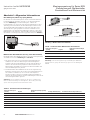
Section 1: General information
Spring release (SR)
A spring release is recommended for electrically operated circuit
breakers, although it is an optional device (Figure 1). It remotely
closes the circuit breaker when the coil is energized by a voltage input.
When a latch check switch is installed, the closing spring must be fully
charged and the trip latch reset (not held in the tripped position) for the
SR to operate. If these two conditions are not met, the close signal
will be ignored until it is removed and re-applied (Table 1).
Figure 1. Spring Release
Latch check switch (LCS)
A latch check switch indicates when the circuit breaker is “ready to
close” (Figure 2 and Table 2).Two versions of the LCS are available:
1. Internal—The LCS wired to the spring release will not permit
activation of the spring release until the circuit breaker is fully
charged and the trip latch is reset. The LCS is supplied with two
leads and a small 2-pin connector.
2. External—The LCS used for remote indication consists of one
Form C contact wired to the circuit breaker secondary contacts for
integration into external control schemes.
Note: Wiring the LCS for remote indication directly in series with the SR
accessory is not recommended as this will override the “anti-pump” feature. The
LCS is supplied with three leads and two secondary connectors.
Figure 2.
External LCS
Internal LCS
Latch Check Switches
Table 1. Latch Check Ratings
Control Voltage Frequency Contact Rating (Amperes)
250 50–60 Hz 10
125 DC 0.5
250 DC 0.25
Note: Many illustrations use the NF Frame 1600A circuit breaker for illustrative
purposes only. The RF Frame 4000A circuit breaker is handled in a similar
fashion.
Table 2. Spring Release Ratings
Control Voltage Frequency
Operational Voltage (Range
85–110%)
Inrush Power Consumption
(VA) Closing Time (ms)
24 DC 20–26 400 25
48 DC 41–53 500 25
60 DC 51-66 500 25
110–127 50–60 Hz 94–140 750 25
110–125 DC 94–138 750 25
208–240 50–60 Hz 177–264 800 25
220–250 DC 187–275 800 25

3
Instruction Leaet IL01301010E
effective January 2013
Installation and Removal Instructions
for Series NRX Spring Release, Latch
Check Switch and Motor Operator
EATON CORPORATION www.eaton.com
Section 2: Installation of spring release
Proceed with the following eight steps:
Step 1: Remove the four screws holding the front cover in place (two
on each side of the cover).
Figure 3. Step 1
Step 2: Remove the front cover. Pull down on the charging handle to
simplify removal.
Figure 4. Step 2
Step 3: To gain access to the mounting location, pull the charging
handle down as shown in Figure 5.
Figure 5.
SR Mounting Location
Step 3
Step 4: Position the spring release as shown to begin the installation
process (Figure 6).
Note: The spring release is secured in its mounted position with one captive
retaining screw.
Figure 6.
Captive Mounting Screw
Step 4

4
Installation and Removal Instructions
for Series NRX Spring Release, Latch
Check Switch and Motor Operator
EATON CORPORATION www.eaton.com
Instruction Leaet IL01301010E
effective January 2013
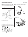
Step 5: While pulling back on the manual charging handle, tilt the
spring release backward so it fits into and under the slot feature on the
breaker sideplate as shown.
Figure 7. Step 5
Step 6: Complete the mounting process by pushing the spring release
forward and securing it in place with its captive retaining screw. Use a
screwdriver to hand tighten the retaining screw.
Step 7: Make the appropriate secondary connections as outlined
in Section 9. If necessary, bundle secondary wires using industry-
accepted wire tie practices.
Step 8: Replace the front cover and secure it in place with the four
mounting screws previously removed in Step 1.
Section 3: Removal of spring release
Proceed with the following four steps:
Step 1: Remove the front cover from the breaker by first performing
Steps 1 and 2 of Section 2.
Step 2: Locate the spring release and disconnect the appropriate
secondary connection as described in Section 9.
Figure 8.
Spring Release
Step 2
Step 3: Unscrew the captive retaining screw from the spring release
and remove the spring release. Pulling forward on the manual charging
handle simplifies removal.
Step 4: If another spring release is to be installed, perform Steps
3 through 8 of Section 2. If not, complete the removal operation by
performing Step 8 of Section 2.
Section 4: Installation of latch check
switch in spring release
Proceed with the following five steps:
Step 1: Remove the spring release from the breaker prior to installing
a latch check switch by performing Steps 1 through 3 of Section 3.
Step 2: Position the spring release as shown. Tilt the latch check switch
back to properly position it for final installation. The LCS is shown
without leads soldered to appropriate terminals for clarity purposes
(Figure 9).
Figure 9. Step 2
Step 3: Carefully press the latch check switch down as shown until a
snapping sound is heard. This sound indicates the switch is properly
seated (Figure 10).
Figure 10. Step 3

5
Instruction Leaet IL01301010E
effective January 2013
Installation and Removal Instructions
for Series NRX Spring Release, Latch
Check Switch and Motor Operator
EATON CORPORATION www.eaton.com
Step 4: If the latch check switch being installed is for use internally
in conjunction with the spring release, plug the small 2-pin connector
of the latch check switch into the 2-pin plug in the spring release. The
2-pin connector only fits one way and will latch into place. If the latch
check switch being installed is for use externally, skip this step and
proceed to Step 5. Keep in mind that separate secondary connections
with an externally mounted LCS will have to be made as part of Step
5.
Figure 11.
2-Pin Plug for Internal
LCS Connection
Step 4
Step 5: With the latch check switch now installed in the spring release,
repeat Steps 3 through 8 of Section 2.
Section 5: Removal of latch check switch
from spring release
Proceed with the following five steps:
Step 1: Remove the spring release from the breaker prior to removing
a latch check switch by performing Steps 1 through 3 of Section 3.
Step 2: If the latch check switch is internally connected to the spring
release, unplug its connector from the 2-pin plug in the spring release.
Figure 12.
2-Pin Plug for LCS Connection
Step 2
Step 3: With the spring release positioned as shown, pull back on the
locking tab to unlock the latch check switch from the spring release.
Figure 13. Step 3
Step 4: Tilt the latch check switch back and lift to release and remove
it from the spring release.
Figure 14. Step 4
Step 5: If another latch check switch is to be installed in the spring
release, perform Steps 2 through 5 of Section 4. If not, just reinstall
the spring release by performing Steps 3 through 8 of Section 2.

6
Installation and Removal Instructions
for Series NRX Spring Release, Latch
Check Switch and Motor Operator
EATON CORPORATION www.eaton.com
Instruction Leaet IL01301010E
effective January 2013
Section 6: Motor operator general infor-
mation
A motor operator is an electric motor assembly internally mounted in
the right-hand side of the circuit breaker (Figure 15). It charges the
closing springs electrically for remote or local operation. The motor
operator can be factory or field installed (Table 3 NF and Table 4 RF).
If a motor operator is being installed in the field, an optional spring
release device can also be installed. Instructions for the installation of
a spring release are provided in Section 2 of this document.
Figure 15.
Motor
Operator
Motor Operator Location
Section 7: Installation of motor operator
Proceed with the following 11 steps:
Step 1: Remove the four screws holding the front cover in place (two
on each side of the cover).
Figure 16. Step 1
Step 2: Remove the front cover. Pull down on the charging handle to
simplify removal.
Table 3. Motor Operator Ratings - NF
Control Voltage Frequency
Operational Voltage
(Range 85–110%)
Run Current
(Amperes) Typ. Inrush Current
Power
Consumed
(VA)
Max. Charge
Time (sec)
24 DC 20–26 6 325% 160 4
48 DC 41–53 3 500% 150 3
60 DC 51-66 2 350% 150 4
110–127 50–60 Hz 94–140 2 300% 280 3
110–125 DC 94–138 1 500% 150 3
208–240 50–60 Hz 177–264 1 1000% 280 4
220–250 DC 187–275 1 1000% 280 4
Table 4. Motor Operator Ratings - RF
Control Voltage Frequency
Operational Voltage
(Range 85–110%)
Run Current
(Amperes) Typ. Inrush Current
Power
Consumed
(VA)
Max. Charge
Time (sec)
24 DC 20–26 7 350% 200 6
48 DC 41–53 3 450% 175 6
60 DC 51-66 3 450% 225 6
110–127 50–60 Hz 94–140 3 300% 425 6
110–125 DC 94–138 2 375% 275 6
208–240 50–60 Hz 177–264 1.5 300% 400 6
220–250 DC 187–275 1 400% 250 6

7
Instruction Leaet IL01301010E
effective January 2013
Installation and Removal Instructions
for Series NRX Spring Release, Latch
Check Switch and Motor Operator
EATON CORPORATION www.eaton.com
Figure 17. Step 2
Step 3: If an existing motor operator is already installed, remove it first
by following the instructions outlined in Section 8. If not, proceed with
Step 4.
Step 4: To simplify installation, examine the motor operator to verify
that the hub key on the motor operator is in the proper position. It is
properly positioned if the arrowhead on the hub key lines up with the
hole in the hub housing as shown. If they are aligned, proceed to Step
6.
Figure 18.
Hub Key
Arrowhead
Hole
Step 4
Step 5: If the arrowhead and hole are not aligned, rotate the hub key
clockwise using any appropriate tool to achieve alignment.
Figure 19. Step 5
Step 6: With the arrowhead and hole aligned, push on the two captive
mounting screws until they are nearly flush with their mounting collars.
This will simplify the Step 7 mounting process.
Figure 20.
Mounting Screw
Mounting Screw
Step 6
Step 7: For the NF Frame, align the hub key on the motor operator
with the key on the cam shaft and push the motor operator into its
mounted position. For the RF Frame, align the hub key on the motor
operator with the key in the cam shaft and position the motor operator
so the black actuator lever rests on the pin and is settled in the
mounted position.
• IMPORTANT
IT IS IMPORTANT THAT THE TWO KEYS ARE PROPERLY ALIGNED AND MATE
EASILY BEFORE TIGHTENING THE MOUNTING SCREWS IN STEP 8.

8
Installation and Removal Instructions
for Series NRX Spring Release, Latch
Check Switch and Motor Operator
EATON CORPORATION www.eaton.com
Instruction Leaet IL01301010E
effective January 2013
Figure 21.
Cam Shaft
Key
Hub
Key
Step 7. NF Frame
Figure 21a. Step 7. RF Frame
Step 8: Use an Allen wrench to screw the captive mounting screws
(2 screws for NF and 3 screws for RF) of the motor operator into
the already tapped mounting holes in the circuit breaker. Firmly hand
tighten the two mounting screws.
Figure 22. Step 8
Step 9: The installed motor operator should look as shown with
secondary leads extending up and ready to be made.
Figure 23. Step 9
Step 10: Make the appropriate secondary connections as outlined
in Section 9. If necessary, bundle secondary wires using industry-
accepted wire tie practices.
ote:N If an externally wired latch check switch and a motor operator are installed
together, a simple secondary wiring change must be made. Remove the latch
check switch’s secondary connector plug as described in Section 9. Once
removed, disconnect the latch check switch’s secondary lead (#40-NF, #54-RF)
from the connector plug by inserting the terminal extraction tool (included in
the externally wired latch check switch kit) into the end of the connector plug
as shown. The tool releases the lead so it can be removed from the other end.
The connector plug can be discarded. The latch check switch’s disconnected
lead (#40-NF, #54-RF) is now reconnected into the open secondary location
in the motor operator’s connector plug. No tool is required to make this
connection. It is, however cautioned that the connector plug must be oriented
as shown in Figure 26 before making the connection. Gently push the lead into
the connector’s open spot, and it will easily connect and lock into place.
Rotate motor
operator to rest
black actuator
on pin
Motor operator
Pin
Black actuator
lever

9
Instruction Leaet IL01301010E
effective January 2013
Installation and Removal Instructions
for Series NRX Spring Release, Latch
Check Switch and Motor Operator
EATON CORPORATION www.eaton.com
Figure 24.
#40-NF
#54-RF
Open
Secondary
#39-NF
#53-RF
Step 10
Figure 25. Step 10
Secondary
Lead
Connector
Plug
Terminal
Extraction
Tool
Figure 26. Step 10
Step 11: Replace the front cover, and secure it in place with the four
mounting screws previously removed in Step 1.
Section 8: Removal of motor operator
Proceed with the following five steps:
Step 1: If necessary, remove the front cover from the breaker by
performing Steps 1 and 2 of Section 2.
Step 2: Locate the motor operator and disconnect the appropriate
secondary connections as described in Section 9.
Figure 27. Step 2
Step 3: Remove the motor operator from the circuit breaker by using
an Allen wrench to unscrew the captive motor operator mounting
screws (2 screws for NF and 3 screws for RF).
Figure 28. Step 3
Step 4: Complete removal of the motor operator by pulling it out
(Figure 29).

10
Installation and Removal Instructions
for Series NRX Spring Release, Latch
Check Switch and Motor Operator
EATON CORPORATION www.eaton.com
Instruction Leaet IL01301010E
effective January 2013
Figure 29. Step 4
Step 5: Repeat Steps 4 through 11 of Section 7 if another motor
operator is to be installed. If not, just complete Step 11 of Section 7.
Section 9: Accessory secondary
connections
General information
1. Electrical accessory leads are tagged with numbers associated
with the applicable connection diagram located in instruction book
MN01301001E (NF) and MN01301003E (RF). Leads are also supplied
with keyed secondary connector plugs to ensure proper connections
(Figure 30).
2. Secondary connections are made by plugging the connector plugs
into the appropriate location. A connector plug already connected
can be removed by squeezing two release tabs together with small
needle nose pliers and pulling out (Figure 31).
Figure 30.
Tagged
Leads
Keyed
Connector
1
1
2
2
Leads and Connectors
Figure 31.
2
Release
Tabs
Connector Plug Removal
Fixed breaker connections
Proceed with the following five steps:
Step 1: Become familiar with the fixed terminal block DIN rail type
mounting plate where secondary connections are made.
ote:N Secondary connection points have numerical and descriptive laser-etched
identifications.
Figure 32.
4
3
5
7
9
11
13
15
17
19
21
23
25
27
OT1M
OT2B
OT2M
ALM1
ALM2
ALMC
OT2C
OT1B
OT1C
N2
G2
G1
N1
SGF1
AGND
CMM2
CMM1
+24V
SGF2
CMM4
CMM3
ZOOM
ZOUT
UV2
UV1
6
8
10
12
14
16
18
20
22
24
26
28
30
32
34
9
11
13
15
17
19
21
23
25
27
OT2B
OT2M
ALM1
ALM2
ALMC
OT2C
OT1B
N2
G2
G1
N1
SGF1
AGND
CMM2
CMM1
+24V
SGF2
CMM3
8
10
12
14
16
18
20
22
Step 1
Step 2: Plug the accessory connector plug into the fixed secondary
terminal block.

11
Instruction Leaet IL01301010E
effective January 2013
Installation and Removal Instructions
for Series NRX Spring Release, Latch
Check Switch and Motor Operator
EATON CORPORATION www.eaton.com
Figure 33.
Fixed Secondary
Terminal Block
1
2
Step 2
Step 3: Identify the correct mounting location on the fixed terminal
block mounting plate for mounting the fixed secondary terminal block.
Insert the bottom end of the fixed secondary terminal block into the
proper location on the DIN rail type mounting plate.
Figure 34.
Flexible Mounting Tabs
3
1
5
7
9
1
1
13
15
17
19
21
23
25
27
OT1M
OT2B
OT2M
ALM1
ALM2
ALMC
OT2C
OT1B
OT1C
N2
G2
G1
N1
SGF1
AGND
CMM2
CMM1
+24V
SGF2
CMM4
CMM3
ZOOM
ZOU
T
UV1
8
10
12
14
16
18
20
22
24
26
28
30
32
34
13
14
Step 3
Step 4: Rotate the top end of the terminal block in until it engages the
appropriate flexible mounting tab at the top of the mounting plate. A
clicking sound will be heard if done properly.
Figure 35.
4
3
1
5
7
9
1
1
13
15
17
19
21
23
25
27
6
10
12
14
16
18
20
22
24
26
28
30
32
34
14
13
Step 4
• IMPORTANT
TO REMOVE RIGHT AND LEFT ACCESSORY TRAYS OR ANY OTHER
ELECTRICAL ACCESSORY, THE APPROPRIATE ACCESSORY CONNECTOR PLUG
MUST FIRST BE DISCONNECTED.
Step 5: To remove an accessory plug on a fixed circuit breaker, the
appropriate fixed secondary terminal block must first be removed. To
remove a fixed secondary terminal block, lift up on the small flexible
mounting tab at the top of the fixed terminal block mounting plate, and
rotate the terminal block out in the opposite direction shown in Figure
35. Once the terminal block is removed, the accessory connector plug
can be unplugged from the bottom of the terminal block. Refer to
Item 2 and Figure 31 under the heading “General information” in this
section for detailed assistance with the removal.
Drawout breaker connections
Proceed with the following three steps:
Step 1: Become familiar with the drawout secondary plug housing
where secondary connections are made.
ote:N Secondary connection points have numerical and descriptive laser-etched
identifications on top of the housing directly matching the plug-in locations
below.
Figure 36.
1
2
4
3
5
6
7
8
9
10
12
14
16
11
13
15
17
18
19
20
21
22
CMM2
DNGA
1FGS
G2
N2
N1
ALM2
ALM1
OT2M
OT2B
OT1M
UV2
ST2
ST1
UV1
OT1C
OT1B
OT2C
ALMC
G1
SGF2
+24V
CMM1
Step 1
Step 2: Match the numbers on the secondary leads with the numbers
etched on the top of the secondary housing, and insert the connector
plug into the associated slot.

12
Installation and Removal Instructions
for Series NRX Spring Release, Latch
Check Switch and Motor Operator
EATON CORPORATION www.eaton.com
Instruction Leaet IL01301010E
effective January 2013
Figure 37.
1
2
Step 2
• IMPORTANT
TO REMOVE RIGHT AND LEFT ACCESSORY TRAYS OR ANY OTHER
ELECTRICAL ACCESSORY, THE APPROPRIATE ACCESSORY CONNECTOR PLUG
MUST FIRST BE DISCONNECTED.
Step 3: To remove an accessory connector plug on a drawout circuit
breaker, unplug it from its secondary plug housing. Refer to Item 2 and
Figure 31 under the heading “General information” in this section for
detailed assistance with the removal.
Section 10: Spring release/latch check/
motor operator testing
• IMPORTANT
BEFORE PERFORMING ANY TEST ACTIVITIES, LEVER A DRAWOUT CIRCUIT
BREAKER TO THE TEST POSITION. FOR FIXED TYPE CIRCUIT BREAKERS,
MAKE SURE PRIMARY CIRCUITS ARE DE-ENERGIZED.
Spring release testing
1. Verify that the circuit breaker is in the Open position. Charge the
breaker’s closing spring using the manual charging handle.
2. Apply rated voltage to the spring release and verify that the breaker
toggles to the Closed position.
Spring release with internal latch check switch testing
Place the circuit breaker in the different positions shown in Table 5 and
apply rated voltage to the spring release.
ote:N The voltage needs to be removed from the spring release before it can be
applied each time.
Table 5. Testing Sequence with Internal Latch Check Switch
Initial Breaker
Position Spring Release Result Final Breaker Position
OPEN,
discharged
Does not
actuate
No change
OPEN, charged Actuates Closed
CLOSED,
discharged
Does not
actuate
No change
CLOSED, charged Actuates Attempts to close again
Hold OPEN button,
discharged
Does not
actuate
No change
Hold OPEN button,
charged
Does not
actuate
No change
Spring release with external latch check switch testing
Place the circuit breaker in the different positions shown in Table 6 and
check the continuity between the leads shown in the table.
Table 6. Testing Sequence with External Latch Check Switch
Initial Breaker
Position
NF
Continuity Between Red (42)
and Black (41) Leads
RF
Continuity Between Red (56)
and Black (55) Leads
NF
Continuity Between Blue
(40) and Black (41) Leads
RF
Continuity Between Blue
(54) and Black (55) Leads
OPEN,
discharged
Yes No
OPEN, charged No Yes
CLOSED,
discharged
Yes No
CLOSED, charged No Yes
Hold OPEN button,
discharged
Yes No
Hold OPEN button,
charged
Yes No
Motor operator testing
1. Verify that the circuit breaker is in the open and discharged
condition. Apply voltage to the motor operator. Breaker charging
should initiate. Verify that the breaker flag changes state to indicate
the fully “Charged” condition, and that the motor operator has
stopped running.
2. Close the breaker and verify that the motor operator automatically
charges the breaker again.
3. Drawout breaker only: Remove voltage from the motor operator
and return breaker to the open and discharged condition. Hold the
levering access door open and apply voltage to the motor operator.
The operator should NOT charge the breaker. Release the levering
access door and verify that the operator charges the breaker.

13
Instruction Leaet IL01301010E
effective January 2013
Installation and Removal Instructions
for Series NRX Spring Release, Latch
Check Switch and Motor Operator
EATON CORPORATION www.eaton.com

14
Installation and Removal Instructions
for Series NRX Spring Release, Latch
Check Switch and Motor Operator
EATON CORPORATION www.eaton.com
Instruction Leaet IL01301010E
effective January 2013
Power Chain Management is a registered
Trademark of Eaton Corporation
All other Trademarks are property of their
respective owners.
Eaton Corporation
Electrical Group
1000 Cherrington Parkway
Moon Township, PA 15108
United States
877-ETN-CARE (877-386-2273)
Eaton.com
© 2011 Eaton Corporation
All Rights Reserved
Printed in USA
Publication No. IL01301010EH07
January 2013
Disclaimer of warranties and limitation of liability
The information, recommendations, descriptions, and safety
notations in this document are based on Eaton Corporation’s
(“Eaton”) experience and judgment, and may not cover all
contingencies. If further information is required, an Eaton sales
office should be consulted.
Sale of the product shown in this literature is subject to the
terms and conditions outlined in appropriate Eaton selling
policies or other contractual agreement between Eaton and the
purchaser.
THERE ARE NO UNDERSTANDINGS, AGREEMENTS,
WARRANTIES, EXPRESSED OR IMPLIED, INCLUDING
WARRANTIES OF FITNESS FOR A PARTICULAR PURPOSE OR
MERCHANTABILITY, OTHER THAN THOSE SPECIFICALLY SET
OUT IN ANY EXISTING CONTRACT BETWEEN THE PARTIES.
ANY SUCH CONTRACT STATES THE ENTIRE OBLIGATION OF
EATON. THE CONTENTS OF THIS DOCUMENT SHALL NOT
BECOME PART OF OR MODIFY ANY CONTRACT BETWEEN
THE PARTIES.
In no event will Eaton be responsible to the purchaser or user in
contract, in tort (including negligence), strict liability, or otherwise
for any special, indirect, incidental, or consequential damage
or loss whatsoever, including but not limited to damage or loss
of use of equipment, plant or power system, cost of capital,
loss of power, additional expenses in the use of existing power
facilities, or claims against the purchaser or user by its customers
resulting from the use of the information, recommendations, and
descriptions contained herein.
The information contained in this manual is subject to change
without notice.

Montageanweisung für Series NRX
Einschaltmagnet, Meldeschalter
Einschaltbereit und Motorantrieb
• WARNUNG
(1) DIE INSTANDHALTUNG DARF NUR DURCH ENTSPRECHEND
ELEKTRONTECHNISCH QUALIFIZIERTES PERSONAL ERFOLGEN.
(2) VOR BEGINN DER ARBEITEN MUSS DER SPANNUNGSFREIE ZUSTAND DER
SCHALTANLAGE HERGESTELLT UND WÄHREND DER ARBEITEN SICHERGESTELLT
SEIN.
(3) SCHALTER IN AUSFAHRTECHNIK MÜSSEN IN TRENNSTELLUNG GEFAHREN
WERDEN.
(4) DIE SCHALTER SIND AUF AUS ZU STELLEN UND DER FEDERSPEICHER IST ZU
ENTSPANNEN.
BEIM BETRIEB ELEKTRISCHER GERÄTE STEHEN ZWANGSLÄUFIG BESTIMMTE
TEILE DIESER GERÄTE UNTER GEFÄHRLICHER SPANNUNG. UNSACHGEMÄSSER
UMGANG MIT DIESEN GERÄTEN KANN DESHALB ZU TOD ODER SCHWEREN
KÖRPERVERLETZUNGEN SOWIE ERHEBLICHEN SACHSCHÄDEN FÜHREN.
• WARNUNG
BEACHTEN SIE BEI INSTANDHALTUNGSMASSNAHMEN AN DIESEM GERÄT ALLE
IN DIESER AWA UND AUF DEM PRODUKT SELBST AUFGEFÜHRTEN HINWEISE. DIE
FÜNF SICHERHEITSREGELN SIND EINZUHALTEN
– FREISCHALTEN
– GEGEN WIEDEREINSCHALTEN SICHERN
– SPANNUNGSFREIHEIT FESTSTELLEN
– ERDEN UND KURZSCHLIESSEN
– BENACHBARTE, UNTER SPANNUNG STEHENDE TEILE ABDECKEN ODER
ABSCHRANKEN
DAS GERÄT IST VOM NETZ ZU TRENNEN. ES DÜRFEN NUR VOM HERSTELLER
ZUGELASSENE ERSATZTEILE VERWENDET WERDEN. DIE VORGESCHRIEBENEN
WARTUNGSINTERVALLE SOWIE DIE ANWEISUNGEN FÜR REPARATUR UND
AUSTAUSCH SIND UNBEDINGT EINZUHALTEN, UM SCHÄDEN AN PERSONEN UND
ANLAGEN ZU VERMEIDEN.
Die Montageanweisung ist für folgende Baugrößen gültig:
1600 NRX SUB-TITLE IMAGE (12/15/2010)
Serie NRX, Type NF Baugröße
ANSI, UL1066, UL489 / IEC, IZMX16, IZM91
Serie NRX, Type RF Baugröße,
IEC, IZMX40
4000 NRX RF DRAWOUT SUBTITLE IMAGE (12/15/2010)
gültig ab Januar 2013 Serie NRX
Instruction Leaet IL01301010E

2
Montageanweisung für Series NRX
Einschaltmagnet, Meldeschalter
Einschaltbereit und Motorantrieb
EATON CORPORATION www.eaton.com
Instruction Leaet IL01301010E
gültig ab Januar 2013
Abschnitt 1: Allgemeine Informationen
Einschaltmagnet (SR für eng. Spring Release)
Der Einsatz eines Einschaltmagneten wird in elektrisch betriebenen
Leistungsschaltern empfohlen, obwohl es ein optionales Zubehör
ist (siehe Abbildung 1). Der Einschaltmagnet schaltet den
Leistungsschalter ein, wenn die Spule des Einschaltmagneten unter
Spannung gesetzt wird. Wenn der Einschaltmagnet zusammen mit
einem Meldeschalter Einschaltbereit eingesetzt wird, dann muss
der Federspeicher ganz gespannt sein und der Schalthebel muss
zurückgesetzt sein, damit der Einschaltmagnet auslöst. Sollten diese
Bedingungen nicht erfüllt sein, dann wird das Signal zum Einschalten
ignoriert bis es zurückgesetzt und neu gegeben wird (siehe Tabelle 1).
Abbildung 1. Einschaltmagnet
Meldeschalter Einschaltbereit (LCS eng. Latch Check Switch)
Ein Meldeschalter Einschaltbereit zeigt an, wenn der Leistungsschalter
einschaltbereit ist (siehe Abbildung 2 und Tabelle 2).
1. Die interne Version des LCS wird mit dem Einschaltmagneten
verdrahtet. Es wird keine Aktivierung des Einschaltmagneten
zugelassen bis der Federkraftspeicher wieder ganz gespannt ist
und eine Überstromauslösung quittiert worden ist (Reset). Der
Meldeschalter Einschaltbereit wird mit zwei Anschlusskabeln und
einem Verbindungsstecker geliefert.
2. Der Meldeschalter Einschaltbereit für die externe Signalisierung
beinhaltet einen Wechsler, der mit den Steuerleitungsanschlüssen
des Schalters verbunden ist, um in externe Kontrollsysteme
integriert werden zu können. Der Meldeschalter Einschaltbereit
wird mit drei Anschlusskabeln und zwei Verbindungssteckern für die
Steuerleitungsanschlüsse geliefert.
nmerkung:A Von der Verkabelung des LCS für die externe Signalisierung in
Reihe mit dem Einschaltmagneten wird abgeraten, da dies das „Anti-Pump“
System des Leistungsschalters außer Kraft setzen würde.
Abbildung 2.
Meldeschalter Einschaltbereit für externe Verdrahtung
Meldeschalter Einschaltbereit für interne Verdrahtung
Meldeschalter Einschaltbereit
Tabelle 1. Technische Daten Meldeschalter Einschaltbereit
Bemessungssteuerspeise-
spannung Frequenz
Bemessungsauschalt-vermögen
(Ampere)
250 50–60 Hz 10
125 DC 0,5
250 DC 0,25
nmerkung:A In dieser Montageanweisung wird die Baugröße NRX-NF für
Illustrationszwecke gezeigt. Die Anweisungen gelten auch für die Baugröße
NRX-RF.
Tabelle 2. Technische Daten Einschaltmagnet
Bemessungssteuerspeise-
spannung Frequenz
Arbeitsbereich, Anzugsspannung:
70–110% Leistungsaufnahme, Anzug Reaktionszeit des Leistungsschalters (ms)
24 DC 20–26 400 25
48 DC 41–53 500 25
60 DC 51-66 500 25
110–127 50–60 Hz 94–140 750 25
110–125 DC 94–138 750 25
208–240 50–60 Hz 177–264 800 25
220–250 DC 187–275 800 25

3
Instruction Leaet IL01301010E
gültig ab Januar 2013
Montageanweisung für Series NRX
Einschaltmagnet, Meldeschalter
Einschaltbereit und Motorantrieb
EATON CORPORATION www.eaton.com
Abschnitt 2: Einbau des Einschaltmagneten
Führen Sie die folgenden Schritte aus:
Schritt 1: Entfernen Sie die vier Schrauben von der Fontabdeckung
(zwei an jeder Seite).
Abbildung 3. Schritt 1
Schritt 2: Entfernen Sie die Frontabdeckung, ziehen Sie dabei den
Handhebel herunter, um die Abdeckung leichter entfernen zu können.
Abbildung 4. Schritt 2
Schritt 3: Ziehen Sie den Handhebel während des Einbaus nach
unten, um besseren Zugriff auf das Innere des Schalters zu haben
(Abbildung 5).
Abbildung 5.
Position Einschaltmagnet
Schritt 3
Schritt 4: Positionieren Sie den Einschaltmagneten, wie in Abbildung 6
dargestellt (Abbildung 6).
nmerkung:A Der Einschaltmagnet wird mit einer Sicherungschraube in Position
gehalten.
Abbildung 6.
Sicherungsschraube
Schritt 4

4
Montageanweisung für Series NRX
Einschaltmagnet, Meldeschalter
Einschaltbereit und Motorantrieb
EATON CORPORATION www.eaton.com
Instruction Leaet IL01301010E
gültig ab Januar 2013
Schritt 5: Setzen Sie den Einschaltmagneten, wie unten dargestellt,
ein.
Abbildung 7. Schritt 5
Schritt 6: Schrauben Sie den Einschaltmagneten fest.
Schritt 7: Verbinden Sie die Verbindungsstecker mit den
Steuerleitungsanschlüssen, wie in Abschnitt 9 ausgeführt. Nutzen Sie
Kabelbinder wenn nötig.
Schritt 8: Bauen Sie die Frontabdeckung wieder an.
Abschnitt 3: Entfernen des
Einschaltmagneten
Führen Sie die folgenden Schritte aus:
Schritt 1: Entfernen Sie, wenn nötig, die Frontabdeckung (siehe
Abschnitt 1 Schritte 1 und 2)
Schritt 2: Lösen Sie die Steuerleitungskontakte des Einschaltmagneten
(siehe Abschnitt 9).
Abbildung 8.
Einschaltmagnet
Schritt 2
Schritt 3: Lösen Sie die Halteschraube und entfernen Sie den
Einschaltmagneten wie dargestellt. Ziehen Sie dabei den Handhebel
herunter, um besseren Zugriff auf das Innere des Schalters zu haben.
Abschnitt 4: Einbau des Meldeschalters Ein-
schaltbereit
Führen Sie die folgenden Schritte aus:
Schritt 1: Entfernen Sie vor dem Einbau des Meldeschalters
Einschaltbereit den Einschaltmagneten, indem Sie die Schritte 1 bis 3
aus Abschnitt 3 ausführen.
Schritt 2: Setzen Sie den Meldeschalter Einschaltbereit wie dargestellt
in die Fassung des Einschaltmagneten.
Abbildung 9. Schritt 2
Schritt 3: Drücken Sie den Meldeschalter Einschaltbereit vorsichtig in
die Fassung hinein, bis er einrastet (Abbildung 10).
Abbildung 10. Schritt 3
Sschritt 4: Wenn der Meldeschalter Einschaltbereit für einen internen
Anschluss vorgesehen ist, dann stecken Sie den Verbindungsstecker
des Meldeschalters in den Anschluss des Einschaltmagneten. Sollte
der Meldeschalter Einschaltbereit für die externe Signalisierung
vorgesehen sein, dann überspringen Sie diesen Schritt und gehen
direkt zu Schritt 5 über.

5
Instruction Leaet IL01301010E
gültig ab Januar 2013
Montageanweisung für Series NRX
Einschaltmagnet, Meldeschalter
Einschaltbereit und Motorantrieb
EATON CORPORATION www.eaton.com
Abbildung 11.
2-Pin Verbindungsstecker für
Verbindung zu Meldeschalter
Einschaltbereit
Schritt 4
Schritt 5: Wenn der Meldeschalter Einschaltbereit am
Einschaltmagneten angebaut ist, führen Sie die Schritte 3 bis 8 aus
Abschnitt 2 aus.
Abschnitt 5: Entfernen des Meldeschalters
Einschaltbereit
Führen Sie die folgenden Schritte aus:
Schritt 1: Bevor Sie den Meldeschalter Einschaltbereit entfernen
können, bauen Sie zuerst den Einschaltmagneten aus. Führen Sie dazu
die Schritte 1 bis 3 aus Abschnitt 3 aus.
Schritt 2: Wenn der Meldeschalter Einschaltbereit intern an
den Einschaltmagneten angeschlossen ist, dann lösen Sie den
Verbindungsstecker vom Einschaltmagneten.
Abbildung 12.
2-Pin Verbindungsstecker für Verbindung zu
Meldeschalter Einschaltbereit
Schritt 2
Schritt 3: Ziehen Sie während des Ausbaus die Halteklammer zurück.
Abbildung 13. Schritt 3
Schritt 4: Heben Sie den Meldeschalter Einschaltbereit, wie
dargestellt, schräg aus der Halterung.
Abbildung 14. Schritt 4
Schritt 5: Wenn Sie einen anderen Meldeschalter Einschaltbereit
einbauen wollen führen Sie die Schritte 2 bis 5 aus Abschnitt 4 aus.
Wenn nicht, dann bauen Sie den Einschaltmagneten wieder ein, indem
Sie die Schritte 3 bis 8 aus Abschnitt 2 ausführen.

6
Montageanweisung für Series NRX
Einschaltmagnet, Meldeschalter
Einschaltbereit und Motorantrieb
EATON CORPORATION www.eaton.com
Instruction Leaet IL01301010E
gültig ab Januar 2013
Abschnitt 6: Allgemeine Informationen
zum Motorantrieb
Der Motorantrieb wird intern, auf der rechten Seite des
Leistungsschalters eingebaut (Abbildung 15). Er spannt den
Federkraftspeicher elektrisch. Der Motorantrieb kann vorinstalliert
geliefert werden oder vor Ort eingebaut werden. Sollte der
Motorantrieb vor Ort eingebaut werden, dann ist auch der Einbau
eines Einschaltmagneten möglich. Die Einbauanleitung für den
Einschaltmagneten ist in Abschnitt 2 dieser Montageanweisung zu
finden.
Abbildung 15.
Motorantrieb
Position Motorantrieb
Tabelle 3. Technische Daten Motorantrieb - NRX-NF
Abschnitt 7: Einbau des Motorantriebs
Führen Sie die folgenden Schritte aus:
Schritt 1: Entfernen Sie die vier Schrauben von der Fontabdeckung
(zwei an jeder Seite).
Abbildung 16. Schritt 1
Schritt 2: Entfernen Sie die Frontabdeckung, ziehen Sie dabei den
Handhebel herunter, um die Abdeckung leichter entfernen zu können.
Bemessungssteuer-
speisespannung Frequenz
Arbeitsbereich,
Anzugsspannung:
85% - 110%
Betriebsstrom
(Ampere) Anlaufstrom
Leistungsaufnahme
(VA)
Erforderliche Zeit für das Spannen
des Federkraftspeichers bei 1 x Us (in
Sekunden)
24 DC 20–26 6 325% 160 4
48 DC 41–53 3 500% 150 3
60 DC 51-66 2 350% 150 4
110–127 50–60 Hz 94–140 2 300% 280 3
110–125 DC 94–138 1 500% 150 3
208–240 50–60 Hz 177–264 1 1000% 280 4
220–250 DC 187–275 1 1000% 280 4
Tabelle 4. Technische Daten Motorantrieb - NRX-RF
Bemessungssteuer-
speisespannung Frequenz
Arbeitsbereich,
Anzugsspannung:
85% - 110%
Betriebsstrom
(Ampere) Anlaufstrom
Leistungsaufnahme
(VA)
Erforderliche Zeit für das Spannen
des Federkraftspeichers bei 1 x Us (in
Sekunden)
24 DC 20–26 7 350% 200 6
48 DC 41–53 3 450% 175 6
60 DC 51-66 3 450% 225 6
110–127 50–60 Hz 94–140 3 300% 425 6
110–125 DC 94–138 2 375% 275 6
208–240 50–60 Hz 177–264 1.5 300% 400 6
220–250 DC 187–275 1 400% 250 6
Seite laden ...
Seite laden ...
Seite laden ...
Seite laden ...
Seite laden ...
Seite laden ...
Seite laden ...
Seite laden ...
-
 1
1
-
 2
2
-
 3
3
-
 4
4
-
 5
5
-
 6
6
-
 7
7
-
 8
8
-
 9
9
-
 10
10
-
 11
11
-
 12
12
-
 13
13
-
 14
14
-
 15
15
-
 16
16
-
 17
17
-
 18
18
-
 19
19
-
 20
20
-
 21
21
-
 22
22
-
 23
23
-
 24
24
-
 25
25
-
 26
26
-
 27
27
-
 28
28


Eaton Series NRX Instruction Leaflet
- Typ
- Instruction Leaflet
in anderen Sprachen
- English: Eaton Series NRX
Verwandte Papiere
-
Eaton NRX RF Installation And Removal Instructions
-
-
Eaton NRX Series Instruction Leaflet
-
-
-
-
-
-
-
