
Effective December 2010
Supersedes June 2010
IL01301030EH03
Instructional Leaet IL01301030E
Installation and removal instructions
for Series NRX fixed breaker
mounting feet
WARNING
(1) ONLY QUALIFIED ELECTRICAL PERSONNEL SHOULD BE PERMITTED TO
WORK ON THE EQUIPMENT.
(2) ALWAYS DE-ENERGIZE PRIMARY AND SECONDARY CIRCUITS IF A
CIRCUIT BREAKER CANNOT BE REMOVED TO A SAFE WORK LOCATION.
(3) DRAWOUT CIRCUIT BREAKERS SHOULD BE LEVERED (RACKED) OUT TO
THE DISCONNECT POSITION.
(4) ALL CIRCUIT BREAKERS SHOULD BE SWITCHED TO THE OFF POSITION
AND MECHANISM SPRINGS DISCHARGED. FAILURE
TO FOLLOW THESE
STEPS FOR ALL PROCEDURES
DESCRIBED IN THIS INSTRUCTION LEAFLET
COULD RESULT IN DEATH, BODILY INJURY, OR PROPERTY DAMAGE.
WARNING
THE INSTRUCTIONS CONTAINED IN THIS IL AND ON PRODUCT LABELS
HAVE TO BE FOLLOWED. OBSERVE THE FIVE SAFETY RULES:
– DISCONNECTING
– ENSURE THAT DEVICES CANNOT BE
ACCIDENTALLY RESTARTED
– VERIFY ISOLATION FROM THE SUPPLY
– EARTHING AND SHORT-CIRCUITING
– COVERING OR PROVIDING BARRIERS TO
ADJACENT LIVE PARTS
DISCONNECT THE EQUIPMENT FROM THE SUPPLY. USE ONLY
AUTHORIZED SPARE PARTS IN THE REPAIR OF THE EQUIPMENT. THE
SPECIFIED MAINTENANCE INTERVALS AS WELL AS THE INSTRUCTIONS
FOR REPAIR
AND EXCHANGE MUST BE STRICTLY ADHERED TO PREVENT
INJURY TO PERSONNEL AND DAMAGE TO THE SWITCHBOARD.
Section 1: General information
Rear connected fixed circuit breakers can be mounted on a
suitable horizontal or vertical mounting surface using a pair of
left and right side mounting feet. In addition, front-connected
fixed circuit breakers can also use the mounting feet for
mounting a breaker on a suitable vertical surface, although
this is not the most common method used.
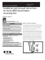
Seven pieces of mounting hardware are provided to mount
the pair of mounting feet (five M5 x 12 mounting screws, one
M5 x 25 mounting bolt, and one M5 nut). The M5 x 25 bolt,
and M5 nut are used with the right side mounting foot only to
ground (earth) the mounting foot to the breaker mechanism.
One mounting hole and one slot are provided in each mount-
ing foot for attaching the circuit breaker to an appropriate
horizontal mounting surface. Two mounting slots are provided
in each mounting foot for attaching the circuit breaker to an
appropriate vertical mounting surface. M8 or 5/16-inch mount-
ing hardware is recommended for mounting the breaker, and
is provided by the customer (Figure 1).
Figure 1. Right Side Mounting Foot
Instructions apply to:
1600 NRX SUB-TITLE IMAGE (12/15/2010)
Series NRX, Type NF Frame
ANSI, UL1066, UL489/IEC, IZMX16, IZM91

2
EATON CORPORATION www.eaton.com
Instructional Leaet IL01301030E
Effective December 2010
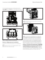
To assist with determining exact mounting requirements,
refer to Figure 2 and Figure 3 for mounting foot dimensional
information.
Figure 2. Front View—Dimensions in Inches (mm)
Figure 3. Top View—Dimensions in Inches (mm)
Section 2: Mounting feet installation
To install the mounting feet, proceed with the following six
steps:
Step 1: Remove the four screws holding the front cover in
place (two on each side of the cover).
Figure 4. Step 1
Step 2: Remove the front cover. Pull down on the charging
handle to simplify removal.
Figure 5. Step 2
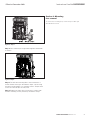
Step 3: Line up the three mounting holes in the right side
mounting foot with the mounting holes in the right side of
the circuit breaker. Use two M5 x 12 screws, one M5 x 25
mounting bolt, and one M5 nut of the mounting hardware
provided to attach the right side mounting foot to the right
side of the breaker. The M5 x 25 mounting bolt and M5 nut
are used in the lower front mounting hole, and provide for a
grounding (earthing) connection to the breaker mechanism.
The M5 x 25 bolt goes through the side of the breaker hous-
ing and is secured from the inside by the M5 nut. Grounding
(earthing) is not required for UL 489 product only. The M5
x 25 bolt with M5 nut are still used on UL 489 product to
attach the mounting foot to the frame only. The two M5
x 12 screws are used in the upper mounting holes. Once all
mounting hardware is in place, complete the process by tight-
ening the mounting hardware to 5–6 ft-lbs (6.6–8.1 Nm).

3
EATON CORPORATION www.eaton.com
Effective December 2010
Instructional Leaet IL01301030E
Figure 6. Step 3
Step 4: Once mounted, the right mounting foot should look
as shown.
Figure 7. Step 4
Step 5: The left side mounting foot is then mounted in a
similar fashion to that just described in Steps 3 and 4 using
the three remaining M5 x 12 mounting screws. Torque these
screws to 5–6 ft-lbs (6.6–8.1 Nm) also.
Step 6: Replace the front cover and secure it in place with
the four mounting screws previously removed in Step 1.
Section 3: Mounting
feet removal
To remove the mounting feet, reverse the procedure just
described in Section 2.

Instructional Leaet IL01301030E
Effective December 2010
Disclaimer of warranties and limitation of liability
The information, recommendations, descriptions, and safety
notations in this document are based on Eaton Corporation’s
(“Eaton”) experience and judgment, and may not cover all contin-
gencies. If further information is required, an Eaton sales office
should be consulted.
Sale of the product shown in this literature is subject to the
terms and conditions outlined in appropriate Eaton selling poli-
cies or other contractual agreement between Eaton and the pur-
chaser.
THERE ARE NO UNDERSTANDINGS, AGREEMENTS,
WARRANTIES, EXPRESSED OR IMPLIED, INCLUDING
WARRANTIES OF FITNESS FOR A PARTICULAR PURPOSE OR
MERCHANTABILITY, OTHER THAN THOSE SPECIFICALLY SET
OUT IN ANY EXISTING CONTRACT BETWEEN THE PARTIES.
ANY SUCH CONTRACT STATES THE ENTIRE OBLIGATION OF
EATON. THE CONTENTS OF THIS DOCUMENT SHALL NOT
BECOME PART OF OR MODIFY ANY CONTRACT BETWEEN
THE PARTIES.
In no event will Eaton be responsible to the purchaser or user in
contract, in tort (including negligence), strict liability, or otherwise
for any special, indirect, incidental, or consequential damage or
loss whatsoever, including but not limited to damage or loss of
use of equipment, plant or power system, cost of capital, loss of
power, additional expenses in the use of existing power facilities,
or claims against the purchaser or user by its customers resulting
from the use of the information, recommendations, and descrip-
tions contained herein.
The information contained in this manual is subject to change
without notice.
Eaton Corporation
Electrical Group
1000 Cherrington Parkway
Moon Township, PA 15108
United States
877-ETN-CARE (877-386-2273)
Eaton.com
© 2010 Eaton Corporation
All Rights Reserved
Printed in USA
Publication No. IL01301030E
December 2010

Gültig ab Dezember 2010
Ersetzt Juni 2010
IL01301030EH03
Montageanweisung IL01301030E
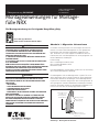
Montageanweisungen für Montage-
füße NRX
WARNUNG
(1) DIE INSTANDHALTUNG DARF NUR DURCH ENTSPRECHEND
ELEKTRONTECHNISCH QUALIFIZIERTES PERSONAL ERFOLGEN.
(2) VOR BEGINN DER ARBEITEN MUSS DER SPANNUNGSFREIE
ZUSTAND DER SCHALTANLAGE HERGESTELLT UND WÄHREND DER
ARBEITEN SICHERGESTELLT SEIN.
(3) SCHALTER IN AUSFAHRTECHNIK MÜSSEN IN TRENNSTELLUNG
GEFAHREN WERDEN.
(4) DIE SCHALTER SIND AUF AUS ZU STELLEN UND DER FEDERSPEICHER
IST ZU ENTSPANNEN.
BEIM BETRIEB ELEKTRISCHER GERÄTE STEHEN ZWANGSLÄUFIG
BESTIMMTE TEILE DIESER GERÄTE UNTER GEFÄHRLICHER SPANNUNG.
UNSACHGEMÄSSER UMGANG MIT DIESEN GERÄTEN KANN
DESHALB ZU TOD ODER SCHWEREN KÖRPERVERLETZUNGEN SOWIE
ERHEBLICHEN SACHSCHÄDEN FÜHREN.
WARNUNG
BEACHTEN SIE BEI INSTANDHALTUNGSMASSNAHMEN AN DIESEM
GERÄT ALLE IN DIESER AWA UND AUF DEM PRODUKT SELBST
AUFGEFÜHRTEN HINWEISE. DIE FÜNF SICHERHEITSREGELN SIND
EINZUHALTEN:
– FREISCHALTEN
– GEGEN WIEDEREINSCHALTEN SICHERN
– SPANNUNGSFREIHEIT FESTSTELLEN
– ERDEN UND KURZSCHLIESSEN
– BENACHBARTE, UNTER SPANNUNG STEHENDE TEILE ABDECKEN
ODER ABSCHRANKEN
DAS GERÄT IST VOM NETZ ZU TRENNEN. ES DÜRFEN NUR VOM
HERSTELLER ZUGELASSENE ERSATZTEILE VERWENDET WERDEN.
DIE VORGESCHRIEBENEN WARTUNGSINTERVALLE SOWIE DIE
ANWEISUNGEN FÜR REPARATUR UND AUSTAUSCH SIND UNBEDINGT
EINZUHALTEN, UM SCHÄDEN AN PERSONEN UND ANLAGEN ZU
VERMEIDEN.
Abschnitt 1: Allgemeine Informationen
Festeinbau-Leistungsschalter mit rückseitigen Anschlüssen
können mit einem Paar Montagefüße an einer geeigneten
horizontalen oder vertikalen Oberäche angebracht wer-
den. Zusätzlich ist es auch möglich Festeinbauschalter mit
Frontanschlüssen mit Montagefüßen an einer geeigneten ver-
tikalen Oberäche anzubringen.
Lieferumfang:
M5 x 12 Montageschrauben (fünf)
M5 x 25 Montagebolzen (einer)
M5 Mutter (eine)
Der Montagebolzen und die Mutter werden nur für die Erdung
des rechten Montagefußes benötigt.
Ein Montageloch und ein Montageschlitz in jedem Fuß sind
dafür vorgesehen den Leistungsschalter an einer geeigneten
horizontalen Oberäche anzubringen. Zwei Montageschlitze
in jedem Fuß sind dafür vorgesehen den Leistungsschalter an
einer geeigneten vertikalen Oberäche anzubringen. M8 bzw.
5/16-inch Schrauben werden für die Montage empfohlen und
müssen vom Kunden zur Verfügung gestellt werden.
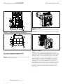
Abbildung 1 - Montagefuß Rechte Seite
Montagebohrung
für M5 x 25
Montagebolzen
und M5 Mutter
Montageschlitze
für vertikale
Anbringung
Montagebohrung und
Montageschlitz für horizontale
Anbringung
Die Montageanweisung ist für folgende Baugrößen gültig:
1600 NRX SUB-TITLE IMAGE (12/15/2010)
Series NRX, Type NF Frame
ANSI, UL1066, UL489/IEC, IZMX16, IZM91

2
EATON CORPORATION www.eaton.com
Montageanweisung IL01301030E
Gültig ab Dezember 2010
Abbildung 2 - Frontansicht - Abmessungen in Zoll (mm)
Abbildung 3 - Draufsicht - Abmessungen in Zoll (mm)
Abschnitt 2: Einbau der Montagefüße
Führen Sie die folgenden Schritte aus:
Schritt 1: Entfernen Sie die vier Schrauben von der Fontab-
deckung (zwei an jeder Seite).
,
,
,
,
,
,
,
,
,
,
,
Abbildung 4 - Schritt 1
Schritt 2: Entfernen Sie die Frontabdeckung, ziehen Sie dabei
den Handhebel herunter, um die Abdeckung leichter entfernen
zu können.
Abbildung 5 - Schritt 2
Schritt 3: Legen Sie den rechten Montagefuß so an den
Schalter an, dass die Befestigungsbohrungen des Fußes über
den Aufnahmebohrungen am Schaltergehäuse liegen. Für die
Montage werden zwei der beiliegenden M5x12 Schrauben,
einer der beiliegenden M5x25 Montagebolzen und eine M5
Mutter benötigt. Der M5x25 Montagebolzen und die M5
Mutter werden in die fordere, untere Befestigungsbohrung
eingebaut, um den Schaltermechanismus zu erden. Der
Montagebolzen wird durch die Seite des Gehäuses eingeführt
und von der Mutter von innen gesichert. Die beiden M5x12
Schrauben werden in die oberen Befestigungsbohrungen
eingebaut. Ziehen Sie alle Schrauben und Muttern an (M
A
=
6,6 - 8,1 Nm)

3
EATON CORPORATION www.eaton.com
Gültig ab Dezember 2010
Montageanweisung IL01301030E
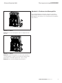
Abbildung 6 - Schritt 3
Schritt 4: Der rechte Montagefuß sollte wie dargestellt mon-
tiert sein.
Abbildung 7 - Schritt 4
Schritt 5: Die linke Montagefuß wird, wie in den Schritten 3
und 4 beschrieben, montiert. Dazu werden die übrigen beilie-
genden M5x12 Schrauben genutzt (M
A
= 6,6 - 8,1 Nm).
Schritt 6: Bauen Sie die Frontabdeckung wieder an.
M5 Mutter M5 x 25 Montagebolzen
hier einsetzen
Abschnitt 3: Entfernen der Montagefüße
Um die Montagefüße zu entfernen, nehmen Sie die Front-
abdeckung ab, entfernen Sie die Schrauben, nehmen Sie die
Montagefüße ab und bauen Sie anschließend die Frontabdeck-
ung wieder an.

Montageanweisung IL01301030E
Gültig ab Dezember 2010
Eaton Corporation
Electrical Group
1000 Cherrington Parkway
Moon Township, PA 15108
United States
877-ETN-CARE (877-386-2273)
Eaton.com
© 2010 Eaton Corporation
All Rights Reserved
Printed in USA
Publication No. IL01301030E
Dezember 2010
PowerChain Management is a registered
trademark of Eaton Corporation.
All other trademarks are property of their
respective owners.
-
 1
1
-
 2
2
-
 3
3
-
 4
4
-
 5
5
-
 6
6
-
 7
7
-
 8
8


in anderen Sprachen
- English: Eaton NRX Series
Verwandte Artikel
-
Eaton Series NRX Installation Instructions Manual
-
Eaton NRX Series Instruction Leaflet
-
-
-
-
-
-
-
-