
Installation and Removal Instructions
for Series NRX Cassette Cell Switch
• WARNING
(1) ONLY QUALIFIED ELECTRICAL PERSONNEL SHOULD BE PERMITTED TO WORK
ON THE EQUIPMENT.
(2) ALWAYS DE-ENERGIZE PRIMARY AND SECONDARY CIRCUITS IF A CIRCUIT
BREAKER CANNOT BE REMOVED TO A SAFE WORK LOCATION.
(3) DRAWOUT CIRCUIT BREAKERS SHOULD BE LEVERED (RACKED) OUT TO THE
DISCONNECT POSITION.
(4) ALL CIRCUIT BREAKERS SHOULD BE SWITCHED TO THE OFF POSITION AND
MECHANISM SPRINGS DISCHARGED.
FAILURE TO FOLLOW THESE STEPS FOR ALL PROCEDURES DESCRIBED IN THIS
INSTRUCTION LEAFLET COULD RESULT IN DEATH, BODILY INJURY, OR PROPERTY
DAMAGE.
• WARNING
THE INSTRUCTIONS CONTAINED IN THIS IL AND ON PRODUCT LABELS HAVE TO
BE FOLLOWED. OBSERVE THE FIVE SAFETY RULES:
– DISCONNECTING
– ENSURE THAT DEVICES CANNOT BE ACCIDENTALLY RESTARTED
– VERIFY ISOLATION FROM THE SUPPLY
– EARTHING AND SHORT-CIRCUITING
– COVERING OR PROVIDING BARRIERS TO
ADJACENT LIVE PARTS
DISCONNECT THE EQUIPMENT FROM THE SUPPLY. USE ONLY AUTHORIZED
SPARE PARTS IN THE REPAIR OF THE EQUIPMENT. THE SPECIFIED MAINTENANCE
INTERVALS AS WELL AS THE INSTRUCTIONS FOR REPAIR AND EXCHANGE MUST
BE STRICTLY ADHERED TO PREVENT INJURY TO PERSONNEL AND DAMAGE TO
THE SWITCHBOARD.
Effective April 2014
Supercedes August 2013 Series NRXInstruction Leaet IL01301054E
Series NRX, Type RF Frame
IEC, IZMX40
4000 NRX RF DRAWOUT SUBTITLE IMAGE (12/15/2010)
Instructions apply to:

2
Installation and Removal Instructions
for Series NRX Cassette Cell Switch
EATON www.eaton.com
Instruction Leaet IL01301054E
Effective April 2014
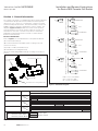
Section 1: General Information
The cassette cell switch is a compartment position switch for drawout
circuit breakers that provides remote indication of breaker position
(disconnect, test, connect). It is comprised of a cassette mounted
switch assembly and an actuator. The switch assembly consists of 3
FORM C switches, which are operated by a common actuator. The
diagrams (Figures 2 and 3) illustrate the switch contact positions
when the breaker is in a specific position within the cassette. As
the breaker is levered in or out from one position to another the
appropriate switch changes state as a result of contact with the
breaker mounted actuator.
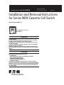
Kit Parts Identification
Refer to Figure 1 for visual identification of the parts listed below:
(A) Cell switch assembly (1)
(B) Cell switch actuator (1) and M3 x 5mm mounting screws (2)
(screws not shown)
(C) (Fixed) secondary terminal blocks (5)
(D) Terminal block mounting bracket (1)
(E) 12mm self-threading TORX head type mounting screws (3) (not
shown)
Figure 1. Contents of Kit
Figure 2.
Signaling switch for: Contacts Circuit-breaker position
Disconnect Position Test Position Connected Position
Disconnect Position
Test Position
Connected Position
COM - Common Wire (BLACK) Contact Open
NO - Normally Open (RED)
Contact Closed
NC - Normally Closed (BLUE)
COM
NC
NO
COM
NC
NO
COM
NC
NO
Circuit Breaker Position and Contacts
Cell switch assembly (A)
Actuator (B)
Terminal block mounting bracket (D)
Secondary terminal
block (C)
Figure 3.
COM - common wire (BLACK)
NO - normally open (RED)
NC - normally closed (BLUE)
Breaker in Connected Position
COM
NC
NO
CONNECTED
NO
NC
TEST
DISCONNECT
CONNECTED
TEST
DISCONNECT
CONNECTED
TEST
DISCONNECT
Breaker in Test PositionBreaker in Disconnected Position
COMCOMCOMCOMCOMCOMCOMCOM
NO
NC
NO
NC
NO
NC
NO
NC
NO
NC
NC
NO
NC
NO
C1
C2
C3
D1
D2
D3
T1
T2
T3
Cell Switch Diagrams

3
Instruction Leaet IL01301054E
Effective April 2014
Installation and Removal Instructions
for Series NRX Cassette Cell Switch
EATON www.eaton.com
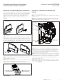
Section 3: Installation of Cassette Cell
Switch
Proceed with the following 5 steps.
Note: The circuit breaker must be removed from its cassette prior to starting the
installation process.
Step 1: The cell switch assembly (A) is mounted on the inside of the
cassette’s side sheet. Three screws are used to mount the assembly
and they are supplied with the cell switch kit.
Figure 7.
Secondary
terminal blocks
mounted to arc
hood
Top mounting
hole
Mounting
holes
DIN rail
Inside of cassette
left side sheet
Steps 1-3
Step 2: Position the cell switch assembly (A) on the inside of the
cassette’s side sheet so the three mounting holes match up with the
switch assembly mounting holes. Confirm the arrow at the top of
the cell switch cases are pointing up and the arrow on the actuator is
pointing toward the front of the cassette.
Step 3: Insert the 12mm TORX head type mounting screw (E) supplied
with the kit into the top mounting hole first. Next insert the remaining
12mm TORX head type mounting screws. Hand tighten to a maximum
torque of 25 in. lbs. (2.8 Nm). Move the actuator front to back to
ensure that the slider is free.
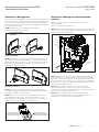
Step 4: The terminal block mounting bracket (D) can be mounted on
the secondary DIN rail next to the secondary terminal blocks mounted
to the arc hood. (Figure 7).
Section 2: Cell Switch Actuator Orientation
The cell switch assembly is mounted to the inside of the cassette side
sheet on either the left or right side. The kit comes preassembled for
installation to the left side of the cassette. If mounting to the right
side sheet is preferred the actuator can be changed as follows.
Step 1: Remove the two M3 screw and the actuator from the
assembly.
Figure 4.
LEFT SIDE MOUNTING
(DEFAULT)
RIGHT SIDE MOUNTING
SECTION 2-STEP 1 IMAGE
SECTION 2-STEP 2 IMAGE
ACTUATOR
ARROW
M3 SCREWS
ACTUATOR
Step 1
Step 2: Move the actuator to the opposite side of the assembly and
ensure that the arrow molded on the actuator is pointing to the shorter
side of the cases, this is the front. Reinstall the screw closest to the
arrow first, followed by the one at the end of the lever. Fully seat the
screws. Do not over tighten.
Figure 5.
LEFT SIDE MOUNTING
(DEFAULT)
RIGHT SIDE MOUNTING
SECTION 2-STEP 1 IMAGE
SECTION 2-STEP 2 IMAGE
ACTUATOR
ARROW
M3 SCREWS
ACTUATOR
Step 2
Step 3: Slowly slide the actuator through its full range to ensure free
motion and that it returns fully.
Step 4: Move the cell switch wires from the wire retention slot on the
left side of the terminal bracket over to the slot on the right side. This
helps keep the wires tight against the cassette side sheet
Figure 6.
ROUTE WIRES THROUGH
THIS RETENTION SLOT FOR
LEFT SIDE MOUNTING
ROUTE WIRES THROUGH
THIS RETENTION SLOT FOR
RIGHT SIDE MOUNTING
Step 4

4
Installation and Removal Instructions
for Series NRX Cassette Cell Switch
EATON www.eaton.com
Instruction Leaet IL01301054E
Effective April 2014
Figure 8. Step 4
Step 5: The circuit breaker can now be put back into the cassette.
Lever the breaker into and out of its three positions to ensure that cell
switch assembly is operating smoothly.
ote:N Keep in mind that the indicator on the front of the circuit breaker must
indicate that the breaker is in the DISCONNECT position to permit insertion of
the breaker into its cassette.
Wiring to the cell switch terminal block must be kept clear of the arc hood vents.
Section 4: Removal of Cassette Cell Switch
Remove the circuit breaker from its cassette and perform Steps 1
through 5 in reverse.
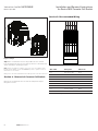
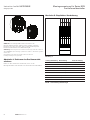
Section 5: Recommended Wiring
Figure 9.
Wire Label Description Wire Color
D1 Disconnect NO Red
D2 Disconnect COM Black
D3 Disconnect NC Blue
T1 Test NO Red
T2 Test COM Black
T3 Test NC Blue
C1 Connect NO Red
C2 Connect COM Black
C3 Connect NC Blue
Table 1. Secondary Terminal Points
D2
D3
T2
C2
C3
D1
T3
T1
C1

5
Instruction Leaet IL01301054E
Effective April 2014
Installation and Removal Instructions
for Series NRX Cassette Cell Switch
EATON www.eaton.com
Notes:

6
Installation and Removal Instructions
for Series NRX Cassette Cell Switch
EATON www.eaton.com
Instruction Leaet IL01301054E
Effective April 2014
Eaton is a registered Trademark.
All other Trademarks are property of their
respective owners.
Eaton
1000 Eaton Boulevard
Cleveland OH, 44122
United States
877-ETN-CARE (877-386-2273)
Eaton.com
© 2014 Eaton
All Rights Reserved
Printed in USA
Publication No. IL01301054EH03 / TBG0001100
April 2014
Disclaimer of warranties and limitation of liability
The information, recommendations, descriptions, and safety
notations in this document are based on Eaton Corporation’s
(“Eaton”) experience and judgment, and may not cover all
contingencies. If further information is required, an Eaton sales
office should be consulted.
Sale of the product shown in this literature is subject to the terms
and conditions outlined in appropriate Eaton selling policies or
other contractual agreement between Eaton and the purchaser.
THERE ARE NO UNDERSTANDINGS, AGREEMENTS,
WARRANTIES, EXPRESSED OR IMPLIED, INCLUDING
WARRANTIES OF FITNESS FOR A PARTICULAR PURPOSE OR
MERCHANTABILITY, OTHER THAN THOSE SPECIFICALLY SET
OUT IN ANY EXISTING CONTRACT BETWEEN THE PARTIES. ANY
SUCH CONTRACT STATES THE ENTIRE OBLIGATION OF EATON.
THE CONTENTS OF THIS DOCUMENT SHALL NOT BECOME
PART OF OR MODIFY ANY CONTRACT BETWEEN THE PARTIES.
In no event will Eaton be responsible to the purchaser or user in
contract, in tort (including negligence), strict liability, or otherwise
for any special, indirect, incidental, or consequential damage
or loss whatsoever, including but not limited to damage or loss
of use of equipment, plant or power system, cost of capital,
loss of power, additional expenses in the use of existing power
facilities, or claims against the purchaser or user by its customers
resulting from the use of the information, recommendations, and
descriptions contained herein.
The information contained in this manual is subject to change
without notice.

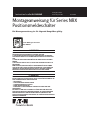
Montageanweisung für Series NRX
Positionsmeldeschalter
n WARNUNG
(1) DIE INSTANDHALTUNG DARF NUR DURCH ENTSPRECHEND
ELEKTRONTECHNISCH QUALIFIZIERTES PERSONAL ERFOLGEN.
(2) VOR BEGINN DER ARBEITEN MUSS DER SPANNUNGSFREIE ZUSTAND DER
SCHALTANLAGE HERGESTELLT UND WÄHREND DER ARBEITEN SICHERGESTELLT
SEIN.
(3) SCHALTER IN AUSFAHRTECHNIK MÜSSEN IN TRENNSTELLUNG GEFAHREN
WERDEN.
(4) DIE SCHALTER SIND AUF AUS ZU STELLEN UND DER FEDERSPEICHER IST ZU
ENTSPANNEN.
BEIM BETRIEB ELEKTRISCHER GERÄTE STEHEN ZWANGSLÄUFIG BESTIMMTE
TEILE DIESER GERÄTE UNTER GEFÄHRLICHER SPANNUNG. UNSACHGEMÄSSER
UMGANG MIT DIESEN GERÄTEN KANN DESHALB ZU TOD ODER SCHWEREN
KÖRPERVERLETZUNGEN SOWIE ERHEBLICHEN SACHSCHÄDEN FÜHREN.
n WARNUNG
BEACHTEN SIE BEI INSTANDHALTUNGSMASSNAHMEN AN DIESEM GERÄT ALLE
IN DIESER AWA UND AUF DEM PRODUKT SELBST AUFGEFÜHRTEN HINWEISE. DIE
FÜNF SICHERHEITSREGELN SIND EINZUHALTEN
– FREISCHALTEN
– GEGEN WIEDEREINSCHALTEN SICHERN
– SPANNUNGSFREIHEIT FESTSTELLEN
– ERDEN UND KURZSCHLIESSEN
– BENACHBARTE, UNTER SPANNUNG STEHENDE TEILE ABDECKEN ODER
ABSCHRANKEN
DAS GERÄT IST VOM NETZ ZU TRENNEN. ES DÜRFEN NUR VOM HERSTELLER
ZUGELASSENE ERSATZTEILE VERWENDET WERDEN. DIE VORGESCHRIEBENEN
WARTUNGSINTERVALLE SOWIE DIE ANWEISUNGEN FÜR REPARATUR UND
AUSTAUSCH SIND UNBEDINGT EINZUHALTEN, UM SCHÄDEN AN PERSONEN UND
ANLAGEN ZU VERMEIDEN.
Gültig April 2014
Ersetz August 2013 Serie NRXInstruction Leaet IL01301054E
Series NRX, Type RF Frame
IEC, IZMX40
4000 NRX RF DRAWOUT SUBTITLE IMAGE (12/15/2010)
Die Montageanweisung ist für folgende Baugrößen gültig:

2
Montageanweisung für Series NRX
Positionsmeldeschalter
EATON www.eaton.com
Instruction Leaet IL01301054E
Gültig April 2014
Abschnitt 1: Allgemeine Informationen
Jeder Positionsmeldeschalter besteht aus drei einpoligen
Wechselschaltern welche von einem einfachen Auslöser betätigt
werden. Abbildung 2 und 3 zeigen die Position der Kontakte in der
jeweiligen Position des Schalters in der Kassette.
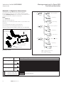
Inhalt
siehe Abbildung 1
(A) Positionsmeldeschalter (1)
(B) Auslöser (1) und Montageschrauben M3 x 5 (2) (Schrauben nicht
abgebildet)
(C) Steuerleitungsanschlussblöcke (Festeinbau) (5)
(D) Halterung für Steuerleitungsanschlussblöcke (1)
(E) 12mm selbstschneidende TORX Schrauben (3) (nicht abgebildet)
Abbildung 1.
Positionsmeldeschalter (A)
und Torx Schrauben (E)
Auslöser (B) mit M3
Montageschrauben
Halterung (D)
Steuerleitungs-
anschlussblock (C)
Inhalt
Abbildung 3.
COM - common wire (schwarz)
NO - normally open (rot)
NC - normally closed (blau)
Schalter eingefahren
COM
NC
NO
Schalter eingefahren
NO
NC
Teststellung
Trennstellung
Schalter eingefahren
Teststellung
Trennstellung
Schalter eingefahren
Teststellung
Trennstellung
Schalter in TeststellungSchalter in Trennstellung
COMCOMCOMCOMCOMCOMCOMCOM
NO
NC
NO
NC
NO
NC
NO
NC
NO
NC
NC
NO
NC
NO
C1
C2
C3
D1
D2
D3
T1
T2
T3
Kontakte Positionsmeldeschalter
Abbildung 2.
Signalisierung für: Kontakte Stellung Leistungsschalter
Trennstellung Teststellung Schalter eingefahren
Trennstellung
Teststellung
Schalter eingefahren
COM - Common Wire (schwarz) Kontakt offen
NO - Normally Open (rot)
Kontakt geschlossen
NC - Normally Closed (blau)
COM
NC
NO
COM
NC
NO
COM
NC
NO
Zustand Kontakte bei jeweiliger Leistungsschalterstellung

3
Instruction Leaet IL01301054E
Gültig April 2014
Montageanweisung für Series NRX
Positionsmeldeschalter
EATON www.eaton.com
Abschnitt 3: Montage des Positionsmelde-
schalters
Enfternen Sie den Schalter aus der Kassette bevor Sie mit der
Montage beginnen.
Führen Sie die folgenden Schritte aus:
Schritt 1: Der Positionsmeldeschalter (A) wird an der linken Innenwand
der Kassette montiert. Dafür werden drei Schrauben benötigt. Diese
sind Bestandteil des Montagesatzes.
Abbildung 7.
Steuerleitungsanschlüsse
obere
Aufnahme-
bohrung
Aufnahme-
bohrungen
linke Kassetten-
innenseite
Schritts 1-3
Schritt 2: Positionieren Sie die Positionsmeldeschalter-Einheit (A) so
auf der Innenseite des Seitenblechs der Kassette, dass sich die drei
Bohrungen mit den Montagelöchern der Positionsmeldeschalter-Einheit
decken. Prüfen Sie, dass der Pfeil oben auf der Positionsmeldeschalter-
Einheit nach oben zeigt, und der Pfeil auf der Betätigungsvorrichtung
zur Vorderseite der Kassette zeigt.
Schritt 3: Schrauben Sie zuerst eine Torx Schraube (E) in die
obere Aufnahmebohrung. Hand ziehen sie mit einem maximalen
Drehmoment von 25 in-lbs. (2,8 Nm). Bewegen Sie den bremszylinder
vorne nach hinten, damit der Regler ist frei.
Schritt 4: Die Montagehalterung für die Reihenklemmen (D)
kann auf die zweite DIN-Schiene neben den bereits vorhandenen
Reihenklemmen aufgesteckt werden. (Abbildung 7).
Abschnitt 2: Montageseite
Die Positionsmeldeschalter-Einheit kann in der Kassette entweder rechts
oder links am inneren Seitenblech montiert werden. Der Bausatz wird
vormontiert für den linksseitigen Einbau geliefert. Wenn die Montage
auf der rechten Seite bevorzugt wird, kann die Betätigungsvorrichtung
wie folgt verändert werden:
Schritt 1: Entfernen Sie die zwei M3-Schrauben und die
Betätigungsvorrichtung von der Einheit.
Abbildung 4.
LINKSSEITIGER EINBAU
(STANDARD)
RECHTSSEITIGER EINBAU
SECTION 2-STEP 1 IMAGE
SECTION 2-STEP 2 IMAGE
PFEIL DER
BETÄTIGUNGSVORRICHTUNG
M3-SCHRAUBEN
BETÄTIGUNGS-
VORRICHTUNG
Schritt 1
Schritt 2: Montieren Sie die Betätigungsvorrichtung der Einheit auf
die gegenüberliegende Seite und stellen Sie sicher, dass der Pfeil der
Betätigungsvorrichtung zur kürzeren Seite des Gehäuses zeigt. Bringen
Sie die näher am Pfeil befindliche Schraube zuerst wieder an, und
danach die am Ende des Hebels.
Abbildung 5.
LINKSSEITIGER EINBAU
(STANDARD)
RECHTSSEITIGER EINBAU
SECTION 2-STEP 1 IMAGE
SECTION 2-STEP 2 IMAGE
PFEIL DER
BETÄTIGUNGSVORRICHTUNG
M3-SCHRAUBEN
BETÄTIGUNGS-
VORRICHTUNG
Schritt 2
Schritt 3: Schieben Sie die Betätigungsvorrichtung langsam durch
ihren ganzen Bewegungsbereich, um die freie Beweglichkeit und das
selbständige rückfahren sicherzustellen.
Schritt 4: Stecken Sie die Drähte des Positionsmeldeschalters von
der Aussparung auf der linken Seite der Anschlussklemme in die
gegenüberliegende Aussparung auf der rechten Seite. So werden die
Drähte eng an der Seite der Kassette entlang geführt.
Abbildung 6. Schritt 4
STECKEN SIE DIE DRÄHTE
DURCH DIE AUSSPARUNG FÜR
DIE LINKSSEITIGE MONTAGE
STECKEN SIE DIE DRÄHTE
DURCH DIE AUSSPARUNG FÜR
DIE RECHTSSEITIGE MONTAGE
DIN-
Schiene

4
Montageanweisung für Series NRX
Positionsmeldeschalter
EATON www.eaton.com
Instruction Leaet IL01301054E
Gültig April 2014
Abschnitt 5: Empfohlene Verdrahtung
Abbildung 9.
D2
D3
T2
C2
C3
D1
T3
T1
C1
Leitungsmarkierung Beschreibung Farbe der Leitung
D1 Trennstellung NO Rot
D2 Trennstellung COM Schwarz
D3 Trennstellung NC Blau
T1 Teststellung NO Rot
T2 Teststellung COM Schwarz
T3 Teststellung NC Blau
C1 Eingefahren NO Rot
C2 Eingefahren COM Schwarz
C3 Eingefahren NC Blau
Tabelle 1. Steuerleitungsmarkierungen
Abbildung 8. Schritt 4
Schritt 5: Der Leistungsschalter kann nun wieder in die
Kassette gefahren werden. Fahren Sie den Schalter in alle drei
Positionen, um sicher zu stellen, dass es nach der Montage des
Positionsmeldeschalters keine Widerstände gibt.
Anmerkung: Die Anzeige auf dem Schalter muss anzeigen, dass der Schalter in
der DISCONNECT (Trennstellung) ist, damit der Schalter in die Kassette gefahren
werden kann.
Die Verdrahtung zum Reihenklemmblock darf nicht über den
Lichtbogenöffnungen verlegt werden.
Abschnitt 4: Entfernen des Positionsmelde-
schalters
Fahren Sie den Schalter aus der Kassette, lösen Sie die
Montageschrauben und entnehmen Sie den Positionsmeldeschalter.

5
Instruction Leaet IL01301054E
Gültig April 2014
Montageanweisung für Series NRX
Positionsmeldeschalter
EATON www.eaton.com

6
Montageanweisung für Series NRX
Positionsmeldeschalter
EATON www.eaton.com
Instruction Leaet IL01301054E
Gültig April 2014
Eaton is a registered Trademark
All other Trademarks are property of their
respective owners.
Eaton
Electrical Group
1000 Eaton Boulevard
Cleveland, OH44122
United States
877-ETN-CARE (877-386-2273)
Eaton.com
© 2014 Eaton
All Rights Reserved
Printed in USA
Publication No. IL01301054EH03
April 2014
Die Angaben, Empfehlungen, Beschreibungen und Sicherheitshinweise
in diesem Dokument basieren auf Erfahrungswerten und
Einschätzungen von Eaton Corporation („Eaton“) und decken nicht alle
Möglichkeiten ab. Wenn weitere Informationen benötigt werden, sollte
ein Vertriebsbüro von Eaton kontaktiert werden.
Der Verkauf des in diesem Dokument beschriebenen
Produktes unterliegt den Bedingungen in den entsprechenden
Geschäftsbedingungen von Eaton oder anderen vertraglichen
Vereinbarungen zwischen Eaton und dem Käufer.
ES GIBT KEINE ABSPRACHEN, VEREINBARUNGEN,
GEWÄHRLEISTUNGEN, WEDER EXPLIZIT NOCH IMPLIZIT,
EINSCHLIESSLICH DER GEWÄHRLEISTUNG DER
EIGNUNG FÜR EINEN BESTIMMTEN ZWECK ODER DER
GEBRAUCHSTAUGLICHKEIT, MIT AUSNAHME DER IN
BESTEHENDEN VERTRÄGEN ZWISCHEN DEN PARTEIEN SPEZIELL
VEREINBARTEN. JEDER DERARTIGE VERTRAG STELLT DIE
GESAMTEN PFLICHTEN VON EATON DAR. DER INHALT DIESES
DOKUMENTS IST NICHT TEIL EINES VERTRAGS ZWISCHEN DEN
PARTEIEN UND VERÄNDERT AUCH KEINEN SOLCHEN.
Eaton kann in keinem Fall gegenüber dem Käufer oder dem Benutzer
haftbar gemacht werden, ob aufgrund eines Vertrages, unerlaubter
Handlung (einschließlich Fahrlässigkeit), verschuldensunabhängig oder
einer anderen Anspruchsgrundlage, für spezielle, indirekte, gleichzeitige
oder Folgeschäden oder -verluste gleich welcher Art, einschließlich
unter anderem Schäden oder Verluste von Geräten, Anlagen,
Kapitalkosten, Leistungsverluste, zusätzliche Auslagen bei der Nutzung
der vorhandenen Einrichtungen oder Ansprüchen, die Kunden infolge
der Nutzung der Informationen, Empfehlungen und Beschriftungen in
diesem Dokument gegenüber dem Käufer oder dem Benutzer geltend
machen.
Die Angaben in dieser Gebrauchsanweisung können ohne
Vorankündigung geändert werden.
Haftungsausschluss und Haftungsbeschränkungen
-
 1
1
-
 2
2
-
 3
3
-
 4
4
-
 5
5
-
 6
6
-
 7
7
-
 8
8
-
 9
9
-
 10
10
-
 11
11
-
 12
12


in anderen Sprachen
- English: Eaton Series NRX
Verwandte Artikel
-
Eaton IL0131097EN Bedienungsanleitung
-
-
Eaton IL01301037E: Series NRX Bedienungsanleitung
-
-
-
-
-
-
-