
Effective December 2010
Supersedes October 2010
IL01301037EH04
Instructional Leaet IL01301037E
Installation/removal instructions
for Series NRX fixed and drawout
secondary terminal blocks
WARNING
(1) ONLY QUALIFIED ELECTRICAL PERSONNEL SHOULD BE PERMITTED TO
WORK ON THE EQUIPMENT.
(2) ALWAYS DE-ENERGIZE PRIMARY AND SECONDARY CIRCUITS IF A
CIRCUIT BREAKER CANNOT BE REMOVED TO A SAFE WORK LOCATION.
(3) DRAWOUT CIRCUIT BREAKERS SHOULD BE LEVERED (RACKED) OUT TO
THE DISCONNECT POSITION.
(4) ALL CIRCUIT BREAKERS SHOULD BE SWITCHED TO THE OFF POSITION
AND MECHANISM SPRINGS DISCHARGED. FAILURE
TO FOLLOW THESE
STEPS FOR ALL PROCEDURES
DESCRIBED IN THIS INSTRUCTION LEAFLET
COULD RESULT IN DEATH, BODILY INJURY, OR PROPERTY DAMAGE.
WARNING
THE INSTRUCTIONS CONTAINED IN THIS IL AND ON PRODUCT LABELS
HAVE TO BE FOLLOWED. OBSERVE THE FIVE SAFETY RULES:
– DISCONNECTING
– ENSURE THAT DEVICES CANNOT BE
ACCIDENTALLY RESTARTED
– VERIFY ISOLATION FROM THE SUPPLY
– EARTHING AND SHORT-CIRCUITING
– COVERING OR PROVIDING BARRIERS TO
ADJACENT LIVE PARTS
DISCONNECT THE EQUIPMENT FROM THE SUPPLY. USE ONLY
AUTHORIZED SPARE PARTS IN THE REPAIR OF THE EQUIPMENT. THE
SPECIFIED MAINTENANCE INTERVALS AS WELL AS THE INSTRUCTIONS
FOR REPAIR
AND EXCHANGE MUST BE STRICTLY ADHERED TO PREVENT
INJURY TO PERSONNEL AND DAMAGE TO THE SWITCHBOARD.
Section 1: General information
A maximum of 27 terminal blocks providing 54 secondary
contact points are available in one cradle on the NF Frame
circuit breaker. The RF Frame circuit breaker is available with
a maximum of 46 terminal blocks providing 92 secondary
contact points in two individual cradles. The number of termi-
nal blocks mounted depends on a number of considerations,
such as whether the circuit breaker is electrically or manually
operated and how many features are required. For example,
the shunt trip device has two leads and uses a single termi-
nal block. Other devices, such as a motor operator, has three
leads and requires two terminal blocks. Each connection point
is permanently identified. Terminal blocks can be individually
mounted and hence contact positions may be empty.
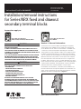
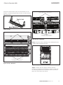
For drawout circuit breakers, secondary terminal blocks are
DIN rail mounted on the top front portion of the drawout cas-
sette. A cross connector can be used to tie adjacent contacts
together for drawout configurations (Figure 1).
Figure 1. Drawout Terminal Block
Instructions apply to:
1600 NRX SUB-TITLE IMAGE (12/15/2010)
Series NRX, Type NF Frame
ANSI, UL1066, UL489/IEC, IZMX16, IZM91
Series NRX, Type RF Frame
IEC, IZMX40
4000 NRX RF DRAWOUT SUBTITLE IMAGE (12/15/2010)

2
EATON CORPORATION www.eaton.com
Instructional Leaet IL01301037E
Effective December 2010
For fixed-mounted circuit breakers, secondary terminal blocks
mount onto an insulated support frame (Figure 2).
Figure 2. Fixed Terminal Block
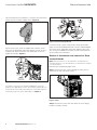
Electrical accessory leads are tagged with numbers associ-
ated with the applicable connection diagram. Leads are also
supplied with keyed secondary connector plugs to ensure
proper connections (Figure 3).
Figure 3. Leads and Connectors (Drawout Configuration Shown)
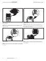
Secondary connections are made by plugging the connector
plugs into the appropriate location. A connector plug already con-
nected can be removed by squeezing two release tabs together
with small needle nose pliers and pulling out (Figure 4).
Figure 4. Connector Plug Removal
Customer wiring is done using tension clamp terminations.
Refer to manuals MN01301001E (NF Frame) or MN01301003E
(RF Frame) for an applicable connection diagram, other spe-
cific wiring, and additional secondary contact information for
all Series NRX circuit breakers.
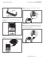
Section 2: Installation and removal of xed
terminal blocks
ote:N Many illustrations use the NF Frame circuit breaker for
illustrative purposes only. The RF Frame circuit breaker is handled
in a similar fashion.
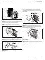
Proceed with the following eight steps:
Step 1: Remove the four screws holding the front cover in
place (two on each side of the cover).
Figure 5. Step 1
Step 2: Remove the front cover. Pull down on the charging
handle to simplify removal.

3
EATON CORPORATION www.eaton.com
Effective December 2010
Instructional Leaet IL01301037E
Figure 6. Step 2
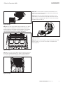
Step 3: Become familiar with the fixed terminal block DIN rail
type mounting plate where secondary connections
are made.
ote:N Secondary connection points have numerical and
descriptive laser-etched identifications.
Figure 7. Step 3
Step 4: Plug accessory connector plug into fixed secondary
terminal block.
Figure 8. Step 4
4
3
5
7
9
11
13
15
17
19
21
23
25
27
OT1M
OT2B
OT2M
ALM1
ALM2
ALMC
OT2C
OT1B
OT1C
N2
G2
G1
N1
SGF1
AGND
CMM2
CMM1
+24V
SGF2
CMM4
CMM3
ZOOM
ZOUT
UV2
UV1
6
8
10
12
14
16
18
20
22
24
26
28
30
32
34
9
11
13
15
17
19
21
23
25
27
OT2B
OT2M
ALM1
ALM2
ALMC
OT2C
OT1B
N2
G2
G1
N1
SGF1
AGND
CMM2
CMM1
+24V
SGF2
CMM3
8
10
12
14
16
18
20
22
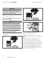
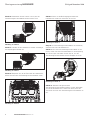
Step 5: Identify correct mounting location on fixed terminal
block mounting plate for mounting fixed secondary terminal
block. First insert the bottom end of the fixed secondary
terminal block into the proper location on the DIN rail type
mounting plate.
Figure 9. Step 5
Step 6: Rotate the top end of the terminal block in until it
engages the appropriate flexible mounting tab at the top of
the mounting plate with a clicking sound.
Figure 10. Step 6
Step 7: To remove a fixed secondary terminal block, lift up on
small flexible mounting tab at the top of fixed terminal block
mounting plate, and rotate the terminal block out in the oppo-
site direction shown in Step 6.
4
3
1
5
7
9
1
1
13
15
17
19
21
23
25
27
OT1M
OT2B
OT2M
ALM1
ALM2
ALMC
OT2C
OT1B
OT1C
N2
G2
G1
N1
SGF1
AGND
CMM2
CMM1
+24V
SGF2
CMM4
CMM3
ZOOM
ZOU
T
UV2
UV1
6
8
10
12
14
16
18
20
22
24
26
28
30
32
34
14
13

4
EATON CORPORATION www.eaton.com
Instructional Leaet IL01301037E
Effective December 2010
IMPORTANT
KEEP IN MIND THAT TO REMOVE AN ACCESSORY PLUG ON A FIXED
CIRCUIT BREAKER, THE APPROPRIATE FIXED SECONDARY TERMINAL
BLOCK MUST FIRST BE REMOVED. ONCE THE TERMINAL BLOCK IS
REMOVED, THE ACCESSORY CONNECTOR PLUG CAN BE UNPLUGGED
FROM THE BOTTOM OF THE TERMINAL BLOCK. REFER TO FIGURE 4 IN
SECTION 1 FOR ASSISTANCE WITH THE REMOVAL.
Step 8: Once all terminal blocks are securely mounted, replace
the front cover and secure it in place with the four mounting
screws previously removed in Step 1.
Section 3: Installation and removal of dra-
wout terminal blocks
IMPORTANT
KEEP IN MIND THAT SECONDARY TERMINAL BLOCKS ASSOCIATED
WITH DRAWOUT CIRCUIT BREAKERS ARE DIN RAIL MOUNTED ON
THE BREAKER’S DRAWOUT CASSETTE (FIGURE 11). ACCESSORY
SECONDARY PLUGS PLUG INTO A SECONDARY PLUG HOUSING
MOUNTED ON THE TOP FRONT OF THE CIRCUIT BREAKER (FIGURE 12).
AS SUCH, SECONDARY CONNECTIONS ARE AUTOMATICALLY MADE
OR DISCONNECTED DURING THE LEVERING (RACKING) PROCESS AS
THE SECONDARY PLUG HOUSING ON THE BREAKER ENGAGES OR
DISENGAGES THE SECONDARY TERMINAL BLOCKS MOUNTED ON THE
DRAWOUT CASSETTE. FOR THIS REASON, ACCESSORY SECONDARY
PLUGS DO NOT HAVE TO BE UNPLUGGED TO ADD OR REMOVE
TERMINAL BLOCKS. REFER TO FIGURES 3 AND 4 OF SECTION 1 AND
THE ASSOCIATED COPY FOR ASSISTANCE WITH CONNECTING OR
DISCONNECTING ACCESSORY SECONDARY PLUGS.
ote:N Many illustrations use the NF Frame cassette for
illustrative purposes only. The RF Frame cassette is handled in
a similar fashion.
Figure 11. Cassette-Mounted Terminal Blocks NF Frame
Figure 11a. Cassette-Mounted Terminal Blocks RF Frame
Figure 12. Secondary Plug Engaging Plug Housing
Proceed with the following 12 steps:
Step 1: Become familiar with the drawout terminal block
(Figure 1 of Section 1) and the cassette’s DIN rail mounting
location.
ote:N The terminal block mounting locations have numerical
and descriptive laser-etched identifications (Figure 14).
In addition, a terminal block alignment bracket is bolted in
place to provide for proper alignment and separation of each
individual terminal block during the levering (racking) process.
Two alignment brackets are used with the RF Frame cassette
since two cradles are required to accommodate the additional
terminal blocks. The bracket’s separation teeth ensure this
alignment and separation (Figure 13). Terminal block align-
ment brackets must be removed to add or remove terminal
blocks. Brackets are supplied as part of the cassette and also
have etched numerical identifications.
1
2

All of these identifications match the identifications on the
breaker’s secondary plug housing to ensure accurate terminal
block placement.
Figure 13. Step 1
Figure 14. Step 1 (NF Frame)
Numerical/Descriptive Identifications
Terminal Block Alignment Bracket
with Numerical Identification
Figure 14a. Step 1 (RF Frame)
Step 2: Remove the four mounting screws holding the termi-
nal block alignment bracket in place.
Figure 15. Step 2
Step 3: Carefully slide the alignment bracket out from
between any mounted terminal blocks, and put it aside with
its mounting hardware for re-installment after new terminal
blocks are connected to the DIN rail.
Terminal Block Alignment Bracket
with Numerical Identification
Numerical/Descriptive Identifications
5
EATON CORPORATION www.eaton.com
Effective December 2010
IL01301037E

Figure 16. Step 3
Step 4: Connect the bottom part of the terminal block to the
lower part of the DIN rail. Ensure the terminal block is posi-
tioned accurately.
Figure 17. Step 4
Step 5: Snap the top part of the terminal block onto the upper
part of the DIN rail. Ensure the terminal block is still positioned
accurately.
Figure 18. Step 5
Step 6: Repeat Steps 4 and 5 until all terminal blocks are
mounted, and check to ensure they are positioned in the cor-
rect locations. A small number of DIN rail mounted terminal
blocks would look as shown.
Figure 19. Step 6
Step 7: Carefully put the terminal block alignment bracket
back into position by sliding it back into the DIN rail mounted
terminal blocks.
6
EATON CORPORATION www.eaton.com
Instructional Leaet IL01301037E
Effective December 2010

7
EATON CORPORATION www.eaton.com
Effective December 2010
IL01301037E
Figure 20. Step 7
Step 8: Once the terminal block alignment bracket is in place,
inspect it from the bottom to ensure that the teeth on the
bracket separate each individual terminal block. One installed
terminal block only should be visible between two teeth
when the alignment bracket is properly positioned.
Figure 21. Step 8
Step 9: Secure the terminal block alignment bracket using the
four screws removed previously in Step 2. Hand tighten the
four mounting screws to complete the installation process.
Figure 22. Step 9
Step 10: To remove already mounted terminal blocks, first
remove the terminal block alignment bracket by performing
Steps 2 and 3 in this section.
Step 11: Remove any terminal block by inserting a small
screwdriver in recessed area in the top front of the terminal
block as shown, and gently pry down to release and remove
the block from the DIN rail.
Figure 23. Step 11
Step 12: After all terminal blocks to be removed are removed,
perform Steps 7, 8, and 9 in this section to complete the
removal process.

Disclaimer of warranties and limitation of liability
The information, recommendations, descriptions, and safety
notations in this document are based on Eaton Corporation’s
(“Eaton”) experience and judgment, and may not cover all contin-
gencies. If further information is required, an Eaton sales office
should be consulted.
Sale of the product shown in this literature is subject to the
terms and conditions outlined in appropriate Eaton selling poli-
cies or other contractual agreement between Eaton and the pur-
chaser.
THERE ARE NO UNDERSTANDINGS, AGREEMENTS,
WARRANTIES, EXPRESSED OR IMPLIED, INCLUDING
WARRANTIES OF FITNESS FOR A PARTICULAR PURPOSE OR
MERCHANTABILITY, OTHER THAN THOSE SPECIFICALLY SET
OUT IN ANY EXISTING CONTRACT BETWEEN THE PARTIES.
ANY SUCH CONTRACT STATES THE ENTIRE OBLIGATION OF
EATON. THE CONTENTS OF THIS DOCUMENT SHALL NOT
BECOME PART OF OR MODIFY ANY CONTRACT BETWEEN
THE PARTIES.
In no event will Eaton be responsible to the purchaser or user in
contract, in tort (including negligence), strict liability, or otherwise
for any special, indirect, incidental, or consequential damage or
loss whatsoever, including but not limited to damage or loss of
use of equipment, plant or power system, cost of capital, loss of
power, additional expenses in the use of existing power facilities,
or claims against the purchaser or user by its customers resulting
from the use of the information, recommendations, and descrip-
tions contained herein.
The information contained in this manual is subject to change
without notice.
Eaton Corporation
Electrical Group
1000 Cherrington Parkway
Moon Township, PA 15108
United States
877-ETN-CARE (877-386-2273)
Eaton.com
© 2010 Eaton Corporation
All Rights Reserved
Printed in USA
Publication No. IL01301037E
December 2010
PowerChain Management is a registered
trademark of Eaton Corporation.
All other trademarks are property of their
respective owners.
Instructional Leaet IL01301037E
Effective December 2010

Gültig ab Dezember 2010
Ersetzt September 2010
IL01301037H04
Montageanweisung IL01301037E
Arbeits- und Montageanweisung für
NRX Steuerleitungsanschlussblöcke für
Festeinbau und Ausfahrtechnik
WARNUNG
(1) DIE INSTANDHALTUNG DARF NUR DURCH ENTSPRECHEND
ELEKTRONTECHNISCH QUALIFIZIERTES PERSONAL ERFOLGEN.
(2) VOR BEGINN DER ARBEITEN MUSS DER SPANNUNGSFREIE
ZUSTAND DER SCHALTANLAGE HERGESTELLT UND WÄHREND DER
ARBEITEN SICHERGESTELLT SEIN.
(3) SCHALTER IN AUSFAHRTECHNIK MÜSSEN IN TRENNSTELLUNG
GEFAHREN WERDEN.
(4) DIE SCHALTER SIND AUF AUS ZU STELLEN UND DER FEDERSPEICHER
IST ZU ENTSPANNEN.
BEIM BETRIEB ELEKTRISCHER GERÄTE STEHEN ZWANGSLÄUFIG
BESTIMMTE TEILE DIESER GERÄTE UNTER GEFÄHRLICHER SPANNUNG.
UNSACHGEMÄSSER UMGANG MIT DIESEN GERÄTEN KANN
DESHALB ZU TOD ODER SCHWEREN KÖRPERVERLETZUNGEN SOWIE
ERHEBLICHEN SACHSCHÄDEN FÜHREN.
WARNUNG
BEACHTEN SIE BEI INSTANDHALTUNGSMASSNAHMEN AN DIESEM
GERÄT ALLE IN DIESER AWA UND AUF DEM PRODUKT SELBST
AUFGEFÜHRTEN HINWEISE. DIE FÜNF SICHERHEITSREGELN SIND
EINZUHALTEN:
– FREISCHALTEN
– GEGEN WIEDEREINSCHALTEN SICHERN
– SPANNUNGSFREIHEIT FESTSTELLEN
– ERDEN UND KURZSCHLIESSEN
– BENACHBARTE, UNTER SPANNUNG STEHENDE TEILE ABDECKEN
ODER ABSCHRANKEN
DAS GERÄT IST VOM NETZ ZU TRENNEN. ES DÜRFEN NUR VOM
HERSTELLER ZUGELASSENE ERSATZTEILE VERWENDET WERDEN.
DIE VORGESCHRIEBENEN WARTUNGSINTERVALLE SOWIE DIE
ANWEISUNGEN FÜR REPARATUR UND AUSTAUSCH SIND UNBEDINGT
EINZUHALTEN, UM SCHÄDEN AN PERSONEN UND ANLAGEN ZU
VERMEIDEN.
Abschnitt 1: Allgemeine Informationen
Ein NRX / IZMX/ IZM9 Leistungsschalter/ Lasttrennschalter
kann mit maximal 27 Steuerleitungsanschlussblöcken
ausgestattet werden, welche Anschlussmöglichkeiten
für bis zu 54 Steuerleitungen bieten. Die Anzahl der
Steuerleitungsanschlussblöcke hängt von der gewünschten
Funktionalität des Schalters ab. Jeder Steuerleitungsanschluss
ist nummeriert. Steuerleitungsanschlussblöcke können einzeln
bestückt werden, weshalb es vorkommen kann, dass einige
Positionen unbestückt sind.
Die Steuerleitungsanschlussleiste ist bei Schaltern in
Ausfahrtechnik oben auf der Frontseite der Kassette positio-
niert (Abbildung 1).
Abbildung 1. Steuerleitungsanschlussblock, Ausfahrtechnik
Bei Festeinbauschaltern werden die Anschlussblöcke in einen
isolierten Fassungsrahmen eingesetzt. (siehe Abbildung 2).
Die Montageanweisung ist für folgende Baugrößen gültig:
1600 NRX SUB-TITLE IMAGE (12/15/2010)
Series NRX, Type NF Frame
ANSI, UL1066, UL489/IEC, IZMX16, IZM91
Series NRX, Type RF Frame
IEC, IZMX40
4000 NRX RF DRAWOUT SUBTITLE IMAGE (12/15/2010)

2
EATON CORPORATION www.eaton.com
Montageanweisung IL01301037E
Gültig ab Dezember 2010
Abbildung 2. Steuerleitungsanschlussblock, Festeinbau
Steuerleitungen sind dem Anschlussdiagram entspre-
chend nummeriert. Steuerleitungen sind mit kodierten
Anschlusssteckern versehen, um eine fehlerhafte Belegung zu
vermeiden. (siehe Abbildung 3).
Abbildung 3. Leitungen und Anschlussstecker (Ausfahrtechnik)
Die Steuerleitungen werden verbunden, indem sie in den
jeweiligen Steuerleitungsanschlussblock gesteckt werden. Die
Steuerleitungen können wieder entfernt werden, indem die
zwei Halteklemmen des Anschlusssteckers mit einer Zange
zusammengedrückt werden und der Anschlussstecker heraus-
gezogen wird (siehe Abbildung 4).
Abbildung 4. Entfernen der Anschlusstecker
Kundenseitige Anschlüsse werden mit Spannklemmen vorge-
nommen.
Siehe Handbuch MN01301001E (AWB1230-1628) für
Anschlussdiagram, weitere Verdrahtungsoptionen und zusätzli-
che Informationen für Digitrip Auslöseeinheiten.
Section 2: Ein- und Ausbau der Steuerlei-
tungsanschlussblöcke (Festeinbau)
Führen Sie die folgenden Schritte aus:
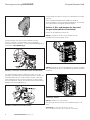
Schritt 1: Entfernen Sie die vier Schrauben von der
Fontabdeckung (zwei an jeder Seite).
Abbildung 5. Schritt 1
Schritt 2: Entfernen Sie die Frontabdeckung, ziehen Sie dabei
den Handhebel herunter, um die Abdeckung leichter entfernen
zu können.
Abbildung 6. Schritt 2
Schritt 3: Machen Sie sich mit den
Steuerleitungsanschlussleiste des Festeinbauschalters ver-
traut.
nmerkung:A Die Anschlusspositionen an den
Steuerleitungsanschlüssen sind entsprechend markiert.

3
EATON CORPORATION www.eaton.com
Gültig ab Dezember 2010
Montageanweisung IL01301037E
Abbildung 7. Schritt 3
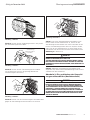
Schritt 4: Stecken Sie den Verbindungsstecker in den jeweili-
gen Steuerleitungsanschlussblock.
Steuerleitungs
anschlussblock
Festeinbau
Abbildung 8. Schritt 4
Schritt 5: Stecken Sie den Steuerleitungsanschlussblock
mit der Unterseite zuerst in die jeweilige Position der
Steuerleitungsanschlussleiste.
Halteklammern
Abbildung 9. Schritt 5
Schritt 6: Drücken Sie den Steuerleitungsanschlussblock oben
gegen die Steuerleitungsanschlussleiste bis er einrastet.
4
3
5
7
9
11
13
15
17
19
21
23
25
27
OT1M
OT2B
OT2M
ALM1
ALM2
ALMC
OT2C
OT1B
OT1C
N2
G2
G1
N1
SGF1
AGND
CMM2
CMM1
+24V
SGF2
CMM4
CMM3
ZOOM
ZOUT
UV2
UV1
6
8
10
12
14
16
18
20
22
24
26
28
30
32
34
9
11
13
15
17
19
21
23
25
27
OT2B
OT2M
ALM1
ALM2
ALMC
OT2C
OT1B
N2
G2
G1
N1
SGF1
AGND
CMM2
CMM1
+24V
SGF2
CMM3
8
10
12
14
16
18
20
22
4
3
1
5
7
9
1
1
13
15
17
19
21
23
25
27
OT1M
OT2B
OT2M
ALM1
ALM2
ALMC
OT2C
OT1B
OT1C
N2
G2
G1
N1
SGF1
AGND
CMM2
CMM1
+24V
SGF2
CMM4
CMM3
ZOOM
ZOU
T
UV2
UV1
6
8
10
12
14
16
18
20
22
24
26
28
30
32
34
14
13
Abbildung 10. Schritt 6
Schritt 7: Um einen Steuerleitungsanschlussblock zu ent-
fernen, heben Sie die Halteklammer an, ziehen Sie den
Steuerleitungsanschlussblock nach vorne und heben Sie ihn
heraus. Der Verbindungsstecker kann nun entfernt werden,
indem Sie die zwei Halteklemmen mit einer Zange zusam-
mendrücken und den Anschlussstecker herausziehen (siehe
Abbildung 4 in Abschnitt 1)
WICHTIG
EINEN VERBINDUNGSSTECKER IN EINEM FESTEINBAUSCHALTER
WIEDER ZU ENTFERNEN, MUSS ZUERST DER
STEUERLEITUNGSANSCHLUSSBLOCK ENTFERNT WERDEN. SOBALD
DER STEUERLEITUNGSANSCHLUSSBLOCK ENTFERNT IST, KANN DER
VERBINDUNGSSTECKER ENTFERNT WERDEN (SIEHE ABBILDUNG 4 IN
ABSCHNITT 1).
Schritt 8: Sobald alle Steuerleitungsanschlussblöcke sicher
eingesetzt sind, setzten Sie die Frontabdeckung wieder auf und
schrauben Sie diese wieder fest.
Abschnitt 3: Ein- und Ausbau der Steuerlei-
tungsanschlussblöcke (Ausfahrtechnik)
WICHTIG
BEACHTEN SIE, DASS STEUERLEITUNGSANSCHLÜSSE AN DEN
HALTELEISTEN DER KASSETTE BEFESTIGT WERDEN (ABBILDUNG
11). ANSCHLUSSSTECKER VON ZUBEHÖRLEITUNGEN WERDEN AN
STECKVERBINDUNGEN AM LEISTUNGSSCHALTER ANGESCHLOSSEN
(ABBILDUNG 12). BEIM AUSFAHREN DES SCHALTERS AUS DER
KASSETTE WERDEN STEUERLEITUNGSANSCHLÜSSE AUTOMATISCH
GETRENNT.ANSCHLUSSSTECKER MÜSSEN DAHER NICHT ENTFERNT
WERDEN BEVOR STEUERLEITUNGSANSCHLUSSBLÖCKE EIN- ODER
AUSGEBAUT WERDEN.

4
EATON CORPORATION www.eaton.com
Montageanweisung IL01301037E
Gültig ab Dezember 2010
Abbildung 11. Steuerleitungsanschlussblock, Ausfahrtechnik
1600A
Abbildung 11a. Steuerleitungsanschlussblock, Ausfahrtechnik
4000A
Abbildung 12. Steckverbindungen am Leistungsschalter
Führen Sie die folgenden Schritte aus:
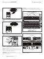
Schritt 1: Machen Sie sich mit den Verbindungssteckern des
Schalters und der Steuerleitungsanschlussleiste der Kassette
vertraut (siehe Abbildung 1, Abschnitt 1).
nmerkung:A Die Anschlusspositionen an den
Steuerleitungsanschlüssen sind entsprechend markiert. (siehe
Abbildung 13, 13a und 14).
1
2
nmerkung:A Die Steuerleitungsanschlussblöcke werden von
eine Halteklammer in Position gehalten. Diese muss vor dem
Ein- oder Ausbau von Steuerleitungsnaschlussblöcken entfernt
werden.
Abbildung 13. Schritt 1a
Abbildung 13a. Schritt 1a
Halteklammer der Anschlusspositionen
Markierung der Anschlusspositionen

Abbildung 14. Schritt 1a
Schritt 2: Entfernen Sie die vier Befestigungsschrauben der
Halteklammer.
Abbildung 15. Schritt 2
Schritt 3: Entfernen Sie vorsichtig die Halteklemme.
Abbildung 16. Schritt 3
Schritt 4: Setzen Sie den Steuerleitungsanschlussblock auf
die untere Anschlussleiste.
Abbildung 17. Schritt 4
Schritt 5: Lassen Sie den Steuerleitungsanschlussblock in die
obere Anschlussleiste einschnappen. Stellen Sie sicher, dass
der Steuerleitungsanschlussblock fest an der Anschlussleiste
sitzt und korrekt positioniert ist.
Abbildung 18. Schritt 5
5
EATON CORPORATION www.eaton.com
Gültig ab Dezember 2010
Montageanweisung IL01301037E

Schritt 6: Wiederholen Sie die Schritte 4 und 5, bis alle
Steuerleitungsanschlussblöcke korrekt montiert sind.
Abbildung 19. Schritt 6
Schritt 7: Schieben Sie die Halteklemme wieder vorsichtig in
ihre ursprüngliche Position ein.
Abbildung 20. Schritt 7
Schritt 8: Überprüfen Sie, ob die Trennstifte der Haltklammer
korrekt zwischen den Steuerleitungsanschlussblöcken sitzen.
Abbildung 21. Schritt 8
Schritt 9: Setzen sie die Befestigungsschrauben der
Halteklemme wieder ein und ziehen Sie sie fest.
Abbildung 22. Schritt 9
Step 10: Um Steuerleitungsanschlussblöcke zu entnehmen,
entfenren Sie zuerst die Haltklemme.
Schritt 11: Um einen Steuerleitungsanschlussblock zu ent-
fernen, setzen Sie einen Schraubendreher in die Ausparung
des Klemm-Clips und heben Sie den Clip an, um den
Steuerleitungsanschlussblock herausschnappen zu lassen.
Abbildung 23. Schritt 11
Schritt 12: Nachdem alle gewünschten
Steuerleitungsanschlussblöcke entfernt wurden, befestigen
Sie wieder die Haltklemme. Achten Sie darauf, dass alle
Trennstifte zwischen den Steuerleitungsanschlussblöcken sit-
zen.
6
EATON CORPORATION www.eaton.com
Montageanweisung IL01301037E
Gültig ab Dezember 2010

Montageanweisung IL01301037E
Gültig ab Dezember 2010
Eaton Corporation
Electrical Group
1000 Cherrington Parkway
Moon Township, PA 15108
United States
877-ETN-CARE (877-386-2273)
Eaton.com
© 2010 Eaton Corporation
All Rights Reserved
Printed in USA
Publication No. IL01301037E
Dezember 2010
PowerChain Management is a registered
trademark of Eaton Corporation.
All other trademarks are property of their
respective owners.
-
 1
1
-
 2
2
-
 3
3
-
 4
4
-
 5
5
-
 6
6
-
 7
7
-
 8
8
-
 9
9
-
 10
10
-
 11
11
-
 12
12
-
 13
13
-
 14
14
-
 15
15


Eaton IL01301037E: Series NRX Bedienungsanleitung
- Typ
- Bedienungsanleitung
- Dieses Handbuch eignet sich auch für
in anderen Sprachen
Verwandte Artikel
-
Eaton NRX RF Instruction Leaflet
-
-
-
Eaton IL01301013E Benutzerhandbuch
-
-
-
-
-
-