
Installation Instructions for Series NRX
Ethernet Communications Adapter
Module
effective May 2012 Series NRXInstruction Leaet IL01301052E
• WARNING
(1) ONLY QUALIFIED ELECTRICAL PERSONNEL SHOULD BE PERMITTED TO WORK
ON THE EQUIPMENT.
(2) ALWAYS DE-ENERGIZE PRIMARY AND SECONDARY CIRCUITS IF A CIRCUIT
BREAKER CANNOT BE REMOVED TO A SAFE WORK LOCATION.
(3) DRAWOUT CIRCUIT BREAKERS SHOULD BE LEVERED (RACKED) OUT TO THE
DISCONNECT POSITION.
(4) ALL CIRCUIT BREAKERS SHOULD BE SWITCHED TO THE OFF POSITION AND
MECHANISM SPRINGS DISCHARGED.
FAILURE TO FOLLOW THESE STEPS FOR ALL PROCEDURES DESCRIBED IN THIS
INSTRUCTION LEAFLET COULD RESULT IN DEATH, BODILY INJURY, OR PROPERTY
DAMAGE.
• WARNING
THE INSTRUCTIONS CONTAINED IN THIS IL AND ON PRODUCT LABELS HAVE TO
BE FOLLOWED. OBSERVE THE FIVE SAFETY RULES:
– DISCONNECTING
– ENSURE THAT DEVICES CANNOT BE ACCIDENTALLY RESTARTED
– VERIFY ISOLATION FROM THE SUPPLY
– EARTHING AND SHORT-CIRCUITING
– COVERING OR PROVIDING BARRIERS TO ADJACENT LIVE PARTS
DISCONNECT THE EQUIPMENT FROM THE SUPPLY. USE ONLY AUTHORIZED
SPARE PARTS IN THE REPAIR OF THE EQUIPMENT. THE SPECIFIED MAINTENANCE
INTERVALS AS WELL AS THE INSTRUCTIONS FOR REPAIR AND EXCHANGE MUST
BE STRICTLY ADHERED TO PREVENT INJURY TO PERSONNEL AND DAMAGE TO
THE SWITCHBOARD.
Instructions apply to:
1600 NRX SUB-TITLE IMAGE (12/15/2010)
Series NRX, Type NF Frame
ANSI, UL1066, UL489 / IEC, IZMX16, IZM91
Series NRX, Type RF Frame
IEC, IZMX40
4000 NRX RF DRAWOUT SUBTITLE IMAGE (12/15/2010)

2
EATON CORPORATION www.eaton.com
Installation Instructions for Series NRX
Ethernet Communications Adapter
Module
Instruction Leaet IL01301052E
effective May 2012
Section 1: General information
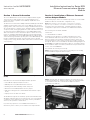
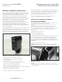
The Series NRX Ethernet Communications Adapter Module (Figure
1) is an accessory that operates as a communicating device in
conjunction with a compatible Series NRX trip unit/breaker via an
Ethernet network.
The Ethernet Communications Adapter Module (ECAM) provides Web-
enabled monitoring and control of the Series NRX trip unit metering,
logging, alarms, and control functions using a standard web browser. It
also includes alarms; command, event, and data logging; configuration
of setpoint, alarm, and logging parameters; and control functions such
as open/close breaker. Additionally, the Series NRX ECAM provides
data communications to the Eaton Power Xpert Software as an easy
means of centralizing and gathering data for long-term data archival,
analysis, and trending. The Series NRX 520M trip unit supports basic
current monitoring and status reporting. The Series NRX 1150 trip unit
provides expanded functionality associated with current, demand,
voltage, power, energy, breaker health, temperature measurement and
event reporting.
Figure 1. Series NRX Ethernet Communications Adapter Module
(ECAM)
Each Ethernet Communications Adapter Module provides:
•
Circuit Breaker Open/Close/Reset Control
•
NRX Trip Unit Source/Residual Ground Selection
•
Flashing Status LED indicating module has power
•
Ethernet Control Enable/Disable selection jumper
•
DIN rail mounting (11mm H, 28mmW DIN rail minimum require-
ment)
•
Input power for module from 24 Vdc
The ECAM is designed to be installed, operated, and maintained by
adequately trained people. These instructions do not cover all details
or variations of the equipment for its storage, delivery, installation,
checkout, safe operation or maintenance.
If you have any questions or need additional information or
instructions, please contact your local Eaton Sales representative.
Section 2: Installation of Ethernet Communi-
cations Adapter Module
The following steps outline the installation procedure for a Series NRX
ECAM in a drawout circuit breaker configuration only.
ote:N Many illustrations use the NF Frame circuit breaker for illustrative
purposes only. The RF Frame circuit breaker is handled in a similar fashion.
For fixed mounted circuit breakers, a separate DIN rail mounting
configuration is preferred. Consult Eaton for additional information.
The following tools should be available:
•
#T-15 Torx
•
Small flat blade screwdriver
For drawout circuit breakers, secondary terminal blocks as well
as the ECAM are DIN rail mounted on the top front portion of the
drawout cassette. The module is designed to install or replace the
four terminal blocks (eight contacts in total) at secondary contacts 19
through 26. Refer to the Series NRX Circuit Breaker Wiring Diagrams in
TD01301014E. For additional information relative to secondary terminal
block installation and/or removal beyond that which is presented in this
section, refer to IL01301037E.
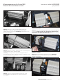
Proceed with the following seven steps:
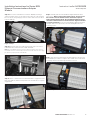
Step 1: Using a T-15 Torx, remove the four mounting screws holding
the Terminal Block Alignment Bracket in place.
Figure 2. Step 1
Step 2: Carefully slide the alignment bracket out from between any
mounted terminal blocks, and put it aside with its mounting hardware
for re-installment after the communications adapter module is
connected to the DIN rail.
Figure 3. Step 2

3
EATON CORPORATION www.eaton.com
Instruction Leaet IL01301052E
effective May 2012
Installation Instructions for Series NRX
Ethernet Communications Adapter
Module
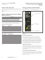
Step 3: Remove the terminal block in location 19/20 by inserting a
small screwdriver in the recessed area in the top front of the terminal
block as shown, and gently pry down to release and remove the block
from the DIN rail.
Figure 4. Step 3
Step 4: Repeat the same procedure performed in Step 3 to remove
terminal blocks at locations 21/22, 23/24 and 25/26.
ote:N The extra DIN rail mounting screw located in the space where the four
terminal blocks were mounted may need to be removed to allow the unit’s pogo
pin ground to properly hit the metal DIN rail.
Figure 5.
Mounting Screw
Step 4
Step 5: Tilt the communications module backward to engage the lower
part of the DIN rail, and then snap it back into the DIN rail for complete
engagement.
Figure 6. Step 5
Step 6: Carefully slide the Terminal Block Alignment Bracket back
into position. Before securing the bracket in place, inspect it from
the bottom to ensure that the teeth on the bracket separate
each individual terminal block. One installed terminal block only
should be visible between two teeth when the alignment bracket
is properly positioned. Secure the Terminal Block Alignment bracket
using the four screws previously removed. Hand tighten the four
mounting screws.
Figure 7. Step 6
Step 7: A mounted communications module appears as shown, and
the installation procedure is complete. The module can now be wired
in keeping with the information presented in Section 3
Figure 8. Step 7

4
EATON CORPORATION www.eaton.com
Installation Instructions for Series NRX
Ethernet Communications Adapter
Module
Instruction Leaet IL01301052E
effective May 2012
Section 3: Basic wiring rules
The ECAM communication wiring requires a shielded Ethernet cable.
Please refer to the IMPACC™ wiring specification TD17513 for detailed
wiring instructions.
ote:N For technical documents please go to www.eaton.com and search for
“TD17513”.
Section 4: Ethernet Communications Adapter
Module Connections
• WARNING
ALL APPLICABLE SAFETY CODES, SAFETY STANDARDS, AND SAFETY
REGULATIONS MUST BE STRICTLY ADHERED TO WHEN INSTALLING,
OPERATING, OR MAINTAINING THIS EQUIPMENT. FAILURE TO COMPLY
COULD RESULT IN DEATH, BODILY INJURY, OR PROPERTY DAMAGE.
For installation specifics, refer to Figures 10 and 11 on pages 5 and
6 respectively for wiring diagrams, as well as pin out Table 1 (power
connections) and Table 2 (Ethernet connections) on this page.
Table 1. Power Connector Pin-Outs j
Pin Number Input Signal
1 24 Vdc +
2 24 Vdc -
3 Control signal common
4 Control open signal
5 Control close signal
j Module power uses a 5-pin input connector. Power requirement is 24 Vdc, 10 watts.
Table 2. Ethernet Connector Pin-Outs j
RJ45 Pin Number 10/100 Base-T Signal
1 Transmit +
2 Transmit -
3 Receive +
4
Unused
5
Unused
6
Receive -
7
Unused
8
Unused
j The Ethernet connection uses an 8-pin grounded RJ-45 connector. A shielded Ethernet cable is
recommended.
Section 5: Jumpers and indicator LEDS
Refer to Figure 9 to become familiar with specific jumper and LED
locations on the Ethernet Communications Adapter Module.
Figure 9.
Status LED j
Control
Jumper
k
Source Ground
Jumper
l
ECAM Communications Adapter Module (Front View
Closeup)
MicroController LED (Status) j
The Status indicator will be flashing green when the module is
powered up and the microprocessor is executing instructions.
On power-up the Status LED will be red for approximately 45
seconds while the module boots. When the Series NRX Ethernet
Communications Adapter Module is connected to a Series NRX trip
unit for the first time, this LED will alternately flash red and green to
signal a learning process between both units. This automatic process
will take approximately 20 seconds and occurs only once during
the initial startup. The LED will also flash red if the module is not
connected or unable to communicate with a Series NRX trip unit.
Ethernet Control Jumper k
The Ethernet Control jumper provides the user with a means of
enabling or disabling remote communication control commands to the
Series NRX trip unit. With the jumper placed in the “Enable” position,
remote control commands, such as open, close and reset can be
executed. With the jumper in the “Disable” position, commands will
not be accepted.
Source/residual ground selection jumper l
The Source Ground jumper selects the protection configuration for
Series NRX trip units with ground fault protection or ground fault alarm
functionality. Consult the Series NRX trip unit instructions for further
information on ground sensing. This jumper is not applicable for non-
ground fault style trip units.

5
EATON CORPORATION www.eaton.com
Instruction Leaet IL01301052E
effective May 2012
Installation Instructions for Series NRX
Ethernet Communications Adapter
Module
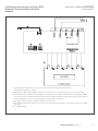
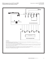
Figure 10.
j
The Series NRX Communication Module is a separate device that snaps into the Din Rail starting at locations 19 through 26.
(Removal of the four contact blocks is required.)
k
The Communications Module voltage requirement is 24VDC ±10% and should be sourced from a high quality supply (6 watts is the burden of the CAM).
l
A shielded CAT5, CAT5e, or CAT6 cable for 10/100 Mb/s Ethernet is recommended. The shielded cable is recommended for the best communication reliability
in industrial environments. The metal jack provides a ground to the housing on the Ethernet Communications Adapter Module, which is grounded to the breaker
housing via the CAM ground pin. Be sure to ground the breaker housing per the instructions in the breaker IL.
m
Set the jumper on the module to enable or disable the communications control as desired.
n
When the Communications Module is employed and Source Ground or Zero Sequence Ground Sensing method is required, the Ground Fault function is enabled
by this jumper.
o
Use shielded Ethernet cable.
Series NRX Ethernet Communication with Digitrip 520M

6
EATON CORPORATION www.eaton.com
Installation Instructions for Series NRX
Ethernet Communications Adapter
Module
Instruction Leaet IL01301052E
effective May 2012
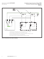
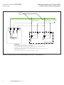
Figure 11.
Communications
Module
5
1
2
4
1
3
4
4
Shunt Trip Spring Release
Series NRX Circuit Breaker
j
Spring Release and Shunt Trip wiring as shown for optional communication close or open capability.
k
Choose Spring Release coil voltage rating as desired if communication is required.
l
Choose Shunt Trip voltage rating to be the same as Spring Release voltage rating if communication is required.
m
Control Power voltage rating must match ST and SR coil voltage rating.
n
Close duration is two seconds on communication activation when comm control is enabled.
Communications Control (SR and ST Wiring)

7
EATON CORPORATION www.eaton.com
Instruction Leaet IL01301052E
effective May 2012
Installation Instructions for Series NRX
Ethernet Communications Adapter
Module
Section 6: Viewing/setting Ethernet address
The Series NRX trip unit is used as the means to display and modify
the programmed Ethernet settings of the ECAM Module. All modules
are shipped with the following factory default settings:
DHCP Enabled False
IP Address 10.0.0.2
Subnet Mask /26
Default Gateway 10.0.0.1 (the first two bytes are the same as the IP
Address)
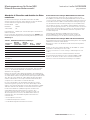
For the Series NRX Ethernet Communications Adapter Module, nine
communication settings are available and can be viewed as shown in
Table 3. A block diagram of the setting sequence and programming
options is shown in Figure 12.
Table 3. ECAM Communication Setting Ranges
Setpoint
NRX 520M
Setting
Number Name
NRX 1150
Setting
Number Default
Allowable
Range
DHCP Enabled SP00 DHCP 0 0 = False; 1 =
True
IP Address MSB SP01 IP1 10 0 to 255
IP Address SP02 IP2 0 0 to 255
IP Address SP03 IP3 0 0 to 255
IP Address LSB SP04 IP4 2 0 to 255
Subnet Mask (CIDR Notation) SP05 CIDR 26 16 to 32
Default Gateway SP06 GW IP3 0 0 to 255
Default Gateway SP07 GW IP4 1 0 to 255
Reset Pin
SP08 RST PIN 0 0 to 255
The Subnet Mask uses Classless Inter-Domain Routing (CIDR)
notation to minimize the number of setpoints required. In CIDR
notation, a prefix is shown as a 4-octet quantity, followed by the
“/” (slash) character, followed by a decimal value between 0 and 32
that describes the number of significant bits. For example, network
192.168.0.0 with a network mask of 255.255.0.0 is represented as
192.168.0.0/16, with the “/16” indicating the most significant 16
bits are ones and the least significant 16 bits are zeros. Similarly,
192.168.99.0/26 indicates the most significant 26 bits are ones
and the least significant 6 bits are zero. This represents a mask of
255.255.255.192, resulting in 64 available addresses from 192.168.99.0
to 192.168.99.63 for devices on this subnet.
The first 2 bytes of the default Gateway are the same as the first 2
bytes of the IP Address. The last 2 bytes (octets) are set as SP06 and
SP07.
The Reset PIN setpoint (SP08) is provided to clear passwords and
ECAM configuration information. Three special numeric values may be
entered to clear the Control Password, reset the admin password, or
reset the ECAM configuration information:
•
9 Reset control password
•
15 Reset admin password
•
31 Reset ECAM configuration information
NRX 520M Trip Unit Communication Settings
To set or view the settings using the Series NRX 520M Trip Unit,
depress and hold the Reset/Battery Test Button located on the front
of the trip unit for approximately five seconds until the address
information is displayed. This button must be held in continuously
during the process. The Series NRX trip unit display will then alternate
between ‘SP00’ and the programmed DHCP setting.
To change the DHCP selection, depress the trip unit SCROLL Display
Button to increment the value shown. Users may simultaneously
depress and hold in the SCROLL and Reset/Battery Test Buttons for
fast advance. The next setting will be displayed when the Reset/Battery
Test Button is released and then once again depressed.
Once the last setting (SP08) has been viewed and the Reset/Battery
Test Button has been released, the new network setttings will be
saved to the Series NRX 520M Trip Unit.
NRX 1150 Trip Unit Communication Settings
Programming the communication settings using the NRX 1150
graphical user interface follows a similar procedure.
Press the <ESC> button to navigate to the top level display.
Use the right and left arrow buttons to navigate to the PGM Set icon.
Press the <SEL> button to select the PGM Set menu.
Scroll down to “Comm Settings” and press the <SEL> button.
Scroll through the Comm Settings (SP00 to SP08) using the right and
left arrow buttons. Change the values using the up and down arrow
buttons. Press the <SAVE> button to save the communication settings.

8
EATON CORPORATION www.eaton.com
Installation Instructions for Series NRX
Ethernet Communications Adapter
Module
Instruction Leaet IL01301052E
effective May 2012
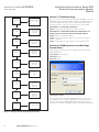
SP00
SP01
SP02
SP03
SP04
SP05
SP06
SP07
DHCP Enhabled
0 = no 1 = yes
IP Address MSB
(1st octet)
0 to 255
IP Address
(2nd octet)
0 to 255
IP Address
(3rd octet)
0 to 255
IP Address LSB
(4th octet)
0 to 255
Subnet
Mask
Default Gateway
IP Address
(3rd octet)
0 to 255
Default Gateway
IP Address
(4th octet)
0 to 255
SP08
Reset PIN
Figure 12. Setting Sequence Programming Flow Chart
Section 7: Troubleshooting
The most common issues experienced with the installation of a Series
NRX Ethernet Communications Adapter Module are addressed below.
If you have additional questions or need further information and/or
instructions, please contact your local Eaton sales representative.
Observation 1—Status LED not flashing
Action—Verify proper input power to module connectors.
Observation 2—Status LED flashing, but module does not
change state in response to master command requests
Action—Verify correct module address.
Action—Verify communication cable is connected correctly from
master to module
Action—Verify Ethernet Control jumper is in the Enable position
Section 8: ECAM Operation and Web Page
Screen Shots
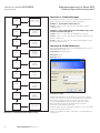
The following screen shots show the ECAM web interface with an
NRX 520M trip unit.
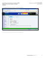
Login Screen: Default login is:
User name: admin
Password: admin
Screen Shot 1. Login
The first action after powering the ECAM module is to set the clock.
This software clock is not battery backed up, so time will be lost if
power is cycled with an NRX 520M Trip Unit. Proper time setting is
required for accurate time stamping of data, command, and event logs.

9
EATON CORPORATION www.eaton.com
Instruction Leaet IL01301052E
effective May 2012
Installation Instructions for Series NRX
Ethernet Communications Adapter
Module
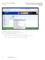
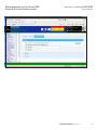
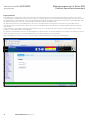
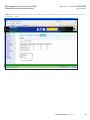
Select “ECAM Configuration” then “Date/Time” to configure the ECAM clock.
Screen Shot 2.
Click the Locale tab and select the proper time zone from the drop-down list.

10
EATON CORPORATION www.eaton.com
Installation Instructions for Series NRX
Ethernet Communications Adapter
Module
Instruction Leaet IL01301052E
effective May 2012
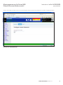
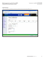
Screen Shot 3.
Click <Apply Settings> for the selected Time Zone to take effect.
Browse to the Synchronization tab under ECAM Configuration then Date/Time.
Three options are provided for time synchronization:
1. NTP – select NTP, enter up to 3 NTP server IP addresses, and click <Use NTP>
2. Manual – select Manual and click <Use Manual> to execute a manual time update using the PC clock
3. Trip Unit – select and click <Use Trip Unit> to permit the Trip Unit to set ECAM time.

11
EATON CORPORATION www.eaton.com
Instruction Leaet IL01301052E
effective May 2012
Installation Instructions for Series NRX
Ethernet Communications Adapter
Module
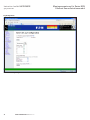
Screen Shot 4.
Verify the proper time.

12
EATON CORPORATION www.eaton.com
Installation Instructions for Series NRX
Ethernet Communications Adapter
Module
Instruction Leaet IL01301052E
effective May 2012
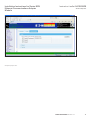
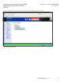
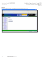
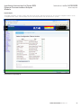
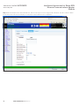
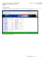
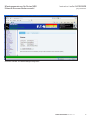
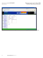
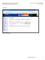
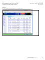
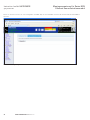
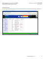
Screen Shot 5. Data View -> Summary: Default web page to View Trip Unit info, status, and currents

13
EATON CORPORATION www.eaton.com
Instruction Leaet IL01301052E
effective May 2012
Installation Instructions for Series NRX
Ethernet Communications Adapter
Module
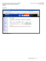
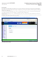
Click the Controls hyperlink: Open/Close breaker if enabled, Enable/Disable Maintenance Mode, Reset Trip
Screen Shot 6. Trip Unit Control

14
EATON CORPORATION www.eaton.com
Installation Instructions for Series NRX
Ethernet Communications Adapter
Module
Instruction Leaet IL01301052E
effective May 2012
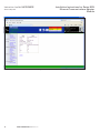
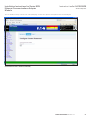
Data View
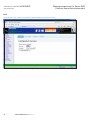
Setpoints NRX 520M Trip Unit provides only View Setpoints
Screen Shot 7. Data View - Setpoints

15
EATON CORPORATION www.eaton.com
Instruction Leaet IL01301052E
effective May 2012
Installation Instructions for Series NRX
Ethernet Communications Adapter
Module
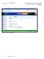
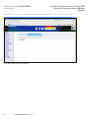
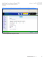
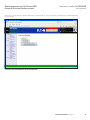
Alarm Status
View active alarms; Acknowledge/Close active alarms; Save alarms to a file.
Screen Shot 8. Alarm Status

16
EATON CORPORATION www.eaton.com
Installation Instructions for Series NRX
Ethernet Communications Adapter
Module
Instruction Leaet IL01301052E
effective May 2012
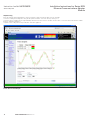
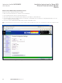
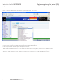
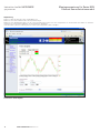
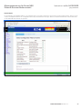
Graphical Log
Enter the starting and ending dates by clicking on Date box and selecting the date from the calendar.
Select the starting and ending time using the drop down indicator. Select the time by clicking on it.
Select the value to graph from the right hand drop down box for Plot Selection. Double click the value or select the value and click the <Add>
button to graph the parameter.
Separate y axis scaling values are provided for each value graphed.
Screen Shot 9. Trend Graphs

17
EATON CORPORATION www.eaton.com
Instruction Leaet IL01301052E
effective May 2012
Installation Instructions for Series NRX
Ethernet Communications Adapter
Module
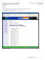
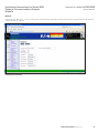
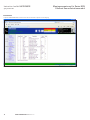
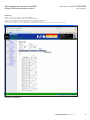
Data Log
Enter the starting and ending dates by clicking on Date box and selecting the date from the calendar.
Select the starting and ending time using the drop down indicator. Select the time by clicking on it.
Enter the number of rows to display on the page in the table Height box.
Click <Apply> to view the logged data.
The Data Log can be saved to a file or erased using the buttons provided.
Screen Shot 10. Data Logs

18
EATON CORPORATION www.eaton.com
Installation Instructions for Series NRX
Ethernet Communications Adapter
Module
Instruction Leaet IL01301052E
effective May 2012
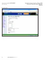
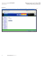
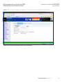
Event Log
Either View or Erase the Event Log using the buttons provided. <View the log> opens a csv file.
Screen Shot 11. Event

19
EATON CORPORATION www.eaton.com
Instruction Leaet IL01301052E
effective May 2012
Installation Instructions for Series NRX
Ethernet Communications Adapter
Module
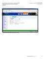
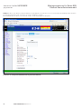
Command Log
Displays active, terminated, and denied commands executed.
Screen Shot 12. Commands

20
EATON CORPORATION www.eaton.com
Installation Instructions for Series NRX
Ethernet Communications Adapter
Module
Instruction Leaet IL01301052E
effective May 2012
Access Control
The customer can configure ECAM to allow different levels of security for different users. When the customer first logs into ECAM using the
admin, admin login credentials, they are referred to as the “Superuser”. The “Superuser” has the ability to edit/delete user names, update the
ECAM firmware, and reset the ECAM to factory settings. For added security the “Superuser” password can only be changed via the setpoints
interface from the NRX trip unit.
The next level of user is the Administrative User or “aUser” (username begins with an a). The “aUser” can view and control the Trip Unit, but
cannot update the firmware, reset to factory defaults, or create/delete usernames and passwords.
The lowest level of security is the “User” ” (username begins with a u). The “User” can only view the data on ECAM. All other functions are
disabled at this level.
An optional control password can be configured to provide additional security for control functions. This password only needs to be entered once
and remains in effect until the web browser session is closed.
The first tab (Web Server) on the Access Control/web page allows the user to change the Ethernet port.
Screen Shot 13. Access Control
Seite wird geladen ...
Seite wird geladen ...
Seite wird geladen ...
Seite wird geladen ...
Seite wird geladen ...
Seite wird geladen ...
Seite wird geladen ...
Seite wird geladen ...
Seite wird geladen ...
Seite wird geladen ...
Seite wird geladen ...
Seite wird geladen ...
Seite wird geladen ...
Seite wird geladen ...
Seite wird geladen ...
Seite wird geladen ...
Seite wird geladen ...
Seite wird geladen ...
Seite wird geladen ...
Seite wird geladen ...
Seite wird geladen ...
Seite wird geladen ...
Seite wird geladen ...
Seite wird geladen ...
Seite wird geladen ...
Seite wird geladen ...
Seite wird geladen ...
Seite wird geladen ...
Seite wird geladen ...
Seite wird geladen ...
Seite wird geladen ...
Seite wird geladen ...
Seite wird geladen ...
Seite wird geladen ...
Seite wird geladen ...
Seite wird geladen ...
Seite wird geladen ...
Seite wird geladen ...
Seite wird geladen ...
Seite wird geladen ...
Seite wird geladen ...
Seite wird geladen ...
Seite wird geladen ...
Seite wird geladen ...
Seite wird geladen ...
Seite wird geladen ...
Seite wird geladen ...
Seite wird geladen ...
-
 1
1
-
 2
2
-
 3
3
-
 4
4
-
 5
5
-
 6
6
-
 7
7
-
 8
8
-
 9
9
-
 10
10
-
 11
11
-
 12
12
-
 13
13
-
 14
14
-
 15
15
-
 16
16
-
 17
17
-
 18
18
-
 19
19
-
 20
20
-
 21
21
-
 22
22
-
 23
23
-
 24
24
-
 25
25
-
 26
26
-
 27
27
-
 28
28
-
 29
29
-
 30
30
-
 31
31
-
 32
32
-
 33
33
-
 34
34
-
 35
35
-
 36
36
-
 37
37
-
 38
38
-
 39
39
-
 40
40
-
 41
41
-
 42
42
-
 43
43
-
 44
44
-
 45
45
-
 46
46
-
 47
47
-
 48
48
-
 49
49
-
 50
50
-
 51
51
-
 52
52
-
 53
53
-
 54
54
-
 55
55
-
 56
56
-
 57
57
-
 58
58
-
 59
59
-
 60
60
-
 61
61
-
 62
62
-
 63
63
-
 64
64
-
 65
65
-
 66
66
-
 67
67
-
 68
68


Eaton IL01301052E: NRX Bedienungsanleitung
- Typ
- Bedienungsanleitung
- Dieses Handbuch eignet sich auch für
in anderen Sprachen
Verwandte Artikel
-
Eaton NRX Series Instruction Leaflet
-
Eaton Series NRX Instruction Leaflet
-
-
-
-
-
-
-
-

