
Operating instructions
Betriebsanleitung
EN
DE
Digitalanzeige, Typ DI32-1
Digital indicator, model DI32-1
Digital indicator, model DI32-1

EN
14122699.03 03/2020 EN/DE
DE
WIKA operating instructions digital indicator, model DI32-12
Operating instructions model DI32-1 Page 3 - 68
© 2015 WIKA Alexander Wiegand SE & Co. KG
All rights reserved. / Alle Rechte vorbehalten.
WIKA
®
is a registered trademark in various countries.
WIKA
®
ist eine geschützte Marke in verschiedenen Ländern.
Prior to starting any work, read the operating instructions!
Keep for later use!
Vor Beginn aller Arbeiten Betriebsanleitung lesen!
Zum späteren Gebrauch aufbewahren!
Further languages can be found on www.wika.com
Betriebsanleitung Typ DI32-1 Seite 69 - 134

EN
WIKA operating instructions digital indicator, model DI32-1 3
14122699.03 03/2020 EN/DE
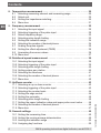
1. General information ..........................................6
2. Design and function ..........................................7
2.1 Overview ..................................................7
2.2 Description ................................................8
2.3 Scope of delivery ...........................................8
3. Safety ......................................................9
3.1 Explanation of symbols. . . . . . . . . . . . . . . . . . . . . . . . . . . . . . . . . . . . . . . 9
3.2 Intended use ...............................................9
3.3 Improper use ..............................................10
3.4 Personnel qualification ......................................10
3.5 Labelling, safety marks ...................................... 11
4. Transport, packaging and storage .............................12
4.1 Transport .................................................12
4.2 Packaging and storage ...................................... 12
5. Commissioning .............................................13
5.1 Requirements for the installation location .......................13
5.2 Mounting .................................................13
5.3 Electrical connection .......................................14
5.4 Switching on the digital indicator ..............................14
5.5 Connection examples ....................................... 15
6. Operation ..................................................20
6.1 Key functions .............................................. 20
6.2 Menu navigation ...........................................20
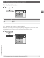
6.3 Setting the numeric values ...................................21
6.4 Accessing and exiting programming mode ...................... 21
7. Voltage or current measurement ...............................22
7.1 Selecting the input signal and measuring range .................. 22
7.2 Setting the indication range ..................................23
7.3 Selecting the number of decimal places ........................23
7.4 Scaling the input signal ......................................24
7.5 Setting the offset adjustment (TARE) ..........................24
7.6 Setting the zero point suppression ............................24
7.7 Select the overrun and underrun behaviour .....................25
7.8 Linearising the sensor values .................................26
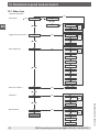
7.9 Menu tree ................................................27
Contents
Contents

EN
WIKA operating instructions digital indicator, model DI32-14
14122699.03 03/2020 EN/DE
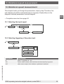
8. Temperature measurement ...................................29
8.1 Selecting measuring element and measuring range ..............29
8.2 Select unit ................................................30
8.3 Setting the impedance matching ..............................30
8.4 Menu tree ................................................31
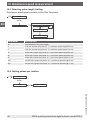
9. Frequency measurement .....................................32
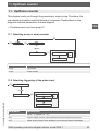
9.1 Selecting the input signal ....................................32
9.2 Selecting triggering of the pulse input ..........................32
9.3 Select frequency range. . . . . . . . . . . . . . . . . . . . . . . . . . . . . . . . . . . . . . 33
9.4 Selecting pulse length limiting ................................33
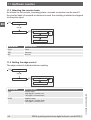
9.5 Setting the indication range ..................................34
9.6 Selecting the number of decimal places ........................34
9.7 Scaling the pulse signals ....................................35
9.8 Setting the offset adjustment (TARE) ..........................35
9.9 Linearising the sensor values .................................36
9.10 Menu tree ................................................37
10. Rotational speed measurement ...............................39
10.1 Selecting the input signal ....................................39
10.2 Selecting triggering of the pulse input ..........................39
10.3 Selecting pulse length limiting ................................40
10.4 Setting pulses per rotation ...................................40
10.5 Selecting the time base .....................................41
10.6 Selecting the number of decimal places ........................41
10.7 Menu tree ................................................42
11. Up/Down counter ............................................43
11.1 Selecting an up or down counter ..............................43
11.2 Selecting triggering of the pulse input ..........................43
11.3 Selecting the counter basis ..................................44
11.4 Setting the edge control .....................................44
11.5 Setting the prescaler ........................................ 45
11.6 Selecting pulse length limiting ................................45
11.7 Setting the upper indication value and upper pulse count value .....46
11.8 Selecting the number of decimal places ........................46
11.9 Menu tree ................................................47
12. General settings ............................................49
12.1 Setting the measuring time. . . . . . . . . . . . . . . . . . . . . . . . . . . . . . . . . . . 49
12.2 Setting the moving average determination ......................49
12.3 Limiting the indication range .................................50
12.4 Assigning key functions .....................................50
Contents

EN
WIKA operating instructions digital indicator, model DI32-1 5
14122699.03 03/2020 EN/DE
12.5 Selecting display blinking ....................................51
12.6 Menu tree ................................................52
13. Switching outputs ...........................................53
13.1 Selecting the switching function. . . . . . . . . . . . . . . . . . . . . . . . . . . . . . . 53
13.2 Setting a switching window (window function) ...................54
13.3 Selecting switch behaviour for limit value errors .................. 54
13.4 Selecting switch behaviour ...................................55
13.5 Setting the switching threshold ...............................55
13.6 Setting the hysteresis .......................................56
13.7 Setting the switch-off delay ..................................56
13.8 Setting the switch-on delay ..................................56
13.9 Menu tree ................................................57
14. Password protection .........................................60
14.1 Setting the password .......................................60
14.2 Activating/deactivating the password protection .................60
14.3 Menu tree ................................................61
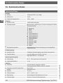
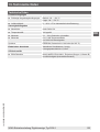
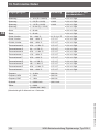
15. Factory settings ............................................. 62
15.1 Restoring factory settings ....................................62
15.2 Overview of the factory settings ............................... 62
16. Faults .....................................................63
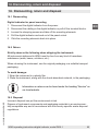
17. Maintenance and cleaning ....................................64
17.1 Maintenance ..............................................64
17.2 Cleaning .................................................64
18. Dismounting, return and disposal. . . . . . . . . . . . . . . . . . . . . . . . . . . . . . 65
18.1 Dismounting ..............................................65
18.2 Return ...................................................65
18.3 Disposal .................................................. 65
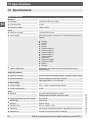
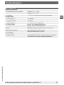
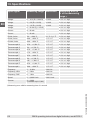
19. Specifications ..............................................66
Declarations of conformity can be found online at www.wika.com
Contents

EN
WIKA operating instructions digital indicator, model DI32-16
14122699.03 03/2020 EN/DE
1. General information
1. General information
■
The digital indicator described in these operating instructions has been
designed and manufactured using state-of-the-art technology. All components
are subject to stringent quality and environmental criteria during production. Our
management systems are certied to ISO 9001 and ISO 14001.
■
These operating instructions contain important information on handling the
instrument. Working safely requires that all safety instructions and work instruc-
tions are observed.
■
Observe the relevant local accident prevention regulations and general safety
regulations for the instrument's range of use.
■
The operating instructions are part of the product and must be kept in the
immediate vicinity of the instrument and readily accessible to skilled personnel
at any time. Pass the operating instructions onto the next operator or owner of
the instrument.
■
Skilled personnel must have carefully read and understood the operating
instructions prior to beginning any work.
■
The general terms and conditions contained in the sales documentation shall
apply.
■
Subject to technical modications.
■
Further information:
- Internet address: www.wika.de / www.wika.com
- Relevant data sheet: AC 80.13
- Application consultant: Tel.: +49 9372 132-0
Fax: +49 9372 132-406

EN
WIKA operating instructions digital indicator, model DI32-1 7
14122699.03 03/2020 EN/DE
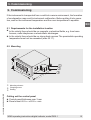
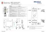
2. Design and function
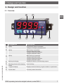
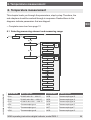
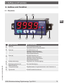
2.1 Overview
2. Design and function
Designation Description
[☼] key Programming mode is accessed
Changes to a deeper parameter level
[▼] key MIN memory is accessed
Changes lower limit values
Changes between parameters
Changes parameter values
[▲] key MAX memory is accessed
Changes lower limit values
Changes between parameters
Changes parameter values
Switch point display Displays the status of the switching outputs
Mounting element with clamping
screws
Used for xing
7-segment display Displays measured values, program numbers or parameters
Product label Contains product information

EN
WIKA operating instructions digital indicator, model DI32-18
14122699.03 03/2020 EN/DE
2.2 Description
The DI32-1 is a 4-digit digital indicator for the measurement of dierent measure-
ment signals (voltage, current, temperature and frequency). The conguration is
made via three front keys. Password protection prevents unwanted changes to the
parameters.
With the two semiconductor switching outputs, limits can be monitored and
signalled to a control room. The electrical connections are made at the rear via
plug-in terminals.
Functions
■
Retrieval of the MIN/MAX values
■
Tare function
■
Averaging function
■
Adjustable switching thresholds
■
Linearisation of the measuring input
2.3 Scope of delivery
■
Digital indicator
■
Sealing
■
2 mounting elements
■
Operating instructions
Cross-check scope of delivery with delivery note.
2. Design and function

EN
WIKA operating instructions digital indicator, model DI32-1 9
14122699.03 03/2020 EN/DE
3. Safety
3. Safety
3.1 Explanation of symbols
WARNING!
... indicates a potentially dangerous situation that can result in
serious injury or death, if not avoided.
CAUTION!
... indicates a potentially dangerous situation that can result in light
injuries or damage to equipment or the environment, if not avoided.
Information
... points out useful tips, recommendations and information for
ecient and trouble-free operation.
3.2 Intended use
The DI32-1 digital indicator is designed for the evaluation and display of sensor
signals. With the switching outputs, it is possible to realise simple control functions.
The digital indicator is not permitted to be used in hazardous areas.
Only use the digital indicator in applications that lie within its technical perfor-
mance limits (e.g. max. ambient temperature).
→ Performance limits see chapter 19 “Specications”.
The instrument has been designed and built solely for the intended use described
here, and may only be used accordingly.
The manufacturer shall not be liable for claims of any type based on operation
contrary to the intended use.

EN
WIKA operating instructions digital indicator, model DI32-110
14122699.03 03/2020 EN/DE
3. Safety
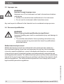
3.3 Improper use
WARNING!
Injuries through improper use
Improper use of the instrument can lead to hazardous situations
and injuries.
▶
Refrain from unauthorised modications to the instrument.
▶
Do not use the instrument within hazardous areas.
Any use beyond or dierent to the intended use is considered as improper use.
3.4 Personnel qualification
WARNING!
Risk of injury should qualication be insucient
Improper handling can result in considerable injury and damage to
equipment.
▶
The activities described in these operating instructions may
only be carried out by personnel who have the qualications
described below.
Skilled electrical personnel
Skilled electrical personnel are understood to be personnel who, based on
their technical training, know-how and experience as well as their knowledge
of country-specic regulations, current standards and directives, are capable
of carrying out work on electrical systems and independently recognising and
avoiding potential hazards. The skilled electrical personnel have been specically
trained for the work environment they are working in and know the relevant stand-
ards and regulations. The skilled electrical personnel must comply with current
legal accident prevention regulations.

EN
WIKA operating instructions digital indicator, model DI32-1 11
14122699.03 03/2020 EN/DE
3. Safety
3.5 Labelling, safety marks
Product label
The product label is located on the upper side of the digital indicator.
Serial number
Model
Pin assignment
Symbols
Before mounting and commissioning the instrument, ensure you
read the operating instructions!
1V, 2V, mA, Freq., Pt100(0)
987654321
Out 1: NPN, PNP
Out 2: NPN, PNP
GND
DI32-1
50mV, TC, Pt100, Reset
GND, Pt100(0)
10V, PNP
L- / GND
L+ / DC 9...28V
Power
supply
Input Outputs
Serial No.
WIKA Alexander Wiegand SE & Co. KG
63911 Klingenberg
•
Germany
•
www.wika.com
Digitalanzeige / Digital Indicator DI32-1
Hilfsenergie / Power Supply
Bestell-Nr. / Order No.
Eingang / Input
Schaltpunkte / Switching Outputs
14110042
:
:
:
: Multi-function
DC 9...28 V
2

EN
WIKA operating instructions digital indicator, model DI32-112
14122699.03 03/2020 EN/DE
4. Transport, packaging and storage
4. Transport, packaging and storage
4.1 Transport
Check the digital indicator for any damage that may have been caused by transport.
Obvious damage must be reported immediately.
CAUTION!
Damage through improper transport
With improper transport, damage to property can occur.
▶
When unloading packed goods upon delivery as well as during
internal transport, proceed carefully and observe the symbols on
the packaging.
▶
With internal transport, observe the instructions in chapter 4.2
“Packaging and storage”.
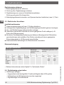
4.2 Packaging and storage
Do not remove packaging until just before mounting.
Keep the packaging as it will provide optimum protection during transport (e.g.
change in installation site, sending for repair).
Permissible conditions at the place of storage:
■
Storage temperature: -30 ... +70 °C
■
Humidity: 0 ... 85 % relative humidity (no condensation)
Avoid exposure to the following factors:
■
Direct sunlight or proximity to hot objects
■
Mechanical vibration, mechanical shock (putting it down hard)
■
Soot, vapour, dust and corrosive gases
Store the digital indicator in its original packaging in a location that fulls the condi-
tions listed above. If the original packaging is not available, pack and store the
instrument as described below:
1. Wrap the instrument in a plastic lm.
2. Place the instrument, along with the shock-absorbent material, in the packaging.

EN
WIKA operating instructions digital indicator, model DI32-1 13
14122699.03 03/2020 EN/DE
5. Commissioning
If the instrument is transported from a cold into a warm environment, the formation
of condensation may result in instrument malfunction. Before putting it into opera-
tion, wait for the instrument temperature and the room temperature to equalise.
5.1 Requirements for the installation location
■
In the vicinity there should be no magnetic or electrical elds, e.g. from trans-
formers, radio-telephones or electrostatic discharges.
■
In the vicinity there should be no strong heat sources. The permissible operating
temperature must not be exceeded (max. 50 °C).
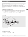
5.2 Mounting
Mounting element
Clamping screw
Sealing
Cutting out the control panel
■
Control panel thickness max. 3 mm
■
Panel cutout 45.0
+0.6
x 22.2
+0.3
mm
24,0
4
8
,
0
Di
c
ht
u
n
g
3
,
0
E
i
n
b
a
u
t
i
e
f
e e
i
n
s
c
hl
i
eß
l
i
c
h
A
ns
c
h
l
us
sk
l
e
mm
e
6
7
m
m
5
2
,
0 mm
5. Commissioning

EN
WIKA operating instructions digital indicator, model DI32-114
14122699.03 03/2020 EN/DE
Installing the digital indicator
1. Remove the mounting elements.
2. Slide the seal over the digital indicator.
3. Slide the digital indicator into the control panel from the front.
Check the seal is properly seated.
4. Lock the mounting elements into place and tighten the clamping screws (max.
0.1 Nm).
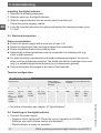
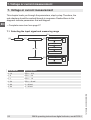
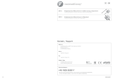
5.3 Electrical connection
Notes on installation
■
Protect the power supply with a slow fuse of max. 2 A.
■
Route the signal input lines and signal output lines separately.
■
Route outward and return lines side-by-side.
■
Galvanically isolated potentials must be connected to a suitable point (e.g.
earth or plant ground).
■
For high-accuracy requirements and small measurement signals, the sensor
wires must be shielded and twisted. The shield should be connected at one end
only to a suitable equipotential bonding (e.g. measurement ground).
■
Avoid electrostatic discharges in the area of the terminals.
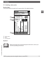
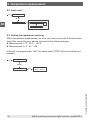
Terminal conguration
9-pin terminal block
Signal inputs Power supply
(not galvanically
isolated)
Switch points (not galvanically
isolated)
9 8 7 6 5 4 3 2 1
DC 1 V
DC 2 V
mA
Frequency
Pt100
Pt1000
50 mV
TC
Pt100
Reset
GND
Pt100
Pt1000
DC 10 V
Freq.PNP
U- U+ GND OUT2
NPN
PNP
OUT1
NPN
PNP
→ For further information see chapter 19 “Specications”.
5.4 Switching on the digital indicator
▶
Connect the power supply.
» Segment test is carried out. Check the correct operation of all LEDs
» Software type and software version are displayed.
» Digital indicator is ready for operation.
5. Commissioning

EN
WIKA operating instructions digital indicator, model DI32-1 15
14122699.03 03/2020 EN/DE
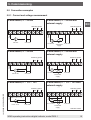
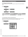
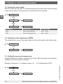
5. Commissioning
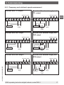
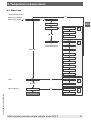
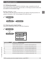
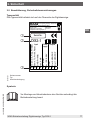
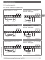
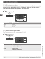
5.5 Connection examples
5.5.1 Current and voltage measurement
2-wire sensor, 4 ... 20 mA
3-wire sensor, 4 ... 20 mA with
external supply
2-wire sensor, 4 ... 20 mA with
external supply
3-wire sensor, 4 ... 20 mA
3-wire sensor, 0 ... 1/2 ... 10 V 3-wire sensor, 0 ... 1/2 ... 10 V with
external supply
Switching points
4-20 mA
_
+
9-28 VDC
0/4-20 mA
_
+
Transmitter
supply
9
876
54
321
Signal
GND S2 S1
Switching points
0/4-20 mA
_
+
9-28 VDC
9
876
54
321
Signal
GND S2 S1
_
+
Switching points
0-1/2...10 V
_
+
9-28 VDC
9
876
54
321
Signal
GND S2 S1
_
+
10 V
1/2 V
Switching points
0-1/2...10 V, 50 mV
_
+
9-28 VDC
9
876
54
321
Signal
GND S2 S1
_
+
10 V
1/2 V
50 mV
Switching points
9
876
54
321
GND S2 S1
_
+
9-28 VDC
Signal
Switching points
9
876
54
321
GND S2 S1
_
+
9-28 VDC
0-1/2...10 V
_
Transmitter
supply
Switching points
9
876
54
321
GND S2 S1
_
+
9-28 VDC
Signal
1/2 V 10 V
0-1/2...10 V,
50 mV
Transmitter
supply
Switching points
9
876
54
321
GND S2 S1
_
+
9-28 VDC
Signal
1/2 V
10 V
50 mV
0/4-20 mA
_
+
Transmitter
supply
Signal
_
+
_
_
+
+
9-28 VDC
1 VA
<
_
10V, PNP (HTL)
GND, Pt100 (0)
50mV, TC, Pt100, Reset
1V, 2V, mA, Frequency, Pt100(0)
9
876
54
321
_
Signal input
Voltage
supply
Semi-conductor
outputs
Switchpoint 1
Switchpoint 2
GND
Switching points
4-20 mA
_
+
9-28 VDC
0/4-20 mA
_
+
Transmitter
supply
9
876
54
321
Signal
GND S2 S1
Switching points
0/4-20 mA
_
+
9-28 VDC
9
876
54
321
Signal
GND S2 S1
_
+
Switching points
0-1/2...10 V
_
+
9-28 VDC
9
876
54
321
Signal
GND S2 S1
_
+
10 V
1/2 V
Switching points
0-1/2...10 V, 50 mV
_
+
9-28 VDC
9
876
54
321
Signal
GND S2 S1
_
+
10 V
1/2 V
50 mV
Switching points
9
876
54
321
GND S2 S1
_
+
9-28 VDC
Signal
Switching points
9
876
54
321
GND S2 S1
_
+
9-28 VDC
0-1/2...10 V
_
Transmitter
supply
Switching points
9
876
54
321
GND S2 S1
_
+
9-28 VDC
Signal
1/2 V 10 V
0-1/2...10 V,
50 mV
Transmitter
supply
Switching points
9
876
54
321
GND S2 S1
_
+
9-28 VDC
Signal
1/2 V
10 V
50 mV
0/4-20 mA
_
+
Transmitter
supply
Signal
_
+
_
_
+
+
9-28 VDC
1 VA
<
_
10V, PNP (HTL)
GND, Pt100 (0)
50mV, TC, Pt100, Reset
1V, 2V, mA, Frequency, Pt100(0)
9
876
54
321
_
Signal input
Voltage
supply
Semi-conductor
outputs
Switchpoint 1
Switchpoint 2
GND

EN
WIKA operating instructions digital indicator, model DI32-116
14122699.03 03/2020 EN/DE
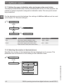
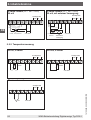
5.5.2 Temperature measurement
Pt100, 3-wire
Pt1000, 2-wire
Thermocouple
4-wire sensor, 0 ... 1/2 ... 10 V, 50 mV
4-wire sensor, 0 ... 1/2 ... 10 V,
50 mV, with external supply
5. Commissioning
Switching points
9
876
54
321
GND S2
S1
_
+
9-28 VDC
Pt100
Switching points
9
876
54
321
GND S2 S1
_
+
9-28 VDC
Pt1000
Switching points
9
876
54
321
GND S2 S1
_
+
9-28 VDC
TC
+
_
Switching points
9
876
54
321
GND S2 S1
_
+
9-28 VDC
IN
TTL
Encoder Supply
_
+
Switching points
9
876
54
321
GND S2 S1
_
+
9-28 VDC
IN
TTL
Encoder Supply
_
+
_
+
Sensor
supply
NPN
Switching points
9
876
54
321
GND S2 S1
_
+
9-28 VDC
IN
Encoder
Supply
_
+
Switching points
9
876
54
321
GND S2 S1
_
+
9-28 VDC
IN
Supply
_
+
_
+
Sensor
supply
NPN
Encoder
Switching points
9
876
54
321
GND S2 S1
_
+
9-28 VDC
IN
PNP
Encoder Supply
_
+
Switching points
9
876
54
321
GND S2 S1
_
+
9-28 VDC
IN
PNP
Encoder Supply
_
+
_
+
Sensor
supply
Switching points
9
876
54
321
GND S2 S1
_
+
9-28 VDC
Pt100
Switching points
9
876
54
321
GND S2 S1
_
+
9-28 VDC
Pt1000
Switching points
9
876
54
321
GND S2 S1
_
+
9-28 VDC
TC
+
_
Switching points
9
876
54
321
GND S2 S1
_
+
9-28 VDC
IN
TTL
Encoder Supply
_
+
Switching points
9
876
54
321
GND S2 S1
_
+
9-28 VDC
IN
TTL
Encoder Supply
_
+
_
+
Sensor
supply
NPN
Switching points
9
876
54
321
GND S2 S1
_
+
9-28 VDC
IN
Encoder
Supply
_
+
Switching points
9
876
54
321
GND S2 S1
_
+
9-28 VDC
IN
Supply
_
+
_
+
Sensor
supply
NPN
Encoder
Switching points
9
876
54
321
GND S2 S1
_
+
9-28 VDC
IN
PNP
Encoder Supply
_
+
Switching points
9
876
54
321
GND S2 S1
_
+
9-28 VDC
IN
PNP
Encoder Supply
_
+
_
+
Sensor
supply
Switching points
4-20 mA
_
+
9-28 VDC
0/4-20 mA
_
+
Transmitter
supply
9
876
54
321
Signal
GND S2 S1
Switching points
0/4-20 mA
_
+
9-28 VDC
9
876
54
321
Signal
GND S2 S1
_
+
Switching points
0-1/2...10 V
_
+
9-28 VDC
9
876
54
321
Signal
GND S2 S1
_
+
10 V
1/2 V
Switching points
0-1/2...10 V, 50 mV
_
+
9-28 VDC
9
876
54
321
Signal
GND S2 S1
_
+
10 V
1/2 V
50 mV
Switching points
9
876
54
321
GND S2 S1
_
+
9-28 VDC
Signal
Switching points
9
876
54
321
GND S2 S1
_
+
9-28 VDC
0-1/2...10 V
_
Transmitter
supply
Switching points
9
876
54
321
GND S2 S1
_
+
9-28 VDC
Signal
1/2 V 10 V
0-1/2...10 V,
50 mV
Transmitter
supply
Switching points
9
876
54
321
GND S2 S1
_
+
9-28 VDC
Signal
1/2 V
10 V
50 mV
0/4-20 mA
_
+
Transmitter
supply
Signal
_
+
_
_
+
+
9-28 VDC
1 VA
<
_
10V, PNP (HTL)
GND, Pt100 (0)
50mV, TC, Pt100, Reset
1V, 2V, mA, Frequency, Pt100(0)
9
876
54
321
_
Signal input
Voltage
supply
Semi-conductor
outputs
Switchpoint 1
Switchpoint 2
GND
Switching points
4-20 mA
_
+
9-28 VDC
0/4-20 mA
_
+
Transmitter
supply
9
876
54
321
Signal
GND S2 S1
Switching points
0/4-20 mA
_
+
9-28 VDC
9
876
54
321
Signal
GND S2 S1
_
+
Switching points
0-1/2...10 V
_
+
9-28 VDC
9
876
54
321
Signal
GND S2 S1
_
+
10 V
1/2 V
Switching points
0-1/2...10 V, 50 mV
_
+
9-28 VDC
9
876
54
321
Signal
GND S2 S1
_
+
10 V
1/2 V
50 mV
Switching points
9
876
54
321
GND S2 S1
_
+
9-28 VDC
Signal
Switching points
9
876
54
321
GND S2 S1
_
+
9-28 VDC
0-1/2...10 V
_
Transmitter
supply
Switching points
9
876
54
321
GND S2 S1
_
+
9-28 VDC
Signal
1/2 V 10 V
0-1/2...10 V,
50 mV
Transmitter
supply
Switching points
9
876
54
321
GND S2
S1
_
+
9-28 VDC
Signal
1/2 V
10 V
50 mV
0/4-20 mA
_
+
Transmitter
supply
Signal
_
+
_
_
+
+
9-28 VDC
1 VA
<
_
10V, PNP (HTL)
GND, Pt100 (0)
50mV, TC, Pt100, Reset
1V, 2V, mA, Frequency, Pt100(0)
9
876
54
321
_
Signal input
Voltage
supply
Semi-conductor
outputs
Switchpoint 1
Switchpoint 2
GND

EN
WIKA operating instructions digital indicator, model DI32-1 17
14122699.03 03/2020 EN/DE
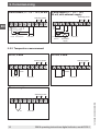
5. Commissioning
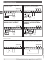
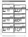
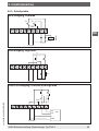
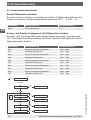
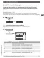
5.5.3 Frequency and rotational speed measurement
Encoder with TTL output
Encoder with external supply and
TTL output
Encoder with PNP output
Encoder with external supply and
PNP output
Encoder with NPN output Encoder with external supply and
NPN output
Switching points
9
876
54
321
GND S2 S1
_
+
9-28 VDC
Pt100
Switching points
9
876
54
321
GND S2 S1
_
+
9-28 VDC
Pt1000
Switching points
9
876
54
321
GND S2 S1
_
+
9-28 VDC
TC
+
_
Switching points
9
876
54
321
GND S2 S1
_
+
9-28 VDC
IN
TTL
Encoder Supply
_
+
Switching points
9
876
54
321
GND S2 S1
_
+
9-28 VDC
IN
TTL
Encoder Supply
_
+
_
+
Sensor
supply
NPN
Switching points
9
876
54
321
GND S2 S1
_
+
9-28 VDC
IN
Encoder
Supply
_
+
Switching points
9
876
54
321
GND S2 S1
_
+
9-28 VDC
IN
Supply
_
+
_
+
Sensor
supply
NPN
Encoder
Switching points
9
876
54
321
GND S2 S1
_
+
9-28 VDC
IN
PNP
Encoder Supply
_
+
Switching points
9
876
54
321
GND S2 S1
_
+
9-28 VDC
IN
PNP
Encoder Supply
_
+
_
+
Sensor
supply
Switching points
9
876
54
321
GND S2 S1
_
+
9-28 VDC
Pt100
Switching points
9
876
54
321
GND S2 S1
_
+
9-28 VDC
Pt1000
Switching points
9
876
54
321
GND S2 S1
_
+
9-28 VDC
TC
+
_
Switching points
9
876
54
321
GND S2 S1
_
+
9-28 VDC
IN
TTL
Encoder Supply
_
+
Switching points
9
876
54
321
GND S2 S1
_
+
9-28 VDC
IN
TTL
Encoder Supply
_
+
_
+
Sensor
supply
NPN
Switching points
9
876
54
321
GND S2 S1
_
+
9-28 VDC
IN
Encoder
Supply
_
+
Switching points
9
876
54
321
GND S2 S1
_
+
9-28 VDC
IN
Supply
_
+
_
+
Sensor
supply
NPN
Encoder
Switching points
9
876
54
321
GND S2 S1
_
+
9-28 VDC
IN
PNP
Encoder Supply
_
+
Switching points
9
876
54
321
GND S2
S1
_
+
9-28 VDC
IN
PNP
Encoder Supply
_
+
_
+
Sensor
supply
Switching points
9
876
54
321
GND S2 S1
_
+
9-28 VDC
Pt100
Switching points
9
876
54
321
GND S2 S1
_
+
9-28 VDC
Pt1000
Switching points
9
876
54
321
GND S2 S1
_
+
9-28 VDC
TC
+
_
Switching points
9
876
54
321
GND S2 S1
_
+
9-28 VDC
IN
TTL
Encoder Supply
_
+
Switching points
9
876
54
321
GND S2 S1
_
+
9-28 VDC
IN
TTL
Encoder Supply
_
+
_
+
Sensor
supply
NPN
Switching points
9
876
54
321
GND S2 S1
_
+
9-28 VDC
IN
Encoder
Supply
_
+
Switching points
9
876
54
321
GND S2 S1
_
+
9-28 VDC
IN
Supply
_
+
_
+
Sensor
supply
NPN
Encoder
Switching points
9
876
54
321
GND S2 S1
_
+
9-28 VDC
IN
PNP
Encoder Supply
_
+
Switching points
9
876
54
321
GND S2 S1
_
+
9-28 VDC
IN
PNP
Encoder Supply
_
+
_
+
Sensor
supply
Switching points
9
876
54
321
GND S2 S1
_
+
9-28 VDC
Pt100
Switching points
9
876
54
321
GND S2 S1
_
+
9-28 VDC
Pt1000
Switching points
9
876
54
321
GND S2 S1
_
+
9-28 VDC
TC
+
_
Switching points
9
876
54
321
GND S2 S1
_
+
9-28 VDC
IN
TTL
Encoder Supply
_
+
Switching points
9
876
54
321
GND S2 S1
_
+
9-28 VDC
IN
TTL
Encoder Supply
_
+
_
+
Sensor
supply
NPN
Switching points
9
876
54
321
GND S2 S1
_
+
9-28 VDC
IN
Encoder
Supply
_
+
Switching points
9
876
54
321
GND S2 S1
_
+
9-28 VDC
IN
Supply
_
+
_
+
Sensor
supply
NPN
Encoder
Switching points
9
876
54
321
GND S2 S1
_
+
9-28 VDC
IN
PNP
Encoder Supply
_
+
Switching points
9
876
54
321
GND S2 S1
_
+
9-28 VDC
IN
PNP
Encoder Supply
_
+
_
+
Sensor
supply

EN
WIKA operating instructions digital indicator, model DI32-118
14122699.03 03/2020 EN/DE
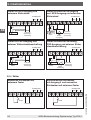
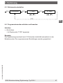
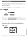
5. Commissioning
Encoder with NPN output and
external resistor
Encoder with external supply, NPN
output and external resistor
Encoder with PNP output and
external resistor connection
Encoder with external supply,
PNP output and external resistor
connection
5.5.4 Counter
Manual reset with external button
Automatic reset with output 2 and
manual reset with external button
NPN
Switching points
9
876
54
321
GND S2 S1
_
+
9-28 VDC
IN
Encoder
Voltage
supply
_
+
Switching points
9
876
54
321
GND S2 S1
_
+
9-28 VDC
IN
Voltage
supply
_
+
_
+
Sensor
supply
NPN
Encoder
RV
RV
PNP
Switching points
9
876
54
321
GND S2 S1
_
+
9-28 VDC
IN
Encoder
Voltage
supply
_
+
Switching points
9
876
54
321
GND S2 S1
_
+
9-28 VDC
Voltage
supply
+
Sensor
supply
RV1
RV1
RV2
PNP
Encoder
_
+
RV2
_
Switching points
9
876
54
321
GND S2 S1
_
+
9-28 VDC
Reset
Switching points
9
876
54
321
GND S2 S1
Reset
IN
NPN
Switching points
9
876
54
321
GND S2 S1
_
+
9-28 VDC
IN
Encoder
Voltage
supply
_
+
Switching points
9
876
54
321
GND S2 S1
_
+
9-28 VDC
IN
Voltage
supply
_
+
_
+
Sensor
supply
NPN
Encoder
RV
RV
PNP
Switching points
9
876
54
321
GND S2 S1
_
+
9-28 VDC
IN
Encoder
Voltage
supply
_
+
Switching points
9
876
54
321
GND S2 S1
_
+
9-28 VDC
Voltage
supply
+
Sensor
supply
RV1
RV1
RV2
PNP
Encoder
_
+
RV2
_
Switching points
9
876
54
321
GND S2 S1
_
+
9-28 VDC
Reset
Switching points
9
876
54
321
GND S2 S1
Reset
IN
NPN
Switching points
9
876
54
321
GND S2 S1
_
+
9-28 VDC
IN
Encoder
Voltage
supply
_
+
Switching points
9
876
54
321
GND S2 S1
_
+
9-28 VDC
IN
Voltage
supply
_
+
_
+
Sensor
supply
NPN
Encoder
RV RV
PNP
Switching points
9
876
54
321
GND S2 S1
_
+
9-28 VDC
IN
Encoder
Voltage
supply
_
+
Switching points
9
876
54
321
GND S2 S1
_
+
9-28 VDC
Voltage
supply
+
Sensor
supply
RV1
RV1
RV2
PNP
Encoder
_
+
RV2
_
Switching points
9
876
54
321
GND S2 S1
_
+
9-28 VDC
Reset
Switching points
9
876
54
321
GND S2 S1
Reset
IN
NPN
Switching points
9
876
54
321
GND S2 S1
_
+
9-28 VDC
IN
Encoder
Voltage
supply
_
+
Switching points
9
876
54
321
GND S2 S1
_
+
9-28 VDC
IN
Voltage
supply
_
+
_
+
Sensor
supply
NPN
Encoder
RV RV
PNP
Switching points
9
876
54
321
GND S2 S1
_
+
9-28 VDC
IN
Encoder
Voltage
supply
_
+
Switching points
9
876
54
321
GND S2 S1
_
+
9-28 VDC
Voltage
supply
+
Sensor
supply
RV1
RV1
RV2
PNP
Encoder
_
+
RV2
_
Switching points
9
876
54
321
GND S2 S1
_
+
9-28 VDC
Reset
Switching points
9
876
54
321
GND S2 S1
Reset
IN

EN
WIKA operating instructions digital indicator, model DI32-1 19
14122699.03 03/2020 EN/DE
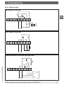
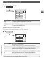
5. Commissioning
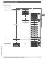
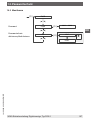
5.5.5 Switch points
NPN output, low side
PNP output, high side
Push-pull output, low side and high side
GND
S2
S1
_
+
9-28 VDC
Relay
X
9
876
54
321
_
+
9-28 VDC
X
R
L
__
L+
9
876
54
321
_
+
9-28 VDC
_
L+
IN1
IN2
L+
GND
SPS
GND
_
_
_
9
876
54
321
GND
S2
S1
_
+
9-28 VDC
Relay
X
9
876
54
321
_
+
9-28 VDC
X
R
L
__
L+
9
876
54
321
_
+
9-28 VDC
_
L+
IN1
IN2
L+
GND
SPS
GND
_
_
_
9
876
54
321
GND
S2
S1
_
+
9-28 VDC
Relay
X
9
876
54
321
_
+
9-28 VDC
X
R
L
__
L+
9
876
54
321
_
+
9-28 VDC
_
L+
IN1
IN2
L+
GND
SPS
GND
_
_
_
9
876
54
321

EN
WIKA operating instructions digital indicator, model DI32-120
14122699.03 03/2020 EN/DE
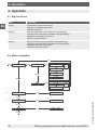
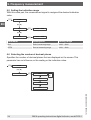
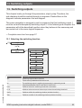
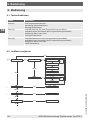
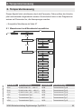
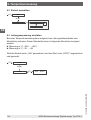
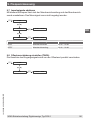
6. Operation
6.1 Key functions
Key Function
[☼] key Programming mode is accessed.
Changes to a deeper menu level.
Settings conrmed.
[▼] key Accesses MIN memory (settable via programming).
Changes lower limit values (settable via programming).
Navigates downwards in the menu.
Lowers numerical values.
[▲] key Accesses MAX memory (settable via programming).
Changes lower limit values (settable via programming).
Navigates upwards in the menu.
Increases numerical values.
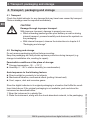
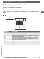
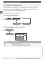
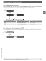
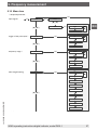
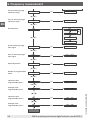
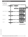
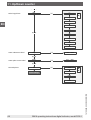
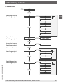
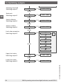
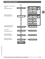
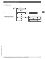
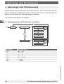
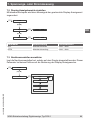
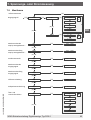
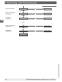
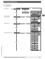
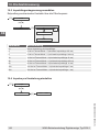
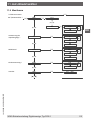
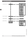
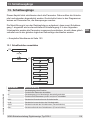
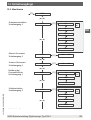
6.2 Menu navigation
TYPE VOLT
[☼]
0 … 10
[☼]
0 … 2
0 … 1
0 … 50
AMPE
[▲] [▼]
0 … 20
[☼]
4 … 20
End
[▲] [▼]
-1999 … 9999
[☼]
OFFS
[▲] [▼]
-1999 … 9999
[☼]
dot.A
[▲] [▼]
0000 … 0.000
[☼]
EndA
[▲] [▼]
-19.99 … 99.99
[☼]
OFFA
[▲] [▼]
-19.99 … 99.99
[☼]
tArA
[▲] [▼]
-1999 … 9999
[☼]
ZErO
[▲] [▼]
00 … 99
[☼]
OUEr
[▲] [▼]
no
[☼]
AdC
rAnG
5Pr
10Pr
SPC.A
[▲] [▼]
0 … 5
[☼]
dIS.1
[▲] [▼]
-1999 … 9999
[☼]
InP.1
[▲] [▼]
-1999 … 9999
[☼]
dIS.5
[▲] [▼]
-1999 … 999
[☼]
InP.5
[▲] [▼]
-1999 … 9999
[☼]
General settings
[☼]
[▲]
[▼]
[▲]
[▼]
[▲]
[▼]
[☼]
Input signal *
End of measuring range
Indication range *
Start of measuring range
Indication range *
Decimal places
End of measuring range
Input signal
Start of measuring range
Input signal
Offset adjustment
Zero point suppression
Overrun and underrun
behaviour
Number of
programmable points
Indications value
Programmable point 1
Analogue value
Programmable point 1
Indications value
Programmable point 5
Analogue va
lue
Programmable point 5
* Required parameter
6. Operation
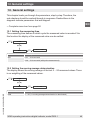
Seite wird geladen ...
Seite wird geladen ...
Seite wird geladen ...
Seite wird geladen ...
Seite wird geladen ...
Seite wird geladen ...
Seite wird geladen ...
Seite wird geladen ...
Seite wird geladen ...
Seite wird geladen ...
Seite wird geladen ...
Seite wird geladen ...
Seite wird geladen ...
Seite wird geladen ...
Seite wird geladen ...
Seite wird geladen ...
Seite wird geladen ...
Seite wird geladen ...
Seite wird geladen ...
Seite wird geladen ...
Seite wird geladen ...
Seite wird geladen ...
Seite wird geladen ...
Seite wird geladen ...
Seite wird geladen ...
Seite wird geladen ...
Seite wird geladen ...
Seite wird geladen ...
Seite wird geladen ...
Seite wird geladen ...
Seite wird geladen ...
Seite wird geladen ...
Seite wird geladen ...
Seite wird geladen ...
Seite wird geladen ...
Seite wird geladen ...
Seite wird geladen ...
Seite wird geladen ...
Seite wird geladen ...
Seite wird geladen ...
Seite wird geladen ...
Seite wird geladen ...
Seite wird geladen ...
Seite wird geladen ...
Seite wird geladen ...
Seite wird geladen ...
Seite wird geladen ...
Seite wird geladen ...
Seite wird geladen ...
Seite wird geladen ...
Seite wird geladen ...
Seite wird geladen ...
Seite wird geladen ...
Seite wird geladen ...
Seite wird geladen ...
Seite wird geladen ...
Seite wird geladen ...
Seite wird geladen ...
Seite wird geladen ...
Seite wird geladen ...
Seite wird geladen ...
Seite wird geladen ...
Seite wird geladen ...
Seite wird geladen ...
Seite wird geladen ...
Seite wird geladen ...
Seite wird geladen ...
Seite wird geladen ...
Seite wird geladen ...
Seite wird geladen ...
Seite wird geladen ...
Seite wird geladen ...
Seite wird geladen ...
Seite wird geladen ...
Seite wird geladen ...
Seite wird geladen ...
Seite wird geladen ...
Seite wird geladen ...
Seite wird geladen ...
Seite wird geladen ...
Seite wird geladen ...
Seite wird geladen ...
Seite wird geladen ...
Seite wird geladen ...
Seite wird geladen ...
Seite wird geladen ...
Seite wird geladen ...
Seite wird geladen ...
Seite wird geladen ...
Seite wird geladen ...
Seite wird geladen ...
Seite wird geladen ...
Seite wird geladen ...
Seite wird geladen ...
Seite wird geladen ...
Seite wird geladen ...
Seite wird geladen ...
Seite wird geladen ...
Seite wird geladen ...
Seite wird geladen ...
Seite wird geladen ...
Seite wird geladen ...
Seite wird geladen ...
Seite wird geladen ...
Seite wird geladen ...
Seite wird geladen ...
Seite wird geladen ...
Seite wird geladen ...
Seite wird geladen ...
Seite wird geladen ...
Seite wird geladen ...
Seite wird geladen ...
Seite wird geladen ...
Seite wird geladen ...
Seite wird geladen ...
Seite wird geladen ...
-
 1
1
-
 2
2
-
 3
3
-
 4
4
-
 5
5
-
 6
6
-
 7
7
-
 8
8
-
 9
9
-
 10
10
-
 11
11
-
 12
12
-
 13
13
-
 14
14
-
 15
15
-
 16
16
-
 17
17
-
 18
18
-
 19
19
-
 20
20
-
 21
21
-
 22
22
-
 23
23
-
 24
24
-
 25
25
-
 26
26
-
 27
27
-
 28
28
-
 29
29
-
 30
30
-
 31
31
-
 32
32
-
 33
33
-
 34
34
-
 35
35
-
 36
36
-
 37
37
-
 38
38
-
 39
39
-
 40
40
-
 41
41
-
 42
42
-
 43
43
-
 44
44
-
 45
45
-
 46
46
-
 47
47
-
 48
48
-
 49
49
-
 50
50
-
 51
51
-
 52
52
-
 53
53
-
 54
54
-
 55
55
-
 56
56
-
 57
57
-
 58
58
-
 59
59
-
 60
60
-
 61
61
-
 62
62
-
 63
63
-
 64
64
-
 65
65
-
 66
66
-
 67
67
-
 68
68
-
 69
69
-
 70
70
-
 71
71
-
 72
72
-
 73
73
-
 74
74
-
 75
75
-
 76
76
-
 77
77
-
 78
78
-
 79
79
-
 80
80
-
 81
81
-
 82
82
-
 83
83
-
 84
84
-
 85
85
-
 86
86
-
 87
87
-
 88
88
-
 89
89
-
 90
90
-
 91
91
-
 92
92
-
 93
93
-
 94
94
-
 95
95
-
 96
96
-
 97
97
-
 98
98
-
 99
99
-
 100
100
-
 101
101
-
 102
102
-
 103
103
-
 104
104
-
 105
105
-
 106
106
-
 107
107
-
 108
108
-
 109
109
-
 110
110
-
 111
111
-
 112
112
-
 113
113
-
 114
114
-
 115
115
-
 116
116
-
 117
117
-
 118
118
-
 119
119
-
 120
120
-
 121
121
-
 122
122
-
 123
123
-
 124
124
-
 125
125
-
 126
126
-
 127
127
-
 128
128
-
 129
129
-
 130
130
-
 131
131
-
 132
132
-
 133
133
-
 134
134
-
 135
135
-
 136
136


in anderen Sprachen
- English: WIKA DI32-1 Operating instructions
Verwandte Artikel
-
WIKA DI32-1 Bedienungsanleitung
-
-
-
-
-
WIKA PSD-4-ECO Bedienungsanleitung
-
-
-
-
Andere Dokumente
-
Eaton E5524E0402 Operating Instructions Manual
-
IFM DX2003 Bedienungsanleitung
-
 Minebea Intec Operation notes MP 26 Bedienungsanleitung
-
ICS IPC6 Benutzerhandbuch
-
 FuehlerSysteme LM1/E Benutzerhandbuch
-
Baumer LFFS Benutzerhandbuch
-
red lion CUB5 Benutzerhandbuch
-
-
Pepperl+Fuchs UDC-18GM50-255-3E0 Bedienungsanleitung
-
Burster 9186-Vx1xx Bedienungsanleitung

