Seite wird geladen ...

Ultraschall-Sensor
Ultrasonic Sensor
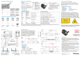
Abmessungen
Elektrischer Anschluss/Kurven/
Zusätzliche Informationen
Electrical Connection / Curves / Additional Information
Dimensions
Technische Daten
Technical data
UDC-18GM50-255-3E0
Auswerteeinheit mit
Empfangseinheit
Sendeeinheit
Litzen 70 mm mit
Aderendhülsen
l
= 0.5 m
50
30
53
M18 x 1
4
24
LEDs
ø 15
70
M18 x 1
22
24
500
l
= 2 m
-
Evaluation unit with
receiver unit
Emitter unit
wires 70 mm with
wire end ferrules
l
= 0.5 m
50
30
53
M18 x 1
4
24
LEDs
ø 15
70
M18 x 1
22
24
500
l
= 2 m
(BN)
(PK)
(WH)
(BK)
(GY)
+UB
-UB
(BU)
U
Normsymbol/Anschluss:
Doppelbogen-Kontrolle
Ausgang Doppelbogen
Ausgang Luft
Funktionseingang
Ausgang Einzelbogen
Empfohlende Abstände
Montage/Ausrichtung:
d
b
a
a
= 5 ... 15 mm
b
≥ 10 mm
d
= 40 ... 45 mm
β = 35˚
Montage/Ausrichtung:
(für sehr dicke Papiere)
a
d
b
β
α
s
α < +/- 1˚
s
< +/- 1 mm
Winkelversatz
Sensorversatz
Mounting/Adjustment
β = 35˚
(for very thick papers)
a
d
b
β
a
s
a < +/- 1°
s < +/- 1 mm
Angular misalignment
Sensor offset
Mounting/Adjustment
Recommended distances
d
b
a
a
= 5 ... 15 mm
b
≥ 10 mm
d
= 40 ... 45 mm
(BN)
(PK)
(WH)
(BK)
(GY)
+UB
-UB
(BU)
U
Standard symbol/Connection:
Double sheet control
Output double sheet
Output air
Output single sheet
Function input
Part. No.:
Date:
206522
10/02/2009 DIN A3 -> DIN
45-2965
Doc. No.:
Beschreibung der Sensorfunktionen
Der Ultraschall Doppelbogen-Sensor zur Doppelbogenerkennung wird überall dort eingesetzt, wo eine automatische Unter-
scheidung von Doppelbogen und Einzelbogen notwendig ist, um Maschinen zu schützen oder Ausschuss zu vermeiden. Der
Doppelbogen-Sensor basiert auf dem Ultraschall-Einweg-Prinzip. Es lassen sich detektieren:
- kein Bogen, d.h. Luft,
- Einzelbogen
- Doppelbogen
Die Auswertung der Signale erfolgt mit einem Mikroprozessorsystem. Als Folge derAuswertung werden die entsprechenden
Schaltausgänge gesetzt. Sich ändernde Umgebungsbedingungen wie Temperatur oder Feuchtigkeit werden automatisch
kompensiert. Die Auswerteelektronik ist in einer Auswerteeinheit zusammen mit einem Sensorkopf in einem kompakten M18
Metallgehäuse eingebaut.
Anschaltung
Der Sensor verfügt über 6 Anschlüsse. Die Funktion der Anschlüsse sind in der Nachfolgenden Tabelle aufgeführt. Der
Funktionseingang (PK) dient zur Parametrierung des Sensors. (siehe Ausgangsimpulsverlängerung, Ausrichthilfe und Pro-
grammauswahl). Im laufenden Betrieb muss der Funktionseingang immer fest mit +UB oder -UB verbunden sein, um even-
tuelle Störungen oder Fehlfunktionen zu vermeiden.
Allgemeine Daten
Erfassungsbereich 20 ... 60 mm , optimaler Abstand: 45 mm
Wandlerfrequenz 255 kHz
Anzeigen/Bedienelemente
LED grün Anzeige: Einzelbogen detektiert
LED gelb Anzeige: kein Bogen detektiert (Luft)
LED rot Anzeige: Doppelbogen detektiert
Elektrische Daten
Betriebsspannung UB18 ... 30 V DC , Welligkeit 10 %SS
Leerlaufstrom I0< 50 mA
Bereitschaftsverzug tv< 500 ms
Eingang
Eingangstyp Funktionseingang
0-Pegel: -UB ... -UB + 1V
1-Pegel: +UB - 1 V ... +UB
Impulsdauer 100 ms
Impedanz 4 k
Ausgang
Ausgangstyp 3 Schaltausgänge npn, Schließer
Bemessungsbetriebsstrom Ie3 x 100 mA , kurzschluss-/überlastfest
Spannungsfall Ud 3 V
Einschaltverzug ton ca. 15 ms (kürzere Ansprechzeit auf Anfrage)
Ausschaltverzug toff ca. 15 ms (kürzere Ansprechzeit auf Anfrage)
Normenkonformität
Normen IEC / EN 60947-5-2:2004 C-UL gelistet: 57M3, IND CONT. EQ., Betrieb an Stromversorgung Klasse 2
Umgebungsbedingungen
Umgebungstemperatur 0 ... 60 °C (273 ... 333 K)
Lagertemperatur -40 ... 85 °C (233 ... 358 K)
Mechanische Daten
Schutzart IP67
Anschluss 2 m, PVC-Kabel 0,14 mm²
Material
Gehäuse Messing, vernickelt, Kunststoffteile PBT
Wandler Epoxidharz/Glashohlkugelgemisch; Schaum Polyurethan
Masse 135 g
Farbe Anschaltung Bemerkung
BN +UB
WH Schaltausgang Einzelbogen Impulsbreite entsprechend dem Ereignis
BK Schaltausgang Doppelbogen Impulsbreite entsprechend dem Ereignis
GY Schaltausgang Luft Impulsbreite entsprechend dem Ereignis
PK -UB/+UBFunktionseingang zur Parametrierung/Impulsverlänge-
rung
BU -UB
Description of sensor functions
The ultrasonic double-sheet sensor for the detection of double sheets is used in any situation, where it is essential that a means
be provided for the automatic distinction between double and single sheets, in order to protect machinery and/or to avoid was-
te. The double-sheet sensor is based on the ultrasonic single pass principle. The following situations can be detected:
- No sheet, i.e. air
- Single sheet
- Double sheet
The evaluation of the signal is carried out with a microprocessor system. As a consequence of the evaluation the correspon-
ding switch outputs are set. Changing ambient conditions, such as temperature and humidity, are automatically compensated.
The evaluation electronics system is built into an evaluation unit, together with a sensor head, and contained in a compact M18
metal housing.
Interface
The sensor has 6 connections. The function of the connections is shown in the following table. The function input (PK) is used
to parameterize the sensor. (see Output pulse expansion, alignment aids and program select). During operation, the function
input must always be permanently connected to +UB or -UB to prevent possible faults or malfunctions.
General specifications
Sensing range 20 ... 60 mm , optimal distance: 45 mm
Transducer frequency 255 kHz
Indicators/operating means
LED green indication: single sheet detected
LED yellow Indication: No sheet detected (Air)
LED red indication: double sheet detected
Electrical specifications
Operating voltage UB18 ... 30 V DC , ripple 10 %SS
No-load supply current I0< 50 mA
Time delay before availability tv< 500 ms
Input
Input type Function input
0-level: -UB ... -UB + 1V
1-level: +UB - 1 V ... +UB
Pulse length 100 ms
Impedance 4 k
Output
Output type 3 switching outputs npn, NO
Rated operational current Ie3 x 100 mA , short-circuit/overload protected
Voltage drop Ud 3 V
Switch-on delay ton approx. 15 ms (shorter response time on request)
Switch-off delay toff approx. 15 ms (shorter response time on request)
Standard conformity
Standards IEC / EN 60947-5-2:2004 C-UL listed: 57M3, IND CONT. EQ., "Powered by Class 2 Power Source"
Ambient conditions
Ambient temperature 0 ... 60 °C (273 ... 333 K)
Storage temperature -40 ... 85 °C (233 ... 358 K)
Mechanical specifications
Protection degree IP67
Connection 2 m, PVC cable 0.14 mm²
Material
Housing brass, nickel-plated, plastic components PBT
Transducer epoxy resin/hollow glass sphere mixture; polyurethane foam
Mass 135 g
Color Interface Note
BN +UB
WH Switching output, single sheet Pulse width corresponding to the event
BK Switching output, double sheet Pulse width corresponding to the event
GY Switching output air Pulse width corresponding to the event
PK -UB/+UBFunction input (PK) for parameterization/pulse extension.
BU -UB

Adressen / Addresses / Adresses / Direcciónes / Indirizzi
Contact Pepperl+Fuchs GmbH · 68301 Mannheim · Germany · Tel. +49 621 776-4411 · Fax +49 621 776-27-4411 · E-mail: fa-info@de.pepperl-fuchs.com
Worldwide Headquarters: Pepperl+Fuchs GmbH · Mannheim · Germany · E-mail: [email protected]l-fuchs.com
USA Headquarters: Pepperl+Fuchs Inc. · Twinsburg · USA · E-mail: fa-in[email protected].com
Asia Pacific Headquarters: Pepperl+Fuchs Pte Ltd · Singapore · E-mail: [email protected]perl-fuchs.com · Company Registration No. 199003130E
For more contact-adresses refer to the catalogue or internet: http://www.pepperl-fuchs.com
Normal mode
The sensor operates in normal mode if the function input (PK) is set to -UB or +UB when the supply voltage is applied (power on)
as specified in the output pulse expansion table (see below).
Display:
Yellow LED: Air detection
Green LED: Single sheet detection
Red LED: Double sheet detection
Switching outputs:
The switching outputs are only active in normal mode!
White: WH Single sheet output
Black: BK Double sheet output
Gray: GY Air output
Output pulse expansion
A minimum pulse width of 120 ms can be selected for all the output pulses of the three switching outputs by connecting the func-
tion input (PK) to +UB.
Caution!
This can lead to a situation where more than one switching output is switched through!
Programs
The sensor has 4 programs for different application areas which allow the detection of a wide range of materials. The user can
select the program most suited to the relevant application.
The default setting program 1 is selected so that the settings of the majority of applications do not need modifying.
*) Measurements were taken under the following conditions: d = 45 mm, a = 10 mm,
= 0°
**) Measurements were taken under the following conditions: d = 45 mm, a = 10 mm,
= 35°
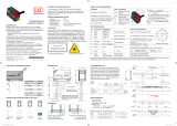
Adjustment options using the function input
The diagram below shows the adjustment options using the function input.
Program display
The preset sensor program can be displayed by disconnecting the function input (PK) from the power supply during normal ope-
ration.
The green LED indicates the program number (number of flashing pulses (1...4) = program number).
The outputs are inactive during this time.
If the function input (PK) is disconnected from the power during operation due to a fault (cable break, vibrations), the program
display also serves as a fault display. Switching to programming mode is not possible.
Programming mode
To activate programming mode,
the function input (PK) must be disconnected from the power when the supply voltage is applied (power on). The flashing green
LED connected to the sensor indicates the preset program first (number of flashing pulses (1...4) = program number).
By briefly setting the function input (PK) to -Ub (>500ms), the system is able to toggle cyclically between the amplitude control
and the program select.
When you disconnect the supply voltage, you exit programming mode and the current selected program setting is applied.
The switching outputs are deactivated while the sensor is parameterized!
Amplitude control
During installation, the amplitude control can be used to check whether the ultrasonic amplitude at the receiver is sufficient.
If the transmitter is not aligned properly in relation to the receiver, maximum sound energy is not transmitted to the receiver,
which may result in the incorrect detection of materials.
If the sensor detects the air section (yellow LED lights up), the UDC begins to display the strength of the measured amplitude
signal:
- if the signal is weak, the yellow LED flashes infrequently
- the flashing frequency increases in line with the signal strength
- the yellow LED lights up continuously when the signal strength is sufficient.
The single-sheet (green LED) and double-sheet (red LED) functions remain active so that the function of the double sheet control
can be checked.
Program select
In program select mode, briefly setting the (PK) to +Ub (>500ms) selects the next program cyclically (number of flashing pulses
from the green LED = program number). Program changes do not interrupt flashing sequences that have already started.
Note:
A complete device consists of one ultrasonic sensor and one evaluation unit with the ultrasonic receiver. The sensor heads are optimally
matched to each other in the ex-works condition and should therefore not be used separately. The connector disconnection point on the
transmitter/receiver connection cable is merely provided to simplify assembly.
Very light papers (e.g. tissues) and paper with perforations are never suitable for double sheet detection for physical reasons.
On installation, care should be taken, that the ultrasonic signal cannot pass around the material to be detected due to multiple reflections. This
can happen if, for example, there are large surfaces capable of reflecting the sound at right angles to the direction of propagation of the sound.
This can be the case when unsuitable clamping devices are used, or may be due to plant components with large surfaces. In the case of
reflecting plant components, these must either be clad with sound-absorbing material, or an alternative mounting location found for the sensor.
If a number of double sheet sensors are used in close proximity to each other, mutual interference may occur, leading to device malfunction.
Mutual interference can be avoided by suitable countermeasures implemented when planning the system.
Interface (PK) Switching behavior (after power on)
-UBNo output pulse expansion of switching outputs
+UBOutput pulse expansion of all switching outputs to a minimum of 120 ms
Program numbers Notes* Material spectrum
1 Default setting standard papers 100 - 2000 g/m2
2 Thick papers, cardboard packaging, fine corrugated cardboard
(DIN 55 468-1) and thin metal sheeting** > 300 g/m2
3 Thin papers 50 – 350 g/m2
4 Extra fine papers < 100 g/m2
+UB
-UB
-UB
-UB
+UB+UB
Power ON
Normal operation
Activate/Deactiva
output pulse
expansion
... and function input
(PK) unconnected
Function input
(PK) unconnected
... and set function input (PK)
to +UB or -UB
No function Toggle cyclically
next program
Programming
display
Programming mode
Programming
display
Amplitude control
(yellow LED)
Program select
(green LED)
Normalbetrieb
Der Sensor arbeitet im Normalbetrieb, wenn der Funktionseingang (PK) bei Anlegen der Versorgungsspannung (Power-On) auf
-UB oder +UB gelegt ist, entsprechend Tabelle Ausgangsimpulsverlängerung (siehe unten).
Anzeigen:
LED gelb: Erkennung Luft
LED grün: Erkennung Einzelbogen
LED rot: Erkennung Doppelbogen
Schaltausgänge:
Nur im Normalbetrieb sind die Schaltausgänge aktiv!
Weiß: WH Ausgang Einzelbogen
Schwarz: BK Ausgang Doppelbogen
Grau: GY Ausgang Luft
Ausgangsimpulsverlängerung
Durch Anschalten des Funktionseingangs (PK) an +UB kann eine Mindestimpulsbreite von 120 ms für alle Ausgangsimpulse der
drei Schaltausgänge gewählt werden.
Achtung:
Es kann dadurch zu einem Zustand kommen, bei dem mehr als nur ein Schaltausgang durchgeschaltet ist!
Programme
Der Sensor verfügt über 4 Programme für verschiedene Einsatzbereiche. Dies ermöglicht die Erfassung eines breiten Material-
spektrums. Der Anwender kann das für seine Applikation geeignete Programm auswählen.
Die Standardeinstellung Programm 1 ist so gewählt, dass für die Mehrheit der Applikationen keine Änderung der Einstellung
notwendig ist.
*) Die Messungen wurden bei folgenden Bedingungen aufgenommen: d = 45 mm, a = 10 mm,
= 0°
**) Die Messungen wurden bei folgenden Bedingungen aufgenommen: d = 45 mm, a = 10 mm,
= 35°
Einstellmöglichkeiten mit dem Funktionseingang
Im folgenden Diagramm sind die Einstellmöglichkeiten mit dem Funktionseingang dargestellt.
Programmanzeige
Das voreingestellte Programm des Sensors kann angezeigt werden, indem man während des Normalbetriebs den Funktionsein-
gang (PK) spannungsfrei schaltet.
Die grüne LED zeigt die Programmnummer an (Anzahl der Blinkimpulse (1...4) = Programmnummer).
Die Ausgänge sind in dieser Zeit inaktiv.
Falls während des Betriebs der Funktionseingang (PK) durch einen Fehler (Kabelbruch, Lösen durch Vibrationen) spannungsfrei
geschaltet ist, so dient die Programmanzeige als Störmeldung. Ein Wechsel in den Programmiermodus ist nicht möglich.
Programmiermodus
Um in den Programmiermodus zu gelangen, muss beim Anlegen der Versorgungsspannung (Power-On) der
Funktionseingang (PK) spannungsfrei geschaltet sein. Der Sensor zeigt zunächst das eingestellte Programm durch Blinken der
grünen LED an (Anzahl der Blinkimpulse (1...4) = Programmnummer).
Durch kurzes Tasten des Funktionseingangs (PK) auf -Ub (>500ms) kann nun zyklisch zwischen der Amplitudenkontrolle und
der Programmwahl gewechselt werden.
Durch Abtrennen der Versorgungsspannung verlassen Sie den Programmiermodus mit der gewählten Programmeinstellung.
Die Schaltausgänge sind während der Parametrierung des Sensors nicht aktiv!
Amplitudenkontrolle
Bei der Montage kann die Amplitudenkontrolle zur Überprüfung auf ausreichende Ultraschallamplitude am Empfänger verwen-
det werden.
Ist der Sender zum Empfänger nicht optimal ausgerichtet, so kommt nicht die volle Schallenergie am Empfänger an. Dies kann
dazu führen, dass Materialien nicht korrekt detektiert werden können.
Wenn der Sensor den Luftbereich erkennt (gelbe LED leuchtet), dann beginnt die UDC die Stärke des gemessenen Amplituden-
signals anzuzeigen:
- bei einem schwachen Signal blinkt die gelbe LED mit niedriger Frequenz
- mit steigender Signalstärke steigt die Blinkfrequenz
- bei ausreichender Signalstärke leuchtet die gelbe LED permanent.
Die Funktion Einzelbogen (grüne LED) und Doppelbogen (rote LED)ist hierbei weiterhin aktiv.Es kann somit die korrekte Funk-
tion der Doppelbogenkontrolle überprüft werden.
Programmwahl
Im Modus Programmwahl wird durch kurzes Tasten des Funktionseingangs (PK) auf +Ub (>500ms) zyklisch das jeweils nächste
Programm gewählt (Anzahl Blinkimpulse der grünen LED = Programmnummer). Eine begonnene Blinksequenz wird nicht durch
einen Programmwechsel unterbrochen.
Hinweise:
Ein komplettes Gerät besteht aus einem Ultraschall-Sender und einem Auswertegerät mit Ultraschall-Empfänger. Die Sensorköpfe sind ab
Werk optimal aufeinander abgestimmt und dürfen daher nicht getrennt verwendet werden. Die Stecker-Trennstelle am Verbindungskabel
Sender-Empfänger dient lediglich der leichteren Montage.
Sehr luftige Papiere (z.B. Taschentücher) oder Papiere mit Löchern sind aus physikalischen Gründen nicht immer zur Doppelbogenerkennung
geeignet.
Es ist bei der Installation darauf zu achten, dass das Ultraschallsignal das zu erfassende Material nicht durch Mehrfachreflexionen umgehen
kann. Dies kann geschehen, wenn z. B. größere Flächen zur Schallreflexion quer zur Ausbreitungsrichtung des Schalls zur Verfügung stehen.
Dies kann durch ungeeignete Haltevorrichtungen oder durch großflächige Anlagenteile der Fall sein. Im Falle reflektierender Anlagenteile,
müssen diese entweder mit Schall absorbierendem Material beklebt werden oder ein anderer Montageort gewählt werden.
Werden mehrere Doppelbogen-Sensoren in unmittelbarer Nähe eingesetzt, kann es zur gegenseitigen Beeinflussung und damit zur
Fehlfunktion der Geräte kommen. Gegenseitige Beeinflussung ist durch geeignete Gegenmaßnahmen bereits bei der Planung der Anlagen
zu vermeiden.
Anschaltung (PK) Schaltverhalten (nach Power-On)
-UBKeine Ausgangsimpulsverlängerung der Schaltausgänge
+UBAusgangsimpulsverlängerung aller Schaltausgänge auf mindestens 120 ms
Programmnummer Anmerkungen* Materialspektrum
1 Standardeinstellung Standardpapiere 100 - 2000 g/m2
2 Dicke Papiere, Kartonagen, feine Wellpappen (DIN 55 468-1) und
dünne Bleche** > 300 g/m2
3 Dünne Papiere 50 – 350 g/m2
4 Feinstpapiere < 100 g/m2
+UB
-UB
-UB
-UB
+UB+UB
Power ONNormalbetriebUmschaltung
Impulsverlängeru
... und Funktionseingang
(PK) spannungsfrei
Funktionseingang
(PK) spannungsfrei
... und Funktionseingang (PK)
auf +UB oder -UB legen
keine Funktion wähle zyklisch
nächstes Programm
Programmier-
anzeige
Programmiermodus
Programmier-
anzeige
Amplitudenkontrolle
(gelbe LED)
Programmwahl
(grüne LED)
/