
1UD18-2 | SICK
BETRIEBSANLEITUNG
OPERATING INSTRUCTIONS
UD18-2
Ultraschall-Doppellagenerkennung
Ultrasonic Double Layer Detection
de
en
8018817/10MC/2018-11-29 • Irrtümer und Änderungen vorbehalten • SICK AG • Waldkirch • Germany • www.sick.com
Deutsch
Bestimmungsgemäße Verwendung
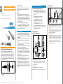
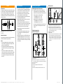
Die Ultraschall-Doppellagenerkennung UD18-2
besteht aus einem Sender und einem Empfänger mit
integrierter Auswerteeinheit. Die Ultraschall-Doppel-
lagenerkennung UD18-2 wird zur berührungslosen
Erkennung von fehlenden, einzelnen und doppelten
(mehr als einer) Materiallagen und anderen ächigen
Materialien eingesetzt.
12
Abb. 1: Ultraschall-Doppellagenerkennung UD18-2
1. Empfänger
2. Sender
Zu diesem Dokument
In diesem Dokument wird die Ultraschall-Doppel-
lagenerkennung UD18-2 vereinfacht als Sensor
bezeichnet.
Hinweise
• Die Werkseinstellungen sowie die gewählte
Empndlichkeitsstufe „Standard“ entsprechen den
Einstellungen des Vorgängermodells UM18-2001x.
• Die angegebenen Materialstärken-Werte für die
detektierbaren Materialien, wie z.B. Grammaturen,
sind typische Werte.
• Über den Connect+ Adapter (CPA) und die
Connect+ Software können Sie alle Teach-in- und
weitere Sensorparameter-Einstellungen vorneh-
men. Bestellnummer Connect+ Adapter und
Connect+ Software: 6037782.
Zu Ihrer Sicherheit
• Vor allen Arbeiten diese Betriebsanleitung auf-
merksam durchlesen. Die Betriebsanleitung in un-
mittelbarer Nähe des Sensors jederzeit zugänglich
aufbewahren.
• Nur qualizierte Fachkräfte mit einer technischen
Ausbildung dürfen an und mit dem Sensor arbei-
ten.
• Die Elektroinstallation nur durch qualizierte Elek-
trofachkraft durchführen.
• Bei Arbeiten in elektrischen Anlagen die gängigen
Sicherheitsvorschriften beachten.
• Elektrische Verbindungen zwischen dem Sensor
und anderen Geräten nur im spannungsfreien
Zustand herstellen oder trennen. Ansonsten kann
es zu Beschädigungen des Sensors und/oder der
Geräte kommen.
• Sensor nur bei trockenen und sauberen Umge-
bungsbedingungen montieren.
• Der Sensor ist kein Sicherheitsbauteil gemäß der
EG-Maschinenrichtlinie (2006/42/EG)
• Systembedingt können bei EMV-Störeinüssen
nachfolgende Störzeiten von bis zu 2 ms beim
UD18-xxCxxxx und bis zu 5 ms beim UD18-xxDxxxx
auftreten. Der Sensor ist danach wieder voll funk-
tionsfähig.
Montage und Ausrichtung
Sender und Empfänger montieren
Sender und Empfänger montieren. Dabei den
Montageabstand und die Montagehinweise be-
achten. Befestigungsmuttern maximal mit 15 Nm
anziehen.
Montageabstand Werkseinstellung:
• UD18-2xCxxxx: 40 mm ± 3 mm
• UD18-2xDxxxx: 50 mm ± 3 mm
Montageabstand möglicher Bereich:
• UD18-2xCxxxx: 20 mm … 60 mm
• UD18-2xDxxxx: 30 mm … 70 mm
Sollte der tatsächliche Montageabstand von der
Werkseinstellung abweichen, muss der Montage-
abstand eingelernt werden.
Montagehinweise
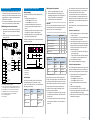
Abstände und Ausrichtung
≤ 0.5 mm
7
4
5
6
90°
± 1°
90°
± 1°
3
1
7 mm7 mm
2
2
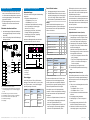
Abb. 2: Abstände und Ausrichtung
1. Arbeitsbereich
2. Blindzone: Abstand zwischen Sender oder Empfänger
und dem zu detektierenden Material von 7 mm nicht
unterschreiten
3. Montageabstand
4. Empfänger
5. Maximaler Winkel Sender und Empfänger: 2°
6. Sender
7. Maximale Koaxialität von Sender und Empfänger: 0,5 mm
Montagewinkel
1
3
4
5
6
2
∅
27° 27°… 45°
Abb. 3: Vom Material abhängige Montagewinkel
1. Senkrechte Montage: Bei Papieren und dünnen Folien
2. Montage bei dünnen Blechen oder dickeren Kunsstoff-
folien
3. Montage bei Papiersorten und Kartonagen wie z. B.
Papiere mit internen Lufteinschlüssen, die bei der senk-
rechten Montage Fehlschaltungen verursachen
4. Zu detektierendes Material
5. Materialführung
6. Aussparung: Falls der Sender versenkt eingebaut bzw.
eine Materialführung zwischen Sender und Empfänger
verwendet wird, ist für die Detektion eine Aussparung
erforderlich. Wir empfehlen für die Aussparung einen
Durchmesser von 18 mm. Sollte nur eine kleinere
Aussparung möglich sein, muss diese für die jeweilige
Applikation geprüft werden.

8018817/10MC/2018-11-29 • Irrtümer und Änderungen vorbehalten • SICK AG • Waldkirch • Germany • www.sick.com 2UD18-2 | SICK
Elektrische Installation
• Bei Anschlussleitungen mit offenem Ende darauf
achten, dass sich blanke Aderenden nicht berüh-
ren. Hier besteht Kurzschlussgefahr bei eingeschal-
teter Versorgungsspannung. Adern entsprechend
gegeneinander isolieren.
• Die Verbindungsleitungen zwischen Sender und
Empfänger nicht mit einem externen Potenzial
verbinden.
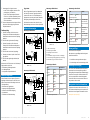
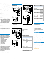
Elektrischen Anschluss durchführen
1. Anschlussleitung gemäß folgender Abbildung an
die Versorgungsspannung und an die Steuerung
anschließen.
2. Sender und Empfänger über die M8-Verbindungs-
leitungen verbinden.
1,2 m
2 m
1 m
1
2
3
M
blu
L+
brn
blk
wht
C1
vlt
C2
pnk
C3 /
Com
gra
Q1/
¯
Q1
Q2/
¯
Q2
12
3
6
4
5
Abb. 4: Elektrischer Anschluss UD18-2
1. Anschlussleitung Versorgungsspannung und Steuerung,
mit Steuereingängen C1, C2, C3 und Schaltausgängen
Q1, Q2
2. Dose M8x1, 3-polig, zum Verbinden mit Sender
3. Stecker M8x1, 3-polig, zum Verbinden mit Empfänger
4. Kommunikation über Connect+ Adapter (CPA)
5. Kein Material/Einzellage
6. Doppellage
Inbetriebnahme und Konguration
Werkseinstellungen
Die Sensoren werden mit folgender Werkseinstellung
ausgeliefert:
• Kongurierter Montageabstand von
• UD18-2xCxxxx: 40 mm ± 3 mm
• UD18-2xDxxxx: 50 mm ± 3 mm
• 3 vordenierte Empndlichkeitsstufen, abhängig
von der Beschaltung der Steuereingänge
- Siehe Tab. 2 auf Seite 2.
• Schaltausgang Q1 als Öffner „Kein Material/
Einzellage“ - Siehe folgende Abbildung.
• Schaltausgang Q2 als Öffner „Doppellage“
- Siehe folgende Abbildung.
Abweichende Montageabstände oder individuelle
Empndlichkeitsstufen können Sie einlernen.
t
1232
t
¯
Q
1
¯
Q
2
0
1
0
1
Abb. 5: Schaltzustände
1. Doppellage
2. Einzellage
3. Kein Material
Steuereingänge
Den UD18-2 gibt es als PNP- und NPN-Varianten.
Abhängig von der Variante sind für „Logisch 1 (aktiv)“
und „Logisch 0 (inaktiv)“ an den Steuereingängen
folgende Spannungen erforderlich.
Variante Logisch 1
(aktiv)
Logisch 0
(inaktiv)
PNP
(UD18-2xxxx2x)
≥ 18 V ≤ 13 V oder
Steuereingang
unbeschaltet
NPN
(UD18-2xxxx4x)
≤ 6 V ≥ 10 V oder
Steuereingang
unbeschaltet
Tab. 1: Steuereingänge – Erforderliche Spannungen
Sensor in Betrieb nehmen
1. Versorgungsspannung des Sensors einschalten.
2. Empndlichkeitsstufe wählen. Hierzu die entspre-
chenden Spannungspegel an die Steuereingänge
C1, C2 und C3 legen. - Siehe folgende Tabelle.
3. Falls erforderlich, Empndlichkeitsstufe einlernen.
Wichtig!
Sollte der tatsächliche Montageabstand von der
Werkseinstellung abweichen, zuerst den Montageab-
stand einlernen und dann die Empndlichkeitsstufe
wählen oder einlernen.
Funktion Steuereingänge
C1 C2 C3
Empndlichkeitsstufe „Standard“ 0 0 0
Empndlichkeitsstufe „Dick“ 0 1 0
Empndlichkeitsstufe „Dünn“ 1 0 0
Eingelernte Empndlichkeitsstufe 1 1 0
Teach-in ausführen 1 1 1
Tab. 2: Empndlichkeitsstufen, Teach-in ausführen
Empfohlene Emp-
ndlichkeitsstufe
Typische Richtwerte zur Detektion
von Papieren
UD18-2xCxxxx UD18-2xDxxxx
„Standard“ 50 g/m
2
bis
800 g/m
2
200 g/m
2
bis
1200 g/m
2
„Dick“ > 800 g/m
2
> 1200 g/m
2
„Dünn“ < 50 g/m
2
< 200 g/m
2
Tab. 3: Empndlichkeitsstufen
Es können auch Materialien wie z. B. Bleche, Kunst-
stoffplatten und -folien oder Wellpappe detektiert
werden. Aufgrund der unterschiedlichen Materialei-
genschaften ist eine generelle Empfehlung für die zu
wählende Empndlichkeitsstufe nicht möglich.
Wir empfehlen, zuerst die Empndlichkeitsstufe
„Standard“ zu wählen und anschließend in Abhängig-
keit des Sensorverhaltens die Empndlichkeitsstufe
anzupassen:
• Wird mit der Empndlichkeitsstufe „Standard“ bei
einer Einzellage eine Doppellage signalisiert, wäh-
len Sie die Empndlichkeitsstufe „Dick“.
• Wird mit der Empndlichkeitsstufe „Standard“ bei
einer Einzellage eine Übersteuerung signalisiert,
wählen Sie die Empndlichkeitsstufe „Dünn“.
Für Materialien, die nicht mit einer der drei vorde-
nierten Empndlichkeitsstufen detektiert werden
können, können Sie eine für das Material passende
Empndlichkeitsstufe einlernen.
In den meisten Fällen betrifft dies spezielle Materiali-
en oder Materialien, die vollständig verklebt sind wie
z.B. mit einem Wasserlm verklebte Wafer, mit einem
Öllm verklebte Bleche oder eine Klebestelle/Spleiß
auf einer Papierbahn.
Sie können die Empndlichkeitsstufen im laufenden
Betrieb umschalten.
Empndlichkeitsstufe einlernen (Teach-in)
1. Bei eingeschalteter Versorgungsspannung die
Steuereingänge C1 und C2 auf logisch 1 setzen.
2. Eine Einzellage des Materials in den Arbeitsbe-
reich zwischen Sender und Empfänger legen.
3. Steuereingang C3 für mindestens 3 Sekunden
auf logisch 1 setzen. Die LEDs blinken während-
dessen wechselseitig grün.
Materialien mit Inhomogenitäten während des
Einlernvorgangs bewegen, damit der Sensor diese
Inhomogenitäten erfassen kann.
• Ist der Teach-in erfolgreich, leuchten die LEDs
grün („Einzellage“).
• Ist der Teach-in fehlgeschlagen, blinken beide
LEDs für ca. 3 Sekunden wechselseitig rot.
Teach-in wiederholen.
4. Steuereingang C3 auf logisch 0 setzen.
Die individuelle Empndlichkeitsstufe ist einge-
lernt.
Montageabstand einlernen (Teach-in)
Falls der Montageabstand zwischen Sender und Emp-
fänger nicht dem werksseitig eingestellten Montage-
abstand entspricht, muss der neue Montageabstand
eingelernt werden.
1. Prüfen, ob der neue Montageabstand im zulässi-
gen Bereich liegt.
• UD18-2xCxxxx: 20 mm … 60 mm
• UD18-2xDxxxx: 30 mm … 70 mm
2. Alle in der Messstrecke bendlichen Materialien
entfernen.
3. Versorgungsspannung ausschalten.
4. Steuereingänge C1, C2 und C3 auf logisch 1
setzen.
5. Versorgungsspannung einschalten. Die LEDs
blinken wechselseitig schnell rot und grün.
6. Mindestens 2 Sekunden warten, bis die LEDs
wechselseitig langsam rot und grün blinken.

8018817/10MC/2018-11-29 • Irrtümer und Änderungen vorbehalten • SICK AG • Waldkirch • Germany • www.sick.com 3UD18-2 | SICK
7. Steuereingang C3 auf logisch 0 setzen.
• Ist der Teach-in erfolgreich, blinken die LEDs
gleichzeitig rot („Kein Material“).
• Ist der Teach-in fehlgeschlagen, blinken die
LEDs für ca. 3 Sekunden wechselseitig rot und
zeigen anschließend den Betriebszustand an.
Teach-in wiederholen.
Der neue Montageabstand ist eingelernt. Wählen
Sie über die Steuereingänge die gewünschte
Empndlichkeitsstufe.
Funktionsprüfung
1. Funktion „Einzellage“ prüfen. Hierzu einen
Testbogen des zu detektierenden Materials im
Arbeitsbereich zwischen Sender und Empfänger
platzieren.
Die LEDs sollten grün leuchten (Einzellage).
2. Funktion „Doppellage“ prüfen. Hierzu zwei
Testbögen des zu detektierenden Materials im
Arbeitsbereich zwischen Sender und Empfänger
platzieren.
Die LEDs sollten rot leuchten (Doppellage).
3. Funktion „Kein Material“ prüfen. Hierzu Testbö-
gen entfernen.
Die LEDs sollten gleichzeitig rot blinken (Kein
Material).
Verhalten sich die LEDs nicht wie in der Funktionsprü-
fung beschrieben, prüfen Sie:
• die Einhaltung der Montagehinweise
• den Montageabstand
• die eingestellte Empndlichkeitsstufe.
Erweiterte Konguration
Mit dem Zubehör Connect+ Adapter (CPA) und der
zugehörigen Software können Sie alle Teach-in und
weitere Sensorparameter-Einstellungen vornehmen:
• Montageabstand
• Betriebsart inkl. Trigger-Modus
• Ausgangs- und Eingangsfunktionen
• Ausschalt- und Einschaltverzögerung
• Schaltschwelle
• Zurücksetzen auf Werkseinstellung
Trigger-Modus
Mit dem Trigger-Modus können Sie die Messzyklen
des Sensors per externem Trigger-Signal individu-
ell steuern. Dies kann z. B. bei Anwendungen mit
Schuppenstrom, also einer gewünschten, teilweisen
Überlappung von Materiallagen, hilfreich sein.
Zusätzliche Informationen hierzu nden Sie in der
Betriebsanleitung der Connect+ Software (8016918).
Aufbau und Statusanzeigen
Abmessungen UD18-2xCxxx1
35,2
63,2
M18x1
1,2 m
2 m
25
3
32
21
36
M8x1
4
M8x1
M18x1
4
1 m
1
2
3
4
5
6
7
Abb. 6: Aufbau und Abmessungen UD18-2xCxxx1
(Maße in mm)
Abmessungen UD18-2xCxxx2
1,2 m
2 m
32
21
36
M8x1
M8x1
M18x1
4
1 m
1
5
6
7
34,7
79,2
25
3
M18x1 4
2
3
4
16,5
8,25
3,45
Abb. 7: Aufbau und Abmessungen UD18-2xCxxx2
(Maße in mm)
Abmessungen UD18-2xDxxx1
1,2 m
2 m
32
M8x1
1
5
36
M8x1
1 m
6
25
3
M18x1
4
2
3
4
25,5
64
10,5
∅ 22
M18x1
4
7
∅ 22
21
31,5
10,5
Abb. 8: Aufbau und Abmessungen UD18-2xDxxx1
(Maße in mm)
1. LEDs zur Statusanzeige
2. Befestigungsmutter SW 24
3. Empfänger mit Auswerteeinheit
4. Sender
5. Stecker M8x1, 3-polig, zum Verbinden mit Empfänger
6. Anschlussleitung Versorgungsspannung und Steuerung
7. Dose M8x1, 3-polig, zum Verbinden mit Sender
Statusanzeigen im Betrieb
LEDs Betriebszustand
O (Grün) O (Grün)
Einzellage
Leuchtet Leuchtet
O (Grün) O (O + O)
Orange (Grün
+ Rot)
Einzellage über-
steuert
Leuchtet Leuchtet
O (Rot) O (Rot)
Doppellage
Leuchtet Leuchtet
Ö (Rot) Ö (Rot)
Kein Material
Gleichzeitg blinkend
Tab. 4: Statusanzeigen im Betrieb
Statusanzeigen beim Teach-in
LEDs Zustand
Ö (Grün) Ö (Grün)
Teach-in ausführen
Wechselseitig blinkend
Ö (Rot) Ö (Grün)
Teach-in Montage-
abstand zwischen
Sender und Empfän-
ger
Wechselseitig blinkend
O (Grün) O (Grün)
Teach-in Emp-
ndlichkeitsstufe
erfolgreich
Leuchtet Leuchtet
Ö (Rot) Ö (Rot)
Teach-in Montage-
abstand erfolgreich
Gleichzeitig blinkend
Ö (Rot) Ö (Rot)
Teach-in fehlge-
schlagen
Wechselseitig blinkend
Tab. 5: Statusanzeigen beim Teach-in
Wartung und Pege
SICK-Sensoren sind wartungsfrei.
Wir empfehlen, in regelmäßigen Abständen folgende
Arbeiten durchzuführen:
Grenzächen vorsichtig mit Wasser reinigen.
Verschraubungen und Steckverbindungen prüfen.
Demontage und Entsorgung
Ein am Ende des Produktlebenszyklus unbrauchbar
gewordener Sensor ist umweltgerecht gemäß der
jeweils gültigen länderspezischen Abfallbeseitigungs-
vorschriften zu entsorgen. Als Elektronikschrott darf
der Sensor keinesfalls dem Hausmüll beigegeben
werden! Die SICK AG nimmt derzeit keine unbrauch-
bar gewordenen Sensor zurück.
Bezugsquellen für weitere Informationen
Ergänzende Informationen über den Sensor wie z. B.
die EG-Konformitätserklärung und sein optionales Zu-
behör nden Sie auf folgender Produktseite im Web:
www.mysick.com/de/ud18_2

8018817/10MC/2018-11-29 • Irrtümer und Änderungen vorbehalten • SICK AG • Waldkirch • Germany • www.sick.com 4UD18-2 | SICK
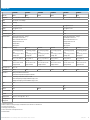
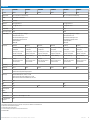
Technische Daten
Typ UD18-22CC221 UD18-22CC241 UD18-22CC222 UD18-22CC242 UD18-22DC221 UD18-22DC241
Artikelnummer 6058910 6058911 6058912 6058913 6058914 6058915
Montageabstand 20 mm … 60 mm, 40 mm ± 3 mm (Werkseinstellung) 30 mm … 70 mm, 50 mm ± 3 mm (Werkseinstellung)
Blindzone 7 mm vom Sender, 7 mm vom Empfänger
Auösung 1 Materiallage
Ansprechzeit
1), 2)
2,5 ms, Triggermodus: 0,5 ms 5,5 ms, Triggermodus: 0,5 ms
Ausgabezeit 2 ms, Triggermodus
1)
: 0,5 ms 5 ms, Triggermodus
1)
: 0,5 ms
Schaltfrequenz 250 Hz 100 Hz
Ultraschallfrequenz (typisch) 400 kHz 200 kHz
Detektierbares Material
3)
• Papiere mit Grammaturen: 20 g/m
2
… 2000 g/m
2
• Kunststoffplatten und -folien: ≤ 0,4 mm
• Bleche und selbstklebende Folien: ≤ 0,3 mm
• Wellpappe der Wellenart F, N und G
• Japanpapier (Washi)
• Wafer, Leiterplatten
• Papiere mit Grammaturen: 100 g/m
2
… 2000 g/m
2
• Kunststoffplatten und -folien: ≤ 5 mm
• Bleche und selbstklebende Folien: ≤ 2 mm
• Wellpappe der Wellenart F, N und G
• Japanpapier (Washi)
• Wafer, Leiterplatten
Schaltausgang
4)
PNP (200 mA) NPN (200 mA) PNP (200 mA) NPN (200 mA) PNP (200 mA) NPN (200 mA)
• Q1: Schaltausgang „Doppellage“,
Öffner
• Q2: Schaltausgang „Kein Material /
Einzellage“, Öffner
• Q1: Schaltausgang „Doppellage“,
Öffner
• Q2: Schaltausgang „Kein Material /
Einzellage“, Öffner
• Q1: Schaltausgang „Doppellage“,
Öffner
• Q2: Schaltausgang „Kein Material /
Einzellage“, Öffner
• Q1: Schaltausgang „Doppellage“,
Öffner
• Q2: Schaltausgang „Kein Material /
Einzellage“, Öffner
• Q1: Schaltausgang „Doppellage“,
Öffner
• Q2: Schaltausgang „Kein Material /
Einzellage“, Öffner
• Q1: Schaltausgang „Doppellage“,
Öffner
• Q2: Schaltausgang „Kein Material /
Einzellage“, Öffner
Aktiv = U
V
– (< 2 V) / Inaktiv = 0 V Aktiv ≤ 2 V / Inaktiv = U
V
Aktiv = U
V
– (< 2 V) / Inaktiv = 0 V Aktiv ≤ 2 V / Inaktiv = U
V
Aktiv ≤ 2 V / Inaktiv = U
V
Aktiv ≤ 2 V / Inaktiv = U
V
Steuereingänge • C1, C2, C3
• Aktiv ≥ 18 V, Inaktiv ≤ 13 V oder
Eingänge unbeschaltet
• C1, C2, C3
• Aktiv ≤ 6 V, Inaktiv ≥ 10 V oder
Eingänge unbeschaltet
• C1, C2, C3
• Aktiv ≥ 18 V, Inaktiv ≤ 13 V oder
Eingänge unbeschaltet
• C1, C2, C3
• Aktiv ≤ 6 V, Inaktiv ≥ 10 V oder
Eingänge unbeschaltet
• C1, C2, C3
• Aktiv ≥ 18 V, Inaktiv ≤ 13 V oder
Eingänge unbeschaltet
• C1, C2, C3
• Aktiv ≤ 6 V, Inaktiv ≥ 10 V oder
Eingänge unbeschaltet
Versorgungsspannung U
V
5)
DC 20 V … 30 V
Initialisierungszeit < 300 ms < 750 ms < 300 ms < 750 ms < 300 ms < 750 ms
Gehäusematerial • Messing vernickelt, PBT-Kunststoff, PA-Kunststoff
• Ultraschallwandler: Polyurethanschaum, Epoxydharz mit Glasanteilen
Anschlussart • Anschlussleitung mit offenem Ende, 7 x 0,25 mm
2
, 2 m, PUR
• Sender: Verbindungsleitung zum Empfänger mit M8-Stecker, 3-polig, 1 m, PUR
• Empfänger: Verbindungsleitung zum Sender mit M8-Dose, 3-polig, 1,2 m, PUR
Anzeige 2 LEDs
Gewicht 130 g 160 g
Sendeachse Gerade Gewinkelt Gerade
Schutzart nach EN 60529 IP 65
Schutzklasse III
Umgebungstemperatur Betrieb: +5 °C … +60 °C, Lager: –40 °C … +85 °C
Max. Anzugsmoment der
Befestigungsmutter
15 Nm
1) Kongurierbar über Connect+ Software
2) Bei Wechsel des Betriebszustands „Einzellage“ auf „Doppellage“ in der Empndlichkeitsstufe „Dick“: UD18-2xCxxxx: 6,5 ms; UD18-2xDxxx: 15,5 ms
3) Typische Werte; Für jede Anwendung prüfen
4) Schaltausgänge Q1 und Q2 kurzschlussgeschützt
5) Grenzwerte, verpolsicher. Betrieb in kurzschlussgeschütztem Netz max. 8 A
Tab. 6: Technische Daten

8018817/10MC/2018-11-29 • Irrtümer und Änderungen vorbehalten • SICK AG • Waldkirch • Germany • www.sick.com 5UD18-2 | SICK
English
Correct use
The ultrasonic double layer detection UD18-2 consists
of a sender and a receiver with integrated evaluation
unit. The ultrasonic double layer detection UD18-2
is used for contact-free detection of missing, single
and double (more than one) material layers and other
laminar materials.
12
Fig. 1: Ultrasonic Double Layer Detection UD18-2
1. Receiver
2. Sender
About this document
In this document the ultrasonic double layer detection
UD18-2 is referred to simply as sensor.
Notes
• The factory settings and the selected sensitivity
level “standard” correspond to the settings of the
previous model UM18-2001x.
• The indicated material thickness values for the
detectable materials, e.g. grammages, are typical
values.
• The Connect+ adapter (CPA) and the Connect+
software can be used to make all teach-in settings
and other sensor parameter settings. Order num-
ber for Connect+ Adapter and Connect+ Software:
6037782.
Safety Information
• Read the operating instructions carefully before
commencing any work. The operating instructions
must be kept in the immediate vicinity of the sen-
sor where they can be accessed at all times.
• The personnel who work on and with the sensor
must be qualied with technical training.
• The electrical installation must only be performed
by electrically qualied persons.
• Standard safety requirements must be met when
working in electrical systems.
• Electrical connections between the sensor and
other devices may only be made or separated when
there is no power to the system. Otherwise, the
sensor and/or the device may be damaged.
• Only install the sensor in dry and clean environ-
mental conditions.
• The sensor does not constitute a safety compo-
nent according to the EC Machinery Directive
(2006/42/EC)
• Depending on the system, with EMC interferences
subsequent disruption times can occur of up to 2
ms with the UD18-xxCxxxx and up to 5 ms with the
UD18-xxDxxxx. Afterwards the sensor operates fully
automatically.
Mounting and Alignment
Mounting the sender and receiver
Mount the sender and receiver. Observe the
mounting distance and mounting instructions.
Tighten the mounting nuts with maximum 15 Nm.
Factory setting of mounting distance:
• UD18-2xCxxxx: 40 mm ± 3 mm
• UD18-2xDxxxx: 50 mm ± 3 mm
Possible range of mounting distance:
• UD18-2xCxxxx: 20 mm to 60 mm
• UD18-2xDxxxx: 30 mm to 70 mm
If the actual mounting distance deviates from the
factory setting, the mounting distance must be
taught-in.
Mounting instructions
Distances and alignment
≤ 0.5 mm
7
4
5
6
90°
± 1°
90°
± 1°
3
1
7 mm7 mm
2
2
Fig. 2: Distances and alignment
1. Working area
2. Blind zone: do not go below 7 mm for the distance be-
tween sender or receiver and the material to be detected
3. Mounting distance
4. Receiver
5. Maximum angle of sender and receiver: 2°
6. Sender
7. Maximum coaxiality of sender and receiver: 0.5 mm
Mounting bracket
1
3
4
5
6
2
∅
27° 27°… 45°
Fig. 3: Mounting bracket depending on material
1. Perpendicular mounting: For papers and thin lms
2. Mounting with thin sheet metal or thick plastic lms
3. Mounting with paper types and cardboard, for example
papers with internal air pockets, which cause false trigger-
ing with perpendicular mounting
4. Material to be detected
5. Material feed
6. Recess: If the sender is installed recessed or if a material
guide is used between the sender and the receiver, a
recess is required for the detection. We recommend a
diameter of 18 mm for the recess. If only a small recess
is possible, this must be checked for each individual
application.

8018817/10MC/2018-11-29 • Irrtümer und Änderungen vorbehalten • SICK AG • Waldkirch • Germany • www.sick.com 6UD18-2 | SICK
Electrical Installation
• Where connection cables with one end open are
concerned, make sure that bare wire ends are not
touching. A risk of short-circuit exists here when the
supply voltage is on. Wires must be appropriately
insulated from each other.
• The connection cable between sender and receiver
must not be connected with an external voltage.
Establishing the electrical connection
1. Connect the connection cable to the supply volt-
age and the controls according to the following
gure.
2. Connect the sender and receiver using the M8
connection cable.
1,2 m
2 m
1 m
1
2
3
M
blu
L+
brn
blk
wht
C1
vlt
C2
pnk
C3 /
Com
gra
Q1/
¯
Q1
Q2/
¯
Q2
12
3
6
4
5
Fig. 4: Electrical connection UD18-2
1. Connection cable for supply voltage and controls, with
control inputs C1, C2, C3 and switching output Q1, Q2
2. Socket M8x1, 3-pin, for connection with the sender
3. Plug M8x1, 3-pin, for connection with the receiver
4. Communication via Connect+ Adapter (CPA)
5. No material/single layer
6. Double layer
Commissioning and Conguration
Factory settings
The sensors are delivered with the following factory
settings:
• Congured mounting distance of
• UD18-2xCxxxx: 40 mm ± 3 mm
• UD18-2xDxxxx: 50 mm ± 3 mm
• 3 predened sensitivity levels, dependent on
the wiring of the control inputs - See Tab. 2 on
Page 6.
• Switching output Q1 as normally closed “no mate-
rial/single layer” - See the following gure.
• Switching output Q1 as normally closed “double
layer” - See the following gure.
Deviating mounting distances or individual sensitivity
levels can be taught-in.
t
1232
t
¯
Q
1
¯
Q
2
0
1
0
1
Fig. 5: Output states
1. Double layer
2. Single layer
3. No material
Control inputs
The UD18-2 is available as PNP und NPN variants.
The following voltages are required for “Logic 1
(active)” and “Logic 0 (inactive)” in the control inputs
depending on the variant.
Variant Logic 1
(active)
Logic 0
(inactive)
PNP
(UD18-2xxxx2x)
≥ 18 V ≤ 13 V or control
input not con-
nected
NPN
(UD18-2xxxx4x)
≤ 6 V ≥ 10 V or control
input not con-
nected
Tab. 1: Control inputs – required voltages
Putting sensor into operation
1. Switch on the supply voltage of the sensor
2. Select sensitivity level. For this apply the cor-
responding voltage level on the control inputs C1,
C2 and C3. - Refer to the following table.
3. If required, teach-in the sensitivity level.
Important!
If the actual mounting distance deviates from the fac-
tory setting,rst teach-in the mounting distance and
then select or teach-in the sensitivity level.
Function Control inputs
C1 C2 C3
“Standard” sensitivity level 0 0 0
“Thick” sensitivity level 0 1 0
“Thin” sensitivity level 1 0 0
Taught-in sensitivity level 1 1 0
Execute teach-in 1 1 1
Tab. 2: Execute sensitivity levels, teach-in
Recommended
sensitivity level
Typical guidelines for detection of
papers
UD18-2xCxxxx UD18-2xDxxxx
“Standard” 50 g/m
2
…
800 g/m
2
200 g/m
2
…
1200 g/m
2
“Thick” > 800 g/m
2
> 1200 g/m
2
“Thin” < 50 g/m
2
< 200 g/m
2
Tab. 3: Sensitivity levels
Also materials such as sheet metals, plastic plates
and lms or corrugated paper can be detected. Due to
the differing material properties a general recommen-
dation for the sensitivity level to select is not possible.
We recommend rst selecting the sensitivity level
“standard” and then adapt the sensitivity level de-
pending on the sensor behavior:
• If a double layer is signaled for a single layer using
the sensitivity level “standard”, select the sensitiv-
ity level “thick”.
• If an override is signaled for a single layer using the
sensitivity level “standard”, select the sensitivity
level “thin”.
For materials that cannot be detected with one of the
three predened sensitivity levels, you can teach-in
the correct sensitivity level for the material.
In most cases this has to do with a special materi-
als or materials that are completely adhered, as for
example with a water lm adhered wafer, an oil lm
adhered sheet metal or an adhesion point/splice on
a paper web.
The sensitivity levels can be changed during running
operation.
Teach-in the sensitivity level
1. With the supply voltage on, set the control inputs
C1 and C2 to logic 1.
2. Place a single layer of the material in the working
area between sender and receiver.
3. Set control input C3 to logic 1 for at least 3 sec-
onds. Meanwhile the LEDs ash alternately green.
Move materials with inhomogeneities during the
teach-in process so that the senor can record
these inhomogeneities.
• If the teach-in is successful, the LEDs light up
green (“single layer”).
• If the teach-in fails, both LEDs ash alternately
red for approx. 3 seconds. Repeat teach-in.
4. Set control input C3 to logic 0.
The individual sensitivity level is taught-in.
Teach-in the mounting distance
If the mounting distance between sender and receiver
does not correspond to the factory set mounting dis-
tance, the new mounting distance must be taught-in.
1. Check whether the new mounting distance is
within the permissible range.
• UD18-2xCxxxx: 20 mm to 60 mm
• UD18-2xDxxxx: 30 mm to 70 mm
2. Remove all materials found in the measuring
path.
3. Switch off the supply voltage.
4. Set control inputs C1, C2 and C3 to logic 1.
5. Switch on the supply voltage. Meanwhile the LEDs
rapidly ash alternately red and green.
6. Wait at least 2 seconds until the LEDs slowly ash
alternately red and green.

8018817/10MC/2018-11-29 • Irrtümer und Änderungen vorbehalten • SICK AG • Waldkirch • Germany • www.sick.com 7UD18-2 | SICK
7. Set control input C3 to logic 0.
• If the teach-in is successful, the LEDs light up
simultaneously red (“no material”).
• If the teach-in fails, the LEDs ash alternately
red for approx. 3 seconds and then indicate the
operational status. Repeat teach-in.
The new mounting distance is taught-in. Select
the desired sensitivity level using the control
inputs.
Functional test
1. Check “single layer” function. For this place a test
sheet of the material to be detected in the work-
ing area between the sender and receiver.
The LEDs should light up green (single layer).
2. Check “double layer” function. For this place two
test sheets of the material to be detected in the
working area between the sender and receiver.
The LEDs should light up red (double layer).
3. Check “no material” function. For this remove the
test sheet.
The LEDs should simultaneously ash red (no
material).
If the LEDs do not behave as described in the func-
tional test, check:
• the conformance to the mounting instructions
• the mounting distance
• the set sensitivity level
Advanced Conguration
The Connect+ adapter (CPA) accessories and the
associated software can be used to make all teach-in
settings and other sensor parameter settings:
• Mounting distance
• Operating mode incl. trigger mode
• Output and input functions
• Switch off and switch on delay
• Switching threshold
• Reset to factory settings
Trigger mode
The sensor measurement cycles can be individually
controlled with an external trigger signal using the
trigger mode. This can be helpful, for example with
shingle stream, which is a desired, partially overlap-
ping of material layers.
Additional information is found in the operating in-
structions of the Connect+ Software (8016918).
Setup and Status Indicators
Dimensions UD18-2xCxxx1
35.2
(1.39)
63.2 (2.49)
M18x1
1.2 m
(3.94 ft)
2 m
(6.56 ft)
25
(0.98)
3
(0.12)
32
(1.26)
21
(0.83)
36
(1.42)
M8x1
4
(0.16)
M8x1
M18x1
1 m
(3.28 ft)
1
2
3
4
5
6
7
4
(0.16)
Fig. 6: Structure and dimensions UD18-2xCxxx1
(dimensions in mm (inch))
Dimensions UD18-2xCxxx2
M8x1
1
6
7
34.7
(1.37)
79.2
(3.12)
M18x1
2
3
16.5
(0.65)
8.25
(0.32)
3.45
(0.14)
1.2 m
(3.94 ft)
2 m
(6.56 ft)
25
(0.98)
3
(0.12)
32
(1.26)
4
(0.16)
21
(0.83)
36
(1.42)
M8x1
M18x1
1 m
(3.28 ft)
4
5
4
(0.16)
Fig. 7: Structure and dimensions UD18-2xCxxx2
(dimensions in mm (inch))
Dimensions UD18-2xDxxx1
M8x1
1
5
M8x1
6
M18x1
2
3
4
25.5
(1.00)
64 (2.52)
10.5
(0.41)
M18x1
7
21
(0.83)
31.5
(1.24)
1.2 m
(3.94 ft)
2 m
(6.56 ft)
25
(0.98)
3
(0.12)
32
(1.26)
36
(1.42)
4
(0.16)
1 m
(3.28 ft)
10.5
(0.41)
4
(0.16)
∅ 22
(
∅ 0.87)
∅ 22
(
∅ 0.87)
Fig. 8: Structure and dimensions UD18-2xDxxx1
(dimensions in mm (inch))
1. LEDs for indicating the status
2. Mounting nuts SW 24
3. Receiver with evaluation unit
4. Sender
5. Plug M8x1, 3-pin, for connection with the receiver
6. Supply voltage and controls connection cable
7. Socket M8x1, 3-pin, for connection with the sender
Status indicators during operation
LEDs Operational status
O (green) O (green)
Single layer
illuminated illuminated
O (green) O (O + O)
orange (green
+ red)
Single layer override
illuminated illuminated
O (red) O (red)
Double layer
illuminated illuminated
Ö (red) Ö (red)
No material
Flashing simultaneously
Tab. 4: Status indicators during operation
Status indicators during teach-in
LEDs Condition
Ö (green) Ö (green)
Execute teach-in
Flashing alternately
Ö (red) Ö (green)
Teach-in mounting
distance between
sender and receiver
Flashing alternately
O (green) O (green)
Teach-in of sensitiv-
ity level successful
illuminated illuminated
Ö (red) Ö (red)
Teach-in of mount-
ing distance suc-
cessful
Flashing simultaneously
Ö (red) Ö (red)
Teach-in failed
Flashing alternately
Tab. 5: Status indicators during teach-in
Maintenance and Care
SICK sensors are maintenance-free.
We recommend that you perform the following work at
regular intervals:
Clean interfaces carefully with water.
Check the screw connections and plug connec-
tions.
Disassembly and Disposal
Any sensor which can no longer be used at the end
of the product life cycle must be disposed of in an
environmentally friendly manner in accordance with
the applicable country-specic waste disposal regula-
tions. The sensor is electronic waste and must under
no circumstances be disposed of with general waste.
SICK AG is not currently able to take back sensors
that can no longer be used.
Sources for Additional Information
Additional information about the sensor, for example
the EC declaration of conformity, and its optional
accessories can be found on the following online
product page:
www.mysick.com/en/ud18_2

8018817/10MC/2018-11-29 • Irrtümer und Änderungen vorbehalten • SICK AG • Waldkirch • Germany • www.sick.com 8UD18-2 | SICK
8018817/10MC/2018-11-29 • 8M_AK • Printed in Germany (2018-11) • Alle Rechte vorbehalten • Irrtümer und Änderungen vorbehalten
Technical Data
Type UD18-22CC221 UD18-22CC241 UD18-22CC222 UD18-22CC242 UD18-22DC221 UD18-22DC241
Part number 6058910 6058911 6058912 6058913 6058914 6058915
Installation distance 20 mm … 60 mm, 40 mm ± 3 mm (factory setting) 30 mm … 70 mm, 50 mm ± 3 mm (factory setting)
Blind zone 7 mm from sender, 7 mm from receiver
Resolution 1 material layer
Response time
1), 2)
2.5 ms, trigger mode: 0.5 ms 5.5 ms, trigger mode: 0.5 ms
Output time 2 ms, trigger mode
1)
: 0.5 ms 5 ms, trigger mode
1)
: 0.5 ms
Switching frequency 250 Hz 100 Hz
Ultrasonic frequency (typical) 400 kHz 200 kHz
Detectable material
3)
• Paper with grammages: 20 g/m
2
… 2000 g/m
2
• Plastic plates and lms: ≤ 0.4 mm
• Sheet metal and self-adhering lms: ≤ 0.3 mm
• Corrugated paper with ute types F, N and G
• Japanese paper (Washi)
• Wafers, PCBs
• Papers with grammages: 100 g/m
2
… 2000 g/m
2
• Plastic plates and lms: ≤ 5 mm
• Sheet metal and self-adhering lms: ≤ 2 mm
• Corrugated paper with ute types F, N and G
• Japanese paper (Washi)
• Wafers, PCBs
Switching output
4)
PNP (200 mA) NPN (200 mA) PNP (200 mA) NPN (200 mA) PNP (200 mA) NPN (200 mA)
• Q1: switching output “double layer”,
normally closed
• Q2: switching output “no material /
single layer”, normally closed
• Q1: switching output “double layer”,
normally closed
• Q2: switching output “no material /
single layer”, normally closed
• Q1: switching output “double layer”,
normally closed
• Q2: switching output “no material /
single layer”, normally closed
• Q1: switching output “double layer”,
normally closed
• Q2: switching output “no material /
single layer”, normally closed
• Q1: switching output “double layer”,
normally closed
• Q2: switching output “no material /
single layer”, normally closed
• Q1: switching output “double layer”,
normally closed
• Q2: switching output “no material /
single layer”, normally closed
Active = V
S
– (< 2 V) / Inactive = 0 V Active ≤ 2 V / Inactive = V
S
Active = V
S
– (< 2 V) / Inactive = 0 V Active ≤ 2 V / Inactive = V
S
Active ≤ 2 V / Inactive = V
S
Active ≤ 2 V / Inactive = V
S
Control inputs • C1, C2, C3
• Active ≥ 18 V, Inactive ≤ 13 V or
inputs not connected
• C1, C2, C3
• Active ≤ 6 V, Inactive ≥ 10 V or
inputs not connected
• C1, C2, C3
• Active ≥ 18 V, Inactive ≤ 13 V or
inputs not connected
• C1, C2, C3
• Active ≤ 6 V, Inactive ≥ 10 V or
inputs not connected
• C1, C2, C3
• Active ≥ 18 V, Inactive ≤ 13 V or
inputs not connected
• C1, C2, C3
• Active ≤ 6 V, Inactive ≥ 10 V or
inputs not connected
Supply voltage V
S
5)
DC 20 V … 30 V
Initialization time < 300 ms < 750 ms < 300 ms < 750 ms < 300 ms < 750 ms
Housing material • Nickel-plated brass, PBT plastic, PA plastic
• Ultrasonic transducer: polyurethane foam, glass epoxy resin
Connection type • Connection cable with open end, 7 x 0.25 mm
2
, 2 m, PUR
• Sender: Connection cable to receiver with M8 plug, 3-pin, 1 m, PUR
• Receiver: Connection cable to sender with M8 socket, 3-pin, 1.2 m, PUR
Indication 2 LEDs
Weight 130 g 160 g
Sending axis Straight Angled Straight
Enclosure rating as per
EN 60529
IP 65
Protection class III
Ambient temperature Operation: +5 °C … +60 °C, Storage: –40 °C … +85 °C
Max. tightening torque for
mounting nuts
15 Nm
1) Congurable via Connect+ Software
2) When changing the operational status from “single layer” to “double layer” in sensitivity level “thick”: UD18-2xCxxxx: 6,5 ms; UD18-2xDxxx: 15.5 ms
3) Approximate values: Should be qualied for every applicationn
4) Switching outputs Q1 and Q2 short-circuit protected
5) Limit values, reverse-polarity protected. Operation in short-circuit protected network, max. 8 A
Tab. 6: Technical Data
-
 1
1
-
 2
2
-
 3
3
-
 4
4
-
 5
5
-
 6
6
-
 7
7
-
 8
8


in anderen Sprachen
- English: SICK UD18-2 Operating instructions
Verwandte Artikel
-
SICK UM18-2 Core Bedienungsanleitung
-
-
-
-
-
-
-
-
-