MICRO-EPSILON optoNCDT 1420 Assembly Instructions
- Typ
- Assembly Instructions

Titel
Montageanleitung
optoNCDT 1420
Warnhinweise
Schließen Sie die Spannungsversorgung und das Anzeige-/
Ausgabegerät nach den Sicherheitsvorschriften für elektrische
Betriebsmittel an. Versorgungsspannung darf angegebene Gren-
zen nicht überschreiten.
> Verletzungsgefahr, Beschädigung oder Zerstörung des
Sensors.
Vermeiden Sie Stöße und Schläge auf den Sensor. Vermeiden
Sie die dauernde Einwirkung von Spritzwasser auf den Sensor.
Auf den Sensor dürfen keine aggressiven Medien (Waschmittel,
Kühlemulsionen) einwirken.
> Beschädigung oder Zerstörung des Sensors.
Befestigen Sie den Sensor ausschließlich an den vorhandenen
Montagebohrungen/Gewindelöchern auf einer ebenen Fläche.
(Klemmungen jeglicher Art sind nicht gestattet.)
Bringen Sie das Kabel lastfrei an, Kabel nach ca. 25 cm abfan-
gen und Pigtail am Stecker abfangen, z. B. Kabelbinder.
Lesen Sie vor dem Einsatz des Sensors die Betriebsanleitung.
Diese finden Sie Online oder auf der mitgelieferten CD.
X977X351-A051069MSC
MICRO-EPSILON MESSTECHNIK GmbH & Co. KG
Königbacher Str. 15 · 94496 Ortenburg
www.micro-epsilon.com
*X977X351-A05*
Hinweise zur CE-Kennzeichnung
Für das optoNCDT1420 gilt: EU-Richtlinie 2014/30/EU
Der Sensor erfüllt die Anforderungen, wenn bei Installation und
Betrieb die in der Betriebsanleitung beschriebenen Richtlinien
eingehalten werden.
Bestimmungsgemäßes Umfeld
- Schutzart: IP 65
- Betriebstemperatur: 0 ... 50 °C
- Lagertemperatur: -20 ... 70 °C
- Luftfeuchtigkeit: 5 - 95 % (nicht kondensierend)
- Umgebungsdruck: Atmosphärendruck
Laserklasse
Das optoNCDT1420 arbeitet mit einem Halbleiterlaser der
Wellenlänge 670 nm (sichtbar/rot). Der Laser wird gepulst betrie-
ben, die maximale optische Ausgangsleistung ist £ 1 mW. Die Puls-
frequenz hängt von der eingestellten Messrate ab. Die Pulsdauer
des Lasers wird abhängig von der Messrate und Reflexion des
Messobjektes geregelt und kann 0,3 ... 3999,6 μs betragen.
Die Sensoren sind in die Laserklasse 2 eingeordnet. Der Betrieb
des Lasers wird optisch durch die LED State am Sensor angezeigt.
LASERSTRAHLUNG
NICHT IN DEN STRAHL BLICKEN
LASER KLASSE 2
nach DIN EN 60825-1: 2015-07
P 1mW; =670nm
Laserhinweis Sensorkabel Laserwarnhinweis Sensor
Weitere Informationen zum Sensor können Sie in der Betriebsanlei-
tung nachlesen. Diese finden Sie Online unter: www.micro-epsilon.
de/download/manuals/man--optoNCDT-1420--de.pdf.
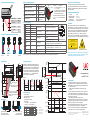
Bedien- und Anzeigeelemente
LED State Farbe LED Output
Select-Taste
LED state
LED
output
Die Taste Select ist ab Werk
- nur mit den Funktionen Reset und
Teachen belegt,
- nur 5 Minuten nach dem Einschalten
der Betriebsspannung aktiv. Danach
wird sie automatisch gesperrt.
Über das Webinterface kann die Funk-
tion Mastern auf die Taste übertragen
werden.
Messobjekt im Messbereich grün
Messwertausgang
RS422
Messobjekt in Messbereichsmitte gelb
Messwertausgang
abgeschaltet
Fehler – z.B. Messobjekt außerhalb des
Messbereichs, zu niedrige Reflexion
rot
Messwertausgang
Strom 4 ... 20 mA
Laser abgeschaltet aus
Sensor aus, keine
Versorgung
Anschlussbelegung
Pin PCF1420-x/I Erläuterung Bemerkung, Beschaltung
12
9
8
7
1
2
3
4
5
6
11
10
Lötseite Kabelbuchse
3 grün RS422 Rx+
Serieller Eingang Intern mit 120 Ohm abgeschlossen
4 gelb RS422 Rx-
5 grau RS422 Tx+
Serieller Ausgang Am Empfänger mit 120 Ohm abschließen
6 rosa RS422 Tx-
7 rot +U
B
Betriebsspannung 11 ... 30 VDC, typ. 24 VDC, P < 2 W
8 schwarz Laser on/off
Schalteingang
Laser aktiv, wenn Eingang mit GND ver-
bunden ist
9 violett Funktionseingang Trigger, Zero/Master, Teachen
10 braun Error Schaltausgang
I
max
= 100 mA, U
max
= 30 VDC
Schaltverhalten programmierbar: (NPN, PNP, Push-Pull)
11 weiß I
OUT
4 ... 20 mA
R
Bürde
= 250 Ohm ergibt U
OUT
1 ... 5 V bei U
B
> 11 V
R
Bürde
= 500 Ohm ergibt U
OUT
2 ... 10 V bei U
B
> 17 V
12 blau GND Bezugsmasse Versorgungs- und Signalmasse
Schirm Steckergehäuse Sensorgehäuse Mit Potentialausgleich verbinden
Die Abschirmung des Kabels ist mit dem Sensorgehäuse verbunden. Das Sensorkabel ist nicht schleppkettentauglich. Einseitig ist es am
Sensor angegossen, das andere Ende besitzt Litzen mit Aderendhülsen oder ein Pigtail mit M12 Steckverbinder.
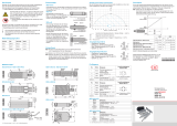
Messbereich, Messbereichsanfang
MBAMB
optoNCDT
Stromausgang Digitalwert
3 mA 262077
4 mA (MBA) 643
12 mA (MBM) 32760
20 mA (MBE) 64877
3 mA 262078
Sensoranordnung bei Bohrungen und Kanten
Ausrichtung
Wand
Drehendes
Objekt
Vertiefung Farb-
wechsel
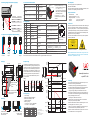
Maßzeichnung
Bereich, welcher von fremden
Lichtquellen und/oder deren
Reflexionen, Spiegelungen frei
zu halten ist.
Grenzen für frei zu
haltenden Bauraum
Laserstrahl
10
3 A
MBAMB
30
20
8
7,50
46
40
8
2,70
2
Y
6
Befestigung
0,5 Nm
min 5
min 4,8
1,0 Nm
Scheibe A2,2; ISO 7089 - A2 Scheibe A3,2; ISO 7089 - A2
M2 x 25; ISO 4762-A2 M3; ISO 4762-A2
Durchsteckverschraubung Direktverschraubung
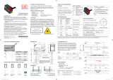
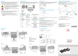
Ausgangsskalierung
Das Teachen skaliert den Analogausgang. Damit
optimieren Sie die Auflösung des Analogausgangs.
Das Verhalten des Strom- und Schaltausgangs ver-
ändert sich. Es werden immer 2 Punkte geteacht,
die den Anfang und das Ende des neuen Messbe-
reichs kennzeichnen. Das Teachen erfolgt über die
eingebaute Taste Select, den Multifunktionsein-
gang oder über das Webinterface.
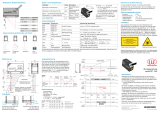
Ablauf:
Werkseinstellung
- Stromausgang
- Messwertmittelung: Median 9
- Messrate: 2 kHz
- Schnittstelle: 921,6 kBps
- Messbereich:
100 % d.M.: I = 20 mA, digital 64877
0 % d.M.: I = 4 mA, digital 643
MBA MBE
20 mA
4 mA
3 mA
64877 65520 2620786430262077
Analog-
ausgang
Messbereich
Digitalwert
LED State
Schalt-
ausgang
Schalt-
ausgang
Standard-Kennlinie
Messobjekt im
Messbereich
MBA MBE
20 mA
4 mA
3 mA
Analog-
ausgang
26207849635262077
Digitalwert
Benutzerdefinierte
Kennlinie
Teach 2 Teach 1
20240
Fehler
LED State
Messobjekt
Messobjekt im Messbereich
Fehler
FehlerFehler
LED State
Messung
Grün, rot, gelb, je
nach Messobjekt-
position
Farbe nach
Messobjekt-
position
rot blinkend
ca. 2 Hz
grün blinkend
ca. 2 Hz
Taste
Select
Messobjekt
positionieren
(4mA-Punkt)
Messobjekt
positionieren
(20mA-Punkt)
Taste
Select
Taste
Select
Messen
rot
t
0
5 min 2 s 30 s 30 st
1
t
2
t
3
t
4
t
6
t
7
t
8
t
5
gelb gelb
min.
30 ms
min.
30 ms
Modell ILD 1420- 10 25 50 100 200 500
MB mm 10 25 50 100 200 500
MBA mm 20 25 35 50 60 100
MBE mm 30 50 85 150 260 600
Y mm 10 21 28 46 70 190
MB = Messbereich
MBA = Messbereichsanfang
MBM = Messbereichsmitte
MBE = Messbereichsende
d.M. = des Messbereichs

Assembly Instructions
optoNCDT 1420
Warnings
Avoid unnecessary laser exposure to the human body. Turn off
the sensor for cleaning and maintenance.
Connect the power supply and the display/output device in
accordance with the safety regulations for electrical equipment.
The power supply may not exceed the specified limits.
> Danger of injury, damage to or destruction of the sensor
Avoid shock and vibration to the sensor. Avoid continuous expo-
sure to fluids. Avoid contact with aggressive materials (washing
agent, penetrating liquids or similar).
> Damage to or destruction of the sensor
Mount the sensor only to the existing holes on a flat surface.
Clamps of any kind are not permitted.
Attach the cable load-free, hold the cable after appr. 25 cm and
hold the pigtail on the connector e.g. zip tie.
Caution - use of controls or adjustments or performance of pro-
cedures other than those specified may cause harm.
Read the instruction manual before using the sensor. The manu-
al is available online or on the supplied CD.
CE Compliance
The following applies to the optoNCDT1420:
EU directive 2014/30/EU
The sensor fulfills the specification of the EMC requirements, if the
instructions in the operating manual are followed.
Proper Environment
- Protection class: IP 65
- Operation temperature: 0 ... 50 °C
- Storage temperature: -20 ... 70 °C
- Humidity: 5 - 95 % (non-condensing)
- Pressure: atmospheric pressure
Laser Class
The sensors operate with a semiconductor laser with a wavelength
of 670 nm (visible/red). The laser is operated in pulse mode, the
maximum optical power is ≤ 1 mW. The pulse frequency depends
on the adjusted measuring rate. The pulse duration of the laser is
regulated depending on the measuring rate and reflectivity of the
target and can be 0.3 up to 3999.6 μs.
The sensors are classified for Laser Class 2 (II). Laser operation is
indicated by LED state.
LASER RADIATION
DO NOT STARE INTO BEAM
CLASS 2 LASER PRODUCT
IEC 60825-1: 2014
P 1mW; =670nm
COMPLIES WITH 21 CFR 1040.10 AND 1040.11
EXCEPT FOR CONFORMANCE WITH IEC 60825-1
ED. 3., AS DESCRIBED IN
LASER NOTICE NO. 56, DATED MAY 8, 2019.
Laser label on sensor cable Warning label on sensor
Read the detailed instruction manual before using the sensor. The
manual is available online on www.micro-epsilon.com/download/
manuals/man--optoNCDT-1420--en.pdf.
Control and Indicator Elements
LED State Color LED Output
Select key
LED state
LED
output
By factory default the key Select is
- programmed with the functions
Reset and Teaching.
- only active for the first 5 minutes
after power up. After that it will be
automatically locked.
The function Masters can be
transferred to the key via the web
interface.
Measuring object within sensor range green RS422 output
Mid range yellow
Measuring value output
off
Error - e.g. Poor target or out of range red
Current output
4 ... 20 mA
Laser off off Sensor off, no supply
Pin Assignment
Pin PCF1420-x/I Description Specification
12
9
8
7
1
2
3
4
5
6
11
10
Solder pin side female
cable connector
3 green RS422 Rx+
Serial input Internally terminated with 120 Ohm
4 yellow RS422 Rx-
5 gray RS422 Tx+
Serial output Terminate externally with 120 Ohm
6 pink RS422 Tx-
7 red +U
B
Power up 11 ... 30 VDC, typ. 24 VDC, P < 2 W
8 black Laser on/off
Switch input
Laser is active, if input is connected
with GND
9 violet Functional input Trigger, Zero/Master, Teaching
10 brown Error Switch output
I
max
= 100 mA, U
max
= 30 VDC,
Programmable switching characteristic: (NPN, PNP, Push-Pull)
11 white I
OUT
4 ... 20 mA
R
Load
= 250 Ohm: U
OUT
1 ... 5 V with U
B
> 11 V
R
Load
= 500 Ohm: U
OUT
2 ... 10 V with U
B
> 17 V
12 blue GND Ground potential Supply and signal ground
Shield Connector housing Sensor housing Connect with potential equalization
The shield of the cable is connected with the housing of the sensor. The sensor cable is not cable carriers suitable. One end is molded on
the sensor, the other end has free leads with ferrules or a pigtail with a M12 male connector.
Measuring Range, Start of Measuring Range
SMR MR
optoNCDT
Current output Digital value
3 mA 262077
4 mA (SMR) 643
12 mA (MMR) 32760
20 mA (EMR) 64877
3 mA 262078
Proper Sensor Arrangement to Avoid Shadowing
Alignment
to a wall
Turning
object
Indentation
Color
change
Drawings
Keep this area free from
other light sources and/or
their reflections
Limits for free
space
Laser beam
10
(.39)
3
(.12)
A
SMRMR
30 (1.18)
8
(.31)
7.50
(.3)
20 (.79)46 (1.81)
40 (1.57)
8
(.31)
2.70
(.11)
2
(.08)
Y
6
(.24)
Mounting
0.5 Nm
min 5
min 4.8
1.0 Nm
Washer A2.2; ISO 7089 - A2 Washer A3.2; ISO 7089 - A2
M2 x 25; ISO 4762-A2 M3; ISO 4762-A2
Bolt connection Direct fastening
Output Scaling
The teaching scales the analog output (4 to 20 mA)
for a part of the measuring range. This allows you to
optimize the resolution for the analog measurement
range. Only the current and switching output will be
affected by the 2 point calibration. Therefore you de-
fine a new start and end for the measurement range.
This teaching procedure can be performed live via
the select key, via the multifunctional input or via
the web interface.
Timing:
Factory Setting
- Current output
- Measurement averaging: Median 9
- Measurement frequency: 2 kHz
- Interface: 921.6 kBps
- Measuring range:
100 % FSO: I = 20 mA , digital 64877
0 % FSO: I = 4 mA, digital 643
Type ILD 1420- 10 25 50 100 200 500
MR mm 10 25 50 100 200 500
SMR mm 20 25 35 50 60 100
EMR mm 30 50 85 150 260 600
Y mm 10 21 28 46 70 190
SMR EMR
20 mA
4 mA
3 mA
64877 65520 2620786430262077
Analog
output
Measuring range
Digital value
LED State
Switching
output
Switching
output
Default characteristic
Measuring object
within range
SMR EMR
20 mA
4 mA
3 mA
Analog
output
26207849635262077
Digital value
User defined characteristic
Teach 2 Teach 1
20240
Error
LED State
Measuring object
Measuring object within range
Error
ErrorError
LED State
Measuring
Green, red, yellow,
depends on
measuring position
Color accord-
ing to meas-
uring position
flashes red
approx. 1 Hz
flashes green
approx. 1 Hz
Key
select
Position the
measuring
object to 4 mA
Position the
measuring
object to 20 mA
Key
select
Key
select
Measuring
red
t
0
5 min 2 s 30 s 30 st
1
t
2
t
3
t
4
t
6
t
7
t
8
t
5
yellow yellow
min.
30 ms
min.
30 ms
MR = Measuring range
SMR = Start of measuring range
MMR = Midrange
EMR = End of measuring range
FSO = Full scale output
-
 1
1
-
 2
2


MICRO-EPSILON optoNCDT 1420 Assembly Instructions
- Typ
- Assembly Instructions
in anderen Sprachen
- English: MICRO-EPSILON optoNCDT 1420
Verwandte Artikel
-
 MICRO-EPSILON optoNCDT 1420 CL1 Assembly Instructions
-
 MICRO-EPSILON optoNCDT 1320 Assembly Instructions
-
 MICRO-EPSILON optoNCDT ILR 103x Bedienungsanleitung
-
 MICRO-EPSILON mainSENSOR MDS-35/-45 Assembly Instructions
-
 MICRO-EPSILON ODC1200 Benutzerhandbuch
-
 MICRO-EPSILON mainSENSOR MDS-40-MK Assembly Instructions


