Seite wird geladen ...

Titel
Montageanleitung
Assembly Instructions
mainSENSOR
MDS-45
MDS-35
MDS-40-D18
MICRO-EPSILON MESSTECHNIK GmbH & Co. KG
Koenigbacher Str. 15 94496 Ortenburg / Germany
Tel. +49 8542 / 168-0 / Fax +49 8542 / 168-90
e-mail info@micro-epsilon.com
www.micro-epsilon.com
X977X369-A022060SWE
*X977X369-A02*
Warnhinweise
Schließen Sie die Spannungsversorgung und das Anzeige-/Ausgabegerät
nach den Sicherheitsvorschriften für elektrische Betriebsmittel an.
Versorgungsspannung darf angegebene Grenzen nicht überschreiten.
> Verletzungsgefahr, Beschädigung oder Zerstörung des Sensors.
Das Magnetfeld der Neodym- und Samarium-Magnete ist sehr
stark und weitreichend. Zu den gefährdeten Geräten gehören
u. a. Fernseher, Monitore, Kredit- und EC-Karten, Computer,
Disketten, Datenträger, Videobänder, Hörgeräte und
Herzschrittmacher.
> Verletzungsgefahr, Beschädigung oder Zerstörung sensiti-
ver Geräte
Vermeiden Sie Stöße und Schläge auf den Sensor. Vermeiden Sie im unge-
steckten Zustand die Einwirkung von Spritzwasser auf den Sensor.
> Beschädigung oder Zerstörung des Sensors
i
Ferromagnetische Mineralien sowie Magnetfelder im Bereich des
Sensorsystems beeinflussen die Kennlinie des Sensors.
Der Messbereich kann sich dadurch verkürzen beziehungsweise
verlängern.
Maße Befestigungsmuttern
Sensor SW Gewinde Höhe
M12 SW19 M12x1 4 mm
M18 SW27 M18x1 4 mm
M30 SW36 M30x1,5 4 mm
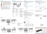
Maßzeichnungen
1
MDS-45-M18-SA / MDS-45-M18-HP-SA
ø15,4f7
Stecker
M18x1
13
46
49
SW16
O-Ring ø14x1
10
Stecker
M8x1
MDS-45-M18-SA (01)
12
10
Stecker M12x1
SW16
15,4f7
46
49
Stecker
M18x1
MDS-40-D18
Stecker
M12x1
53,55
63,55
ø 18
MDS-45-M12-CA / MDS-35-M12-CA-HT
4,5
ø10,5
ø10,5
Kabel ca. ø3,2
(HT: ø3,5)
55
6
(HT: 7)
Stecker
M12x1
1) Abmessungen in mm, nicht maßstabsgetreu
Sensormontage
MDS-40-D18
Umfangsklemmung. Die Montage der MDS-40-D18 erfolgt durch Umfangs-
klemmung; die Halterung und die dazugehörige Schraube müssen nicht-fer-
romagnetisch sein.
MDS-45-K
Montageplatte. Die Montage der
MDS-45-K erfolgt durch Montageplatte; die
Platte und die dazugehörige Schrauben
müssen nicht-ferromagnetisch sein.
Montageplatte
(nicht ferromagnetisch)
MDS-xx-M
Nicht-bündig. Montieren Sie den Sensor
durch das Gewinde M12x1 in der dafür
vorgesehenen Montageplatte und fixieren
den Sensor durch die beiden mitge-
lieferten Muttern auf beiden Seiten der
Montageplatte.
Sensor
Mutter
Montageplatte
(nicht ferromagnetisch)
Bündig. Schrauben Sie dazu den Sensor
soweit in die Montageplatte, bis er bündig
mit der zum Target gewandten Seite
abschließt. Fixieren Sie nun den Sensor
an der gegenüberliegenden Seite der
Montageplatte mit einer der mitgelieferten
Muttern.
Sensor
Mutter
Montageplatte
(nicht ferromagnetisch)
Montage Magnet
Montieren Sie den Magneten durch eine Senkkopfschraube
(nicht magnetisierbar) an dem Messobjekt.
Der Magnet ist zum Schutz beim Transport mit einer Abschirmung versehen.
Entfernen Sie diese vor der Montage. Schieben Sie hierzu zunächst die
beiden Scheiben seitlich vom Magneten. Drücken Sie anschließend
den Magneten aus dem Ring. Beachten Sie bitte bei der Montage des
Magneten die Vorsichtsmaßnahmen.
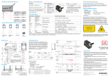
Montage zweier Systeme nebeneinander
Bei der Montage zweier Systeme nebeneinander empfehlen wir, die in der
Grafik angegebenen Abstände einzuhalten.
-1
0
1
2
3
4
5
6
7
-7 -6 -5 -4 -3 -2 -1 0 1 2 3 4 5 6 7
Abstand y [Vielfache des MB]
Abstand x [Vielfache des MB]
Grenzlinie für Messbereichsende 1. Sensor (Fehler < ±0,5 %)
Magneten benachbarter Sensoren
Einflussbereich Sensor / Magnet 1 Abweichung > ±0,5 %
MB = Messbereich
Messobjekt Magnet MB 45
- Oberfläche: vernickelt
- Befestigung: Senkkopfschraube M4
- Max. Einsatztemperatur: 80 °C (150 °C)
- Gewicht: ca. 15 g
5
ø20
±1
ø4,3
Messobjekt Magnet MB 35 HT
- Oberfläche: unbeschichtet
- Befestigung: Senkkopfschraube M5
- Max. Einsatztemperatur: 200 °C (250 °C)
- Gewicht: ca. 15 g
ø5,2
6
ø22
±1
MDS-45-M12-SA / MDS-45-M12-SA-HT
60
45,25
9,75
61
Stecker
M12x1
ø10,5
ø10,5
M12x1
Stecker
MDS-45-M30-SA
SW27
Stecker
M8x1
59
46
10
13
M30x1,5
MDS-45-K-SA
33
23
8,3
6
11,8
ø6,5
ø3,5
57,8
51
5,1
Stecker
M8x1
Pin-Belegung
Pin PC5/4 Belegung
Anschlussbelegung
Stecker M8x1
1 braun
Versorgungsspannung
11,5 V ... 30 V
2
1
4
3
4-pol. Kabelbuchse M8x1
Ansicht Lötseite
2 weiß
Analogausgang
4 mA ... 20 mA / n.c.
3 blau Masse
4 schwarz Analogausgang 2 V ... 10 V
Schirm
Schirm mit Erde verbinden
1
Pin PC5/5 Belegung
Anschlussbelegung
Stecker M12x1
1 braun Versorgungsspannung
2 1
3 4
4-pol. Kabelbuchse M12x1
Ansicht Lötseite
2 weiß
Analogausgang
4 mA ... 20 mA / n.c.
3 blau Masse
4 schwarz Analogausgang 2 V ... 10 V
5 grau Nicht belegt
Schirm
Schirm mit Erde verbinden
1
MDS-45-M12-CA
Farbe Belegung
Braun Versorgungsspannung 11,5 ... 30 V
Weiß Analogausgang 4 .. 20 mA / n.c.
Blau Masse
Schwarz Analogausgang 2 ... 10 V
Schirm Schirm mit Erde verbinden
1
MDS-35-M12-CA-HT
Farbe Belegung
Rot Versorgungsspannung
- Analogausgang 4 ... 20 mA / n.c.
Blau Masse
Schwarz Analogausgang 2 ... 10 V
Schirm Schirm mit Erde verbinden
1
1) Bei Metallsensoren mit Gehäuse verbunden
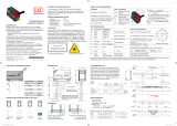
Sensorsignal
Durch die Anpassung des Messbereichsanfangs kann der Sensor auf den
nominellen Ausgangswert (2 V) eingestellt werden. Vor dieser Anpassung ist
sicherzustellen, dass der Sensor mindestens 10 Minuten in Betrieb ist.
Führen Sie nun den Magneten zur Minimalposition.
Verschieben Sie den Sensor so, dass das Ausgangssignal den nomi-
nellen Wert anzeigt. Fixieren Sie den Sensor in dieser Position gemäß
nebenstehender Montageanweisung.
MBA MB
MBE,
siehe Tabelle
MBA,
siehe Tabelle
MBA MBE
mA V mm mA V
MDS-45-M30-SA / MDS-45-K-SA 4 ±0,4 2 ±0,2 4 19,2 ±0,8 9,6 ±0,4
MDS-40-D18 4 ±0,8 2 ±0,4 1,5 19,2 ±0,8 9,6 ±0,4
MDS-45-M18-SA / MDS-45-M18-SA(01) /
MDS-45-M18-HP-SA
- 2 ±0,3 2,25 - 9,6 ±0,4
MDS-45-M12-CA / MDS-45-M12-SA - 2 ±0,3 5 - 9,6 ±0,4
MDS-35-M12-CA-HT / MDS-35-M12-SA-HT - 2 ±0,4 1 - 9,6 ±0,4
Werte für Standardmagnete aus Lieferumfang

Warnings
Connect the power supply and the display/output device according to the
safety regulations for electrical equipment.
The supply voltage must not exceed the specified limits.
> Risk of injury, damage to or destruction of the sensor.
The magnetic field of the neodymium magnets and samarium
is very strong and farreaching. The critical units are amongst
other things, television, monitors, credit and EC cards, PCs,
floppy disks, data processing media, videotapes, acoustic
hearing apparatus and cardiac pacemaker.
> Danger of injury, damage to or destruction of sensitive
devices
Avoid shocks and impacts to the sensor. Avoid continuous exposure to fluids,
when disconnected.
> Damage to or destruction of the sensor
i
Ferromagnetic material, as well as the magnetic field in the area of sen-
sor systems affect the sensor characteristics. Therefore, the measuring
range reduces or increases.
Ground Fixing Nuts
Sensor WS Thread Height
M12 SW19 M12x1 4 mm
M18 SW27 M18x1 4 mm
M30 SW36 M30x1,5 4 mm
Dimensional Drawings
1
MDS-45-M18-SA / MDS-45-M18-HP-SA
O-Ring ø14x1
ø15.4f7
Connector
M18x1
13 (.51)
46 (1.8)
49 (1.9)
WS16
10
(.39)
Connector
M8x1
MDS-45-M18-SA (01)
12
(.47)
10
(.39)
Connector M12x1
WS16
15.4f7
46 (1.8)
49 (1.9)
Connector
M18x1
MDS-40-D18
Connector
M12x1
53.55 (2.10)
63.55 (2.50)
ø18 (.71 dia.)
Sensor Mounting
MDS-40-D18
Circumferential Clamping. The MDS-40-D18 is mounted by means of
circumferential clamping; The mounting and the associated screw must be
non-ferromagnetic.
MDS-45-K
Mounting plate. The MDS-45-K is mounted
by means of the mounting plate; the
plate and the associated screws must be
non-ferromagnetic.
Mounting plate
(non-ferromagnetic)
MDS-xx-M
Non-flush mounting. Mount the sensor
through the M12x1 thread in the mounting
plate provided for this purpose and fix the
sensor on both sides of the mounting plate
by means of the two nuts delivered.
Sensor
Screw
Mounting plate
(non-ferromagnetic)
Flush mounting. For this purpose, screw
the sensor into the mounting plate as far
as it ends flush with the side facing the
target. Now fix the sensor on the opposite
side of the mounting plate using one of the
nuts delivered.
Sensor
Screw
Mounting plate
(non-ferromagnetic)
Magnet Mounting
Mount the magnet on the measuring object using the counter sunk
screw (not magnetizable).
In order to protect the sensor during shipment the magnet is provided with a
shielding.
Remove the shielding before mounting. To do so, please push the layers
laterally from the magnet. Afterwards, please press the magnet out of
the ring. Please carefully adhere to the precautions during mounting the
magnet.
Mounting of Two Systems Next to Each Other
Please adhere to the distances stipulated in the graphic for the mounting of
two systems.
-1
0
1
2
3
4
5
6
7
-7 -6 -5 -4 -3 -2 -1 0 1 2 3 4 5 6 7
Position y [Multiple of the MR]
Distance x [Multiple of MR]
Limit line for end of measuring range 1. sensor (error < ±0.5 %)
Magnets of neighbouring sensors
Sphere of influence sensors / magnet 1 influence > ±0.5 %
MR = Measuring range
Measuring object magnet MB 45
- Surface: nickel-plated
- Fixing: counter sunk screw M4
- Max. operation temperature:
80 °C/176 °F (150 °C/302 °F)
- Weight: approx. 15 g
5
ø20
±1
ø4.3
Measuring object magnet MB 35 HT
- Surface: uncoated
- Fixing: counter sunk screw M5
- Max. operation temperature:
200 °C/392 °F (250 °C/482 °F)
- Weight: approx. 15 g
ø5.2
6
ø22
±1
MDS-45-M12-CA / MDS-35-M12-CA-HT
4.5 (.18)
ø10.5
(.41 dia.)
ø10.5 (.41 dia.)
Cable approx.
ø3.2 (.13 dia.)
(HT: ø3.5 (.14 dia.))
55 (2.17)
6
(HT: 7)
Connector
M12x1
MDS-45-M12-SA / MDS-45-M12-SA-HT
60 (2.36)
45.25 (1.78)
9.75
61 (2.40)
60 (2.36)
Connector
M12x1
ø10.5 (.41 dia.)
ø10.5
(.41 dia.)
Connector
M12x1
(.38)
MDS-45-M30-SA
SW27
Connector
M8x1
59 (2.32)
46 (1.81)
10 (.39)
13 (.51)
M30x1.5
MDS-45-K-SA
33 (1.3)
23 (.91)
8.3 (.33)
6 (.23)
11.8
(.46)
ø6.5
(.26 dia.)
(.14 dia.)
57.8 (2.28)
51 (2)
Connector
M8x1
5.1 (.2)
ø3.5
Pin Assignment
Pin PC5/4 Assignment
Pin assignment
connector M8x1
1 brown Supply voltage 11.5 V ... 30 V
2
1
4
3
4-pin female cable
connector M8x1,
solder pin side
2 white Analog output 4 mA ... 20 mA / n.c.
3 blue Ground
4 black Analog output 2 V ... 10 V
Shield
Connect the shield to the earth
1
Pin PC5/5 Assignment
Pin assignment
connector M12x1
1 brown Supply voltage
2 1
3 4
4-pin female cable
connector M12x1,
solder pin side
2 white Analog output 4 mA ... 20 mA / n.c.
3 blue Ground
4 black Analog output 2 V ... 10 V
5 gray Not assigned
Shield
Connect the shield to the earth
1
MDS-45-M12-CA
Color Assignment
brown Supply voltage 11.5 V ... 30 V
white Analog output 4 mA ... 20 mA / n.c.
blue Ground
black Analog output 2 V ... 10 V
Shield
Connect the shield to the earth
1
MDS-35-M12-CA-HT
Color Assignment
red Power supply
- Analog output 4 mA ... 20 mA / n.c.
blue Ground
black Analog output 2 V ... 10 V
Shield
Connect the shield to the earth
1
1) In the case of metal sensors connected with housing
1) Dimensions in mm (inches), not to scale
Sensor Signal
The sensor can be set to a nominal output value (2 V) if the start of measuring
range is adjusted. Ensure that the sensor has been in operation for at least 10
minutes before making adjustments.
Please move the magnet to the minimum position. Move the sensor in
such a way that the output signal displays the nominal value.
Finally, please fix the sensor in this position according to the installation
instructions mentioned above.
SMR MR
EMR,
see table
SMR,
see table
SMR EMR
mA V mm mA V
MDS-45-M30-SA / MDS-45-K-SA 4 ±0.4 2 ±0.2 4 19.2 ±0.8 9.6 ±0.4
MDS-40-D18 4 ±0.8 2 ±0.4 1.5 19.2 ±0.8 9.6 ±0.4
MDS-45-M18-SA / MDS-45-M18-SA(01) /
MDS-45-M18-HP-SA
- 2 ±0.3 2.25 - 9.6 ±0.4
MDS-45-M12-CA / MDS-45-M12-SA - 2 ±0.3 5 - 9.6 ±0.4
MDS-35-M12-CA-HT / MDS-35-M12-SA-HT - 2 ±0.4 1 - 9.6 ±0.4
Values for standard magnets from the scope of delivery
1/2