MICRO-EPSILON mainSENSOR MDS-40-MK Assembly Instructions
- Typ
- Assembly Instructions

Titel
Montageanleitung
Assembly Instructions
mainSENSOR
MDS-40-MK
MICRO-EPSILON MESSTECHNIK GmbH & Co. KG
Koenigbacher Str. 15
94496 Ortenburg / Germany
Tel. +49 8542 / 168-0 / Fax +49 8542 / 168-90
e-mail [email protected]
www.micro-epsilon.com
X977X334-A032060SWE
*X977X334-A03*
Warnhinweise
Schließen Sie die Spannungsversorgung und das Anzeige-/Ausgabegerät
nach den Sicherheitsvorschriften für elektrische Betriebsmittel an.
Versorgungsspannung darf angegebene Grenzen nicht überschreiten.
> Verletzungsgefahr, Beschädigung oder Zerstörung des Sensors.
Das Magnetfeld der Neodym- und Samarium-Magnete ist sehr
stark und weitreichend. Zu den gefährdeten Geräten gehören
u. a. Fernseher, Monitore, Kredit- und EC-Karten, Computer,
Disketten, Datenträger, Videobänder, Hörgeräte und
Herzschrittmacher.
> Verletzungsgefahr, Beschädigung oder Zerstörung sensiti-
ver Geräte
Vermeiden Sie Stöße und Schläge auf den Sensor. Vermeiden Sie im unge-
steckten Zustand die Einwirkung von Spritzwasser auf den Sensor.
> Beschädigung oder Zerstörung des Sensors
i
Ferromagnetische Materialien sowie Magnetfelder im Bereich des
Sensorsystems beeinflussen die Kennlinie des Sensors.
Der Messbereich kann sich dadurch verkürzen beziehungsweise
verlängern.
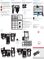
Sensormontage
Die Montage des Sensors erfolgt mit Hilfe von Zylinderkopfschrauben M3
(nicht magnetisierbar). Das Kabel muss in Steckernähe entsprechend den
Umgebungsbedingungen ausreichend gesichert sein.
Montagefläche
(nicht ferromagnetisch)
Montage mit Kabelbindern auf zylindrischen Objekten
Mit Hilfe der optionalen Halteplatte kann der Sensor auf einem zylindrischen
Objekt befestigt werden.
Montage Magnet
Montieren Sie den Magnet durch eine geeignete Schraube
(nicht ferromagnetisch) am Messobjekt.
Abhängig von der Verpackungseinheit wird der Magnet beim Transport mit
einer Abschirmung versehen.
Entfernen Sie diese bei der Montage, indem Sie hierzu zunächst die
beiden Scheiben seitlich vom Magneten schieben.
Drücken Sie anschließend den Magneten aus dem Ring.
i
Beachten Sie bei der Montage des Magneten die
Vorsichtsmaßnahmen.
Hauptmessrichtung
Die technischen Daten im Katalog beziehen sich auf die Hauptmessrichtung.
Es sind jedoch auch andere Magnetanordnungen und Bewegungsrichtungen
möglich, was eine Änderung der Kennlinie zur Folge haben kann.
2
9
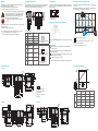
Anschlussbelegung
Pin
PC5/4(01)
PC5/4/90(01)
Beschreibung PIN-Belegung Option SA8
1 braun + Versorgung
2
1
4
3
4-pol.Kabelbuchse M8x1,
Ansicht Lötseite
2 weiß GND Out
3 blau GND Versorgung
4 schwarz + Out
Pin
PC1/4-SR0
PC1/4-SR7
Beschreibung PIN-Belegung Option SR7
1 braun + Versorgung
1 2 3 4
PIN-Belegung Option SR0
1 2 3 4
4-pol. Platinenstecker,
Ansicht Lötseite
2 weiß GND Out
3 blau GND Versorgung
4 schwarz + Out
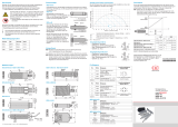
Montage zweier Systeme nebeneinander
Bei der Montage zweier Systeme nebeneinander sind die in der Grafik ange-
gebenen Abstände einzuhalten.
Beispiel (Grafik): Magnet RL21 (SrFe); bei anderen Magneten ändern sich die
Abstände in Abhängigkeit von der Magnetgröße und -stärke.
Position x / mm
Position y / mm
0
0
MBE
180
200
225
Magneten benachbarter Sensoren
Einflussbereich Sensor / Magnet 1 Abweichung > ±0,5 %
MBE = Messbereichsende
Abmessungen in mm, nicht maßstabsgetreu
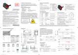
Maßzeichnungen
Option SA8
27,4
ø8,6
19,9
11,3
13,05
12,45
8,25
165°
M8
36,85
30,25
24,55
4xR0,5
17,4
21,4
6,5
6,5
3
23,3
2
28,3
14,65
2,8
13,4
(2x)ø3,4
165°
4
2,5
2
Option SR7 Option SR0
3
23,3
(2x)ø3,4
17,45
25,85
27,4
17,4
21,4
11
13,05
12,45
6,5
6,5
21,45
8,25
11,3
4
165°
2,5
165°
19,9
13,4
24,55
28,3
14,65
2,8
2
2
17,4
21,4
165°
13,05
12,45
6,5
2,5
4
4xR0,5
165°
2
2
(2x)ø3,4
27,4
19,9
14,65
2,8
24,55
13,4
3
23,3
28,3
6,5
8,25
11,3
14,9
24,9
Sensorsignal (Magnet RL21)
MBA
MB
MBE,
siehe Tabelle
MBA,
siehe Tabelle
-F -U45R -U10 -I
MBA
402 Hz 0,5 V 2 V 4 mA
±6 Hz ±0,2 V ±0,4 V ±0,8 mA
1,5 mm 1,5 mm 1,5 mm 1,5 mm
MBE
285 HZ 4,5 V 9,6 V 19,2 mA
±6 Hz ±0,2 V ±0,4 V ±0,8 mA
Optionale Halteplatte nicht im
Lieferumfang der Vorzugstypen
enthalten.
Abmessungen in mm,
nicht maßstabsgetreu

Warnings
Connect the power supply and the display/output device according to the
safety regulations for electrical equipment.
The supply voltage must not exceed the specified limits.
> Risk of injury, damage to or destruction of the sensor.
The magnetic field of the neodymium magnets and samarium
is very strong and farreaching. The critical units are amongst
other things, television, monitors, credit and EC cards, PCs,
floppy disks, data processing media, videotapes, acoustic
hearing apparatus and cardiac pacemaker.
> Danger of injury, damage to or destruction of sensitive
devices
Avoid shocks and impacts to the sensor. Avoid continuous exposure to fluids,
when disconnected.
> Damage to or destruction of the sensor
i
Ferromagnetic material, as well as the magnetic field in the area of
sensor systems affect the sensor characteristics.
Therefore, the measuring range reduces or increases.
Sensor Mounting
The sensor is mounted using cylinder head screws M3 (not ferromagnetic).
The cable must be secured adequately near the connector according to the
ambient conditions.
Mounting surface
(not ferromagnetic)
Mounting with Cable Ties on Cylindrical Targets
Using an optional retaining plate the sensor can be mounted on a cylindrical
target.
Magnet Mounting
Mount the magnet on a measuring object using an adequate screw
(not ferromagnetic).
Depending on the packaging unit, the magnet is provided with a shielding
(washers) during shipment.
In order to remove the shielding when mounting the sensor, push both
washers laterally from the magnet.
Please press the magnet out of the ring.
i
Please carefully adhere to the warnings during mounting the magnet.
Main Measurement Direction
The technical data in the catalogue refer to the main measurement direction.
However, other magnet arrangements and directions of movement are
possible but can result in a change of the characteristic line.
2 (.08)
9 (.35)
Pin Assignment
Pin
PC5/4(01)
PC5/4/90(01)
Description PIN assignment option SA8
1 brown + Supply
2
1
4
3
4-pin female cable connector M8x1,
solder pin side
2 white GND Out
3 blue GND supply
4 black + Out
Pin
PC1/4-SR0
PC1/4-SR7
Description PIN assignment option SR7
1 brown + Supply
1 2 3 4
PIN assignment option SR0
1 2 3 4
4-pin board connector,
solder pin side
2 white GND Out
3 blue GND Supply
4 black + Out
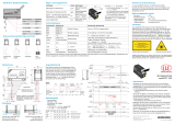
Mounting of Two Systems Next to Each Other
Please adhere to the distances stipulated in the graphic for the mounting of
two systems.
Example (graphic): Magnet RL21 (SrFe); with other magnets, the distances
change depending on the magnet size and strength.
Position x / mm
Position y / mm
0
0
EMR
180 (7.09)
200 (7.87)
225 (8.86)
Magnets of neighbouring sensors
Sphere of influence sensors / magnet 1influence > ±0.5 %
EMR = End of measuring range
Dimensions in mm (inches), not to scale
Dimensional Drawing
Option SA8
27.4 (1.08)
19.9 (.78)
11.3 (.44)
13.05 (.51)
12.45 (.49)
8.25
(.32)
165°
M8
36.85 (1.45)
30.25 (1.19)
24.55 (.97)
4xR0.5
17.4 (.69)
21.4 (.84)
6.5 (.26)
6.5 (.26)
3 (.12)
23.3 (.92)
2 (.08)
28.3 (1.11)
14.65 (.58)
2.8 (.11)
13.4 (.53)
(2x)ø3.4
(.13 dia)
165°
4 (.16)
2.5 (.1)
2 (.08)
ø8.6 (.34 dia)
Option SR7 Option SR0
3 (.12)
23.3 (.92)
(2x)ø3.4
(.13 dia)
17.45 (.69)
25.85 (1.02)
27.4 (1.08)
17.4 (.69)
21.4 (.84)
11 (.43)
13.05 (.51)
12.45 (.49)
6.5 (.26)
6.5 (.26)
21.45 (.84)
8.25 (.32)
11.3 (.44)
4 (.16)
165°
2.5
(.10)
165°
19.9 (.78)
13.4 (.53)
24.55 (.97)
28.3 (1.11)
14.65
(.58)
2.8 (.11)
2 (.08)
2 (.08)
17.4 (.69)
21.4 (.84)
165°
13.05 (.51)
12.45 (.49)
6.5 (.26)
2.5
(.1)
4 (.16)
4xR0.5
165°
2(.08)
2 (.08)
(2x)ø3.4
(.13 dia)
27.4 (1.08)
19.9 (.78)
14.65 (.58)
2.8 (.11)
24.55 (.97)
13.4 (.53)
23.3 (.92)
28.3 (1.11)
6.5 (.26)
8.25 (.32)
11.3 (.44)
14.9 (.59)
24.9 (.98)
3 (.12)
Optional retaining plate not
included in delivery with the
preferred types.
Dimensions in mm (inches),
not to scale
Sensor Signal (Magnet RL21)
SMR
MR
EMR,
see table
SMR,
see table
-F -U45R -U10 -I
SMR
402 Hz 0.5 V 2 V 4 mA
±6 Hz ±0.2 V ±0.4 V ±0.8 mA
1.5 mm 1.5 mm 1.5 mm 1.5 mm
EMR
285 HZ 4.5 V 9.6 V 19.2 mA
±6 Hz ±0.2 V ±0.4 V ±0.8 mA
-
 1
1
-
 2
2


MICRO-EPSILON mainSENSOR MDS-40-MK Assembly Instructions
- Typ
- Assembly Instructions
in anderen Sprachen
- English: MICRO-EPSILON mainSENSOR MDS-40-MK
Verwandte Artikel

Andere Dokumente
-
 Smooth Fitness Motorized Treadmill 8.25E Benutzerhandbuch
-
Xoro MBA 26 Bedienungsanleitung
-
 Bibby Sterilin Stuart SA8 Instructions For Use Manual
-
Danfoss DST X520 Rotary position sensor Installationsanleitung
-
SICK OD Max Displacement Sensor Bedienungsanleitung
-
Husqvarna 125/2002 Benutzerhandbuch
-

