Baumer GAM900 Installation and Operating Instructions
- Typ
- Installation and Operating Instructions

Baumer IVO GmbH & Co. KG
Dauchinger Strasse 58-62 · DE-78056 Villingen-Schwenningen
Phone +49 7720 942-0 · Fax +49 7720 942-900
[email protected] · www.baumer.com
Printed in Germany · 03.20 · 178.51.233/5
· 81108023
DE Originalbetriebs- und Montageanleitung
EN Translation of the original operating and
mounting instructions
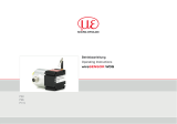
GAM900
Beschleunigungssensor
Acceleration sensor
Elektrischer Anschluss
Beschleunigungssensor elektrisch nicht verändern und keine Verdrahtungsarbeiten
unter Spannung vornehmen. Der elektrische Anschluss darf unter Spannung nicht
aufgesteckt oder abgenommen werden. Bei Verbrauchern mit hohen Störpegeln se-
parate Spannungsversorgung für den Beschleunigungssensor bereitstellen.
Beschleunigungssensor-Gehäuse und Anschlusskabel vollständig schirmen. Die ge-
samte Anlage EMV gerecht installieren. Einbauumgebung und Verkabelung beein-
ussen die EMV des Beschleunigungssensors. Beschleunigungssensor und Zulei-
tungen räumlich getrennt oder in grossem Abstand zu Leitungen mit hohem Störpe-
gel (Frequenzumrichter, Schütze usw.) verlegen. Geschirmte Anschlusskabel ver-
wenden.
- GAM900 mit Kunststoffgehäuse: Kabelschirm steuerungseitig auegen.
- GAM900 mit Aluminiumgehäuse: Kabelschirm beidseitig auegen. Kabelschirm über
Stecker M12 mit Sensorgehäuse verbinden.
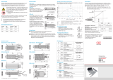
Anschlussbelegung
Stecker 1, Stecker M12, 12-polig
Pin Belegung
Pin 1 GND
Pin 2 Test-Eingang
Pin 3 UB
Pin 4 Analog Masse
Pin 5 Analogausgang X
Pin 6 Analogausgang Y
Pin 7 Relais 1 / Kontakt NO*
Pin 8 CAN Ground
Pin 9 Relais 1 / Kontakt CO*
Pin 10 Relais 1 / Kontakt NC*
Pin 11 CAN Low
Pin 12 CAN High
Stecker 1
Stecker 1 Stecker 2
Stecker 2, Stecker M12, 12-polig
Pin Belegung
Pin 1 Relais 2 / Kontakt CO*
Pin 2 n.c.
Pin 3 n.c.
Pin 4 n.c.
Pin 5 n.c.
Pin 6 n.c.
Pin 7 n.c.
Pin 8 CAN Ground
Pin 9 Relais 2 / Kontakt NO*
Pin 10 Relais 2 / Kontakt NC*
Pin 11 CAN Low
Pin 12 CAN High
* Relaiskonguration kundenspezisch möglich
Montagehinweise
Schläge oder Schocks auf Gehäuse vermeiden. Gehäuse nicht verspannen. Toleranzen
bei der Montage können sich auf den Messwert auswirken.
Den Beschleunigungssensor an den Befestigungsbohrungen mit M4 Schrauben
(1,9 Nm) fest montieren. Koordinatenausrichtung (x-/x+/y-/y+/z-/z+). Insbesondere
bei kundenspezisch kongurierter Tiefpass-Filterung zeigt sich eine schräge Ein-
baulage als Offset im Beschleunigungssignal.
2-Achsen 3-Achsen
–y+x
–x+y
+z
–z
–y+x
–x+y
Befestigungs-
bohrungen
mit M4-
Schrauben
Sicherheitshinweise
Die für die Verwendung bzw. den geplanten Einsatzzweck zutreffenden Ge-
setze, Richtlinien und Normen sind zu beachten.
Ein fehlerhaftes Gerät darf nur mit einem Gerät identischen Typs ausge-
tauscht werden. Ausschlaggebend ist die eindeutige 8-stellige Nummer auf
dem Typenschild („Item“).
Bei Anzeichen von Beschädigung darf das Gerät nicht eingesetzt werden.
Das Gerät darf nicht ausserhalb der im Datenblatt angegebenen Grenzwerte
betrieben werden, welches als Download auf www.baumer.com zur Verfü-
gung steht.
Vor Inbetriebnahme der Anlage alle elektrischen Verbindungen überprüfen.
Montage, elektrischer Anschluss oder sonstige Arbeiten am Beschleuni-
gungssensor und an der Anlage müssen fachgerecht ausgeführt werden.
Eine Gefährdung von Personen, eine Beschädigung der Anlage und eine
Beschädigung von Betriebseinrichtungen durch den Ausfall oder Fehlfunk-
tion des Beschleunigungssensors muss durch geeignete Sicherheitsmass-
nahmen ausgeschlossen werden.
Bestimmungsgemässer Gebrauch
Der Beschleunigungssensor ist ein Präzisionsmessgerät. Er dient zur Erfassung und
Überwachung von Beschleunigungen sowie der Aufbereitung und Bereitstellung von
Messwerten als elektrische Ausgangssignale für das Folgegerät. Den Beschleuni-
gungssensor nur zu diesem Zweck verwenden. Die Funktion des Beschleunigungs-
sensors ist im Datenblatt und dieser Montageanleitung beschrieben. Die Eignung für
den jeweiligen Einsatzzweck ist kundenseitig zu prüfen.
Transport, Lagerung und Entsorgung
Ausschliesslich in Originalverpackung transportieren und lagern.
Beschleunigungssensor nicht fallen lassen – ansonsten ist das Gerät nicht mehr ein-
zusetzen. Bestandteile nach länderspezischen Vorschriften entsorgen.
55 30
9012.5
42
77 6.5
27.5 13
LED
M12x1
ø4.5 (3x)
R5
23
55 30
9012.5
42
77 6.5
13
M12x1
R5
LED
ø4.5 (3x)
23
GAM900 - Aluminiumgehäuse, 2 x Stecker M12
GAM900 - Kunststoffgehäuse, 2 x Stecker M12
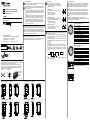
Relais-Funktion
Max. Schaltspannung: 30 V, max. Schaltstrom: 1,5 A.
Das Schalten von induktiven Lasten ist nicht zulässig.
Relais-Kongurationen (z.B. Ansprechschwelle) siehe
Datenblatt oder Handbuch.
Standardbetrieb
Im Standardbetrieb (aktuelle Beschleunigung kleiner
Relais-Ansprechschwelle) gilt:
- Kontakt CO / NO ist geschlossen
- Kontakt CO / NC ist geöffnet
Grenzwertüberschreitung
Bei Überschreiten des Grenzwerts (aktuelle Beschleuni-
gung grösser Relais-Ansprechschwelle) gilt:
- Kontakt CO / NO ist geöffnet
- Kontakt CO / NC ist geschlossen
Spannungsloser Zustand
Im spannungslosen Zustand (ohne Versorgung) gilt:
- Kontakt CO / NO ist geöffnet
- Kontakt CO / NC ist geschlossen
NO
NC
CO
NO
NC
CO
NO
NC
CO
Wartung/Relais-Test
Die Funktion der Relais muss kundenseitig einmal jährlich geprüft und ent-
sprechend dokumentiert werden.
Ansonsten sind innerhalb der Gebrauchsdauer keine Wartungsarbeiten not-
wendig. Die Relaisfunktion kann mittels Test-Eingang oder CANopen Restart
Kommando getestet werden.
Das Schalten der Relaiskontakte muss kundenseitig geprüft werden. Schal-
ten die Relaiskontakte nach der Testinitiierung nicht, muss das Gerät ausge-
tauscht werden.
Test-Eingang
Die Prüfung der Relais-Funktion wird durch zweimaliges Anlegen eines
High-Signals am entsprechenden Pin initiiert. Ein High-Signal muss einen
Signalpegel grösser 70 % der Betriebsspannung vorweisen. Die Signaldau-
er und die Pause zwischen den zwei High-Signalen liegt zwischen 1 und 3
Sekunden.
TTT
>0.7 x UB
1s < T < 3s
Details zur CANopen Kommunikation insbesondere zum Restart Kommando
sind im Handbuch beschrieben.
GAM900 - Aluminiumgehäuse, 1 x Stecker M12
Abmessungen
GAM900 - Kunststoffgehäuse, 1 x Stecker M12
55 30
9012.5
42
77 6.5
27.5 13
M12x1
R5
ø4.5 (3x)
LED
23
55 30
9012.5
42
77 6.5
13M12x1
R
5
23
LED
ø4.5 (3x)

55 30
9012.5
42
77 6.5
27.5 13
LED
M12x1
ø4.5 (3x)
R5
23
55 30
9012.5
42
77 6.5
27.5 13
M12x1
R5
ø4.5 (3x)
LED
23
55 30
9012.5
42
77 6.5
13
M12x1
R5
LED
ø4.5 (3x)
23
55 30
9012.5
42
77 6.5
13M12x1
R
5
23
LED
ø4.5 (3x)
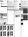
E-connection
Do not perform any electrical modications at the acceleration sensor or any wiring
work while the device is live. Never plug or unplug the electrical connection while the
acceleration sensor is live. Arrange for separate power supply of the acceleration
sensor where working with consumers with high interference emissions.
Completely shield the acceleration sensor and connecting cable. Make sure the en-
tire system is installed in line with EMC requirements. Ambient installations and ca-
bling affect the electromagnetic compatibility of the acceleration sensor. Install acce-
leration sensor and supply cables separately or far away from cables with high inter-
ference emissions (frequency converters, contactors, etc). Use shielded connecting
cables.
- GAM900 in plastic housing: Provide cable shield at the control unit.
- GAM900 in aluminium housing: Provide cable shield on both ends and connect with
sensor housing via M12 connector.
Terminal assignment
Connector 1, M12 connector 12-pin
Pin Assignment
Pin 1 GND
Pin 2 Test input
Pin 3 UB
Pin 4 Analog Ground
Pin 5 Analog output X
Pin 6 Analog output Y
Pin 7 Relay 1 / contact NO*
Pin 8 CAN Ground
Pin 9 Relay 1 / contact CO*
Pin 10 Relay 1 / contact NC*
Pin 11 CAN Low
Pin 12 CAN High
connector 1
connect. 1 connect. 2
Connector 2, M12 connector 12-pin
Pin Assignment
Pin 1 Relay 2 / contact CO*
Pin 2 n.c.
Pin 3 n.c.
Pin 4 n.c.
Pin 5 n.c.
Pin 6 n.c.
Pin 7 n.c.
Pin 8 CAN Ground
Pin 9 Relay 2 / contact NO*
Pin 10 Relay 2 / contact NC*
Pin 11 CAN Low
Pin 12 CAN High
* Customer-specic relay conguration on request
Mounting instructions
Avoid shocks and impacts on the housing as well as any deformation. Mounting tole-
rances may have an inuence on the measured result.
Attach the acceleration sensor rmly (1.9 Nm) at its mounting bores using M4
screws. Proceed with alignment of coordinates (x-/x+/y-/y+/z-/z+). Particularly with
user-specic conguration in deep pass ltering, an inclined mounting position will be
indicated as offset in the acceleration signal.
2-axes 3-axes
–y+x
–x+y
+z
–z
–y+x
–x+y
Mounting
bores with
screws M4
Safety instructions
Observe the legal obligations, directives and standards applicable for the
use respectively intended use.
Only replace a defective by an identical product. The 8-digit reference
number on the product label („item“) is mandatory here.
The device must not be used when presenting any trace of damage.
Do not operate the device beyond the limits specied in the data sheet
available for download at www.baumer.com.
Check all electrical connections prior to commissioning of the installation.
Mounting, installation and e-connection or any other work performed at the
acceleration sensor must be carried out by authorised experts only.
Appropriate safety precautions must be taken to exclude any risk of personal
injury and damage to operating equipment as a result of an acceleration sen-
sor malfunction.
Intended use of the device
The acceleration sensor is a precision instrument. It is intended to detect and monitor
acceleration as well as to evaluate and supply the information in the form of electrical
output signals for the downstream device. The acceleration sensor must not be used
for any other purpose. Functionality is described in the data sheet and this mounting
instruction. The customer is to verify whether the device is suitable for the intended
application task.
Transport, storage and disposal
Only ever transport and store the acceleration sensor in its original packaging.
Never drop the acceleration sensor – otherwise the device must no longer be used.
Dispose of the components observing the legal regulations prevailing in your country.
Dimensions
GAM900 - plastic housing, 1 x M12 connector GAM900 - aluminium housing, 1 x M12 connector
GAM900 - aluminium housing, 2 x M12 connector
GAM900 - plastic housing, 2 x M12 connector
Relay functionality
Max. switching voltage: 30 V
Max. switching current: 1.5 A
Switching of inductive load is not permitted.
Relay conguration (i.e. response threshold) see data
sheet or manual.
Standard operation
In standard operation (present acceleration below
response threshold) applies:
- Contact CO / NO is closed
- Contact CO / NC is open
Out-of-limit
When exceeding the limit (present acceleration beyond
relay threshold) applies:
- Contact CO / NO is open
- Contact CO / NC is closed
Powerless state
In powerless state (without supply) applies:
- Contact CO / NO is open
- Contact CO / NC is closedn
NO
NC
CO
NO
NC
CO
NO
NC
CO
Maintenance/relay test
The customer is to ensure proper relay function by correspondingly docu-
mented tests once a year.
Any other maintenance during the service life of the product is not required.
Proper relay functionality can be tested using the test input or the CANopen
restart command.
Customer is to verify proper switching of the relay contacts. Faulty relay swit-
ching after test initialization would call for device exchange.
Test input
Proper relay functionality is tested by twice a high signal applied at the re-
spective pin. Signal level must exceed the voltage supply by 70 %. Signal
period and pause between two high signals is between 1 and 3 seconds.
TTT
>0.7 x UB
1s < T < 3s
Details for CANopen communication and the restart command in particular
can be found in the instruction manual.
EN Translation of the original operating and
mounting instructions
GAM900
Acceleration sensor
-
 1
1
-
 2
2


Baumer GAM900 Installation and Operating Instructions
- Typ
- Installation and Operating Instructions
in anderen Sprachen
- English: Baumer GAM900