Pepperl+Fuchs UDC-18GMA-400-3E3-Y70103909 Bedienungsanleitung
- Typ
- Bedienungsanleitung

Ultraschall-Sensor
Ultrasonic sensor
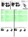
Abmessungen
Technische Daten Technical data
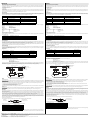
Elektrischer Anschluss
Kurven/
Zusätzliche Informationen
Electrical connection
Curves/additional information
Dimensions
UDC-18GMA-400-3E3-
Auswerteeinheit mit
Empfangseinheit
Sendeeinheit
Litzen 70 mm mit
Aderendhülsen
ø6,3
30
20
M6
36
54
86
LEDs
18
87
10
4510
M18x1
l = 5 m
l = 70 mm
11
-
Evaluation unit with
receiver unit
Emitter unit
wires 70 mm with
wire end ferrules
ø6,3
30
20
M6
36
54
86
LEDs
18
87
10
4510
M18x1
l = 5 m
l = 70 mm
11
Allgemeine Daten
Erfassungsbereich 20 ... 60 mm , optimaler Abstand: 45 mm
Wandlerfrequenz 395 kHz
Anzeigen/Bedienelemente
LED grün Anzeige: Einzelbogen detektiert
LED gelb Anzeige: kein Bogen detektiert (Luft)
LED rot Anzeige: Doppelbogen detektiert
Elektrische Daten
Betriebsspannung UB18 ... 30 V DC , Welligkeit 10 %SS
Leerlaufstrom I0< 80 mA
Bereitschaftsverzug tv< 500 ms
Eingang
Eingangstyp Funktionseingang
0-Pegel: -UB ... -UB + 1V
1-Pegel: +UB - 1 V ... +UB
Impulsdauer ≥ 100 ms
Impedanz ≥ 4 kΩ
Ausgang
Ausgangstyp 3 Schaltausgänge PNP, Öffner
Bemessungsbetriebsstrom Ie3 x 100 mA , kurzschluss-/überlastfest
Spannungsfall Ud≤ 3 V
Einschaltverzug ton ca. 15 ms (kürzere Ansprechzeit auf Anfrage)
Ausschaltverzug toff ca. 15 ms (kürzere Ansprechzeit auf Anfrage)
Impulsverlängerung min. 120 ms parametrierbar
Umgebungsbedingungen
Umgebungstemperatur 0 ... 60 °C (32 ... 140 °F)
Lagertemperatur -40 ... 70 °C (-40 ... 158 °F)
Mechanische Daten
Anschlussart Kabel PVC , 5 m
Aderquerschnitt 0,14 mm2
Schutzart IP67
Material
Gehäuse Messing, vernickelt, Kunststoffteile PBT
Wandler Epoxidharz/Glashohlkugelgemisch; Schaum Polyurethan
Masse 300 g
Allgemeine Informationen
Ergänzende Informationen Schalterstellung des externen Programmieradapters:
"output load": pull-down
"output logic": inv
General specifications
Sensing range 20 ... 60 mm , optimal distance: 45 mm
Transducer frequency 395 kHz
Indicators/operating means
LED green indication: single sheet detected
LED yellow Indication: No sheet detected (Air)
LED red indication: double sheet detected
Electrical specifications
Operating voltage UB18 ... 30 V DC , ripple 10 %SS
No-load supply current I0< 80 mA
Time delay before availability tv< 500 ms
Input
Input type Function input
0-level: -UB ... -UB + 1V
1-level: +UB - 1 V ... +UB
Pulse length ≥ 100 ms
Impedance ≥ 4 kΩ
Output
Output type 3 switch outputs PNP, NC
Rated operating current Ie3 x 100 mA , short-circuit/overload protected
Voltage drop Ud≤ 3 V
Switch-on delay ton approx. 15 ms (shorter response time on request)
Switch-off delay toff approx. 15 ms (shorter response time on request)
Pulse extension min. 120 ms programmable
Ambient conditions
Ambient temperature 0 ... 60 °C (32 ... 140 °F)
Storage temperature -40 ... 70 °C (-40 ... 158 °F)
Mechanical specifications
Connection type cable PVC , 5 m
Core cross-section 0.14 mm2
Degree of protection IP67
Material
Housing nickel plated brass; plastic components: PBT
Transducer epoxy resin/hollow glass sphere mixture; polyurethane foam
Mass 300 g
General information
Supplementary information Switch settings of the external programming adapter:
"output load": pull-down
"output logic": inv
(BN)
(PK)
(WH)
(BK)
(GY)
+UB
-UB
(BU)
U
Normsymbol/Anschluss:
Doppelbogen-Kontrolle
Ausgang Doppelbogen
Ausgang Luft
Funktionseingang
Ausgang Einzelbogen
Empfohlende Abstände
Montage/Ausrichtung:
b
a
a = 5 ... 15 mm
b≥ 10 mm
β = 35˚
Montage/Ausrichtung:
(für sehr dicke Papiere)
a
β
b
Mounting/Adjustment
β = 35˚
(for very thick Papers)
a
β
b
Mounting/Adjustment
Recommended distances
b
a
a = 5 ... 15 mm
b≥ 10 mm
(BN)
(PK)
(WH)
(BK)
(GY)
+UB
-UB
(BU)
U
Standard symbol/Connection:
Double sheet control
Output double sheet
Output air
Output single sheet
Function input
Date 05/29/2019 DIN A3 -> DIN A7
Part. 70103909 45-5522
Doc.

Hinweise
Notes
Adressen / Addresses / Adresses / Direcciónes / Indirizzi
Contact Pepperl+Fuchs GmbH · 68301 Mannheim · Germany · Tel. +49 621 776-4411 · Fax +49 621 776-27-4411 · E-mail: fa-inf[email protected]epperl-fuchs.com
Worldwide Headquarters: Pepperl+Fuchs GmbH · Mannheim · Germany · E-mail: info@de.pepperl-fuchs.com
USA Headquarters: Pepperl+Fuchs Inc. · Twinsburg · USA · E-mail: fa-info@us.pepperl-fuchs.com
Asia Pacific Headquarters: Pepperl+Fuchs Pte Ltd · Singapore · E-mail: fa-inf[email protected]perl-fuchs.com · Company Registration No. 199003130E
For more contact-adresses refer to the catalogue or internet: http://www.pepperl-fuchs.com
Beschreibung der Sensorfunktionen
Die Ultraschall Doppelbogen-Kontrolle zur Doppelbogenerkennung wird überall dort eingesetzt, wo eine automatische Unterscheidung von Doppelbogen
und Einzelbogen notwendig ist, um Maschinen zu schützen oder Ausschuss zu vermeiden. Die Doppelbogen-Kontrolle basiert auf dem Ultraschall-Einweg-
Prinzip. Es lassen sich detektieren:
- kein Bogen, d.h. Luft,
- Einzelbogen
- Doppelbogen
Die Auswertung der Signale erfolgt mit einem Mikroprozessorsystem. Als Folge derAuswertung werden die entsprechenden Schaltausgänge gesetzt. Sich
ändernde Umgebungsbedingungen wie Temperatur oder Feuchtigkeit werden automatisch kompensiert. Die Auswerteelektronik ist in einer Auswerteein-
heit zusammen mit einem Sensorkopf in einem kompakten M18 Metallgehäuse eingebaut.
Anschaltung
Der Sensor verfügt über 6 Anschlüsse. Die Funktion der Anschlüsse sind in der Nachfolgenden Tabelle aufgeführt. Der Funktionseingang (PK) dient zur
Parametrierung des Sensors. (siehe Ausgangsimpulsverlängerung, Ausrichthilfe und Programmauswahl). Im laufenden Betrieb muss der Funktionsein-
gang immer fest mit +UB oder -UB verbunden sein, um eventuelle Störungen oder Fehlfunktionen zu vermeiden.
Normalbetrieb
Der Sensor arbeitet im Normalbetrieb, wenn der Funktionseingang (PK) bei Anlegen der Versorgungsspannung (Power-On) auf -UB oder +UB gelegt ist,
entsprechend Tabelle Ausgangsimpulsverlängerung (siehe unten).
Anzeigen:
LED gelb: Erkennung Luft
LED grün: Erkennung Einzelbogen
LED rot: Erkennung Doppelbogen
Schaltausgänge:
Nur im Normalbetrieb sind die Schaltausgänge aktiv!
Weiß: WH Ausgang Einzelbogen
Schwarz: BK Ausgang Doppelbogen
Grau: GY Ausgang Luft
Ausgangsimpulsverlängerung
Durch Anschalten des Funktionseingangs (PK) an -UB oder +UB kann eine Mindestimpulsbreite von 120 ms für alle Ausgangsimpulse der drei Schaltaus-
gänge gewählt werden.
Achtung:
Es kann dadurch zu einem Zustand kommen, bei dem mehr als nur ein Schaltausgang durchgeschaltet ist!
Anzeigemodus
Die voreingestellte Parametrierung des Sensors kann angezeigt werden, indem man während des Normalbetriebs den Funktionseingang (PK) spannungs-
frei schaltet. Die grüne LED zeigt die Programmnummer an (Anzahl der Blinkimpulse (1..4) = Programmnummer).
Die Ausgänge sind in dieser Zeit inaktiv.Falls beim Anlegen der Versorgungsspannung (Power-On) der Funktionseingang (PK) spannungsfrei geschaltet
ist so arbeitet der Sensor ebenfalls im Anzeigebetrieb. Falls während des Betriebs der Funktionseingang (PK) durch einen Fehler (Kabelbruch, Lösen durch
Vibrationen) spannungsfrei geschaltet ist, so dient der Anzeigemodus als Störanzeige.
Parametrierung
Der Sensor verfügt über 4 Programme für verschiedene Einsatzbereiche. Dies ermöglicht die Erfassung eines breiten Materialspektrums. Der Anwender
kann das für seine Applikation geeignete Programm auswählen. Die Standardeinstellung Programm 1 ist so gewählt, dass für die Mehrheit der Applikatio-
nen keine Änderung der Einstellung notwendig ist.
Programme
*) Die Messungen wurden bei folgenden Bedingungen aufgenommen: d = 45 mm, a = 10 mm,
β
= 0°
**) Die Messungen wurden bei folgenden Bedingungen aufgenommen: d = 45 mm, a = 10 mm,
β
= 35°
Vorgehensweise bei der Parametrierung
Aus dem Anzeigemodus heraus kann zyklisch in weitere Parametriermodi gewechselt werden:
Modus Ausrichthilfe -->
Modus Programmauswahl -->
Modus Ausrichthilfe --> (zur Kontrolle)
Durch Legen des Funktionseingangs (PK) auf -UB (für > 500 ms) erfolgt der Moduswechsel. Innerhalb des Modus „Programmauswahl“ wird durch Anschal-
ten des Funktionseingangs (PK) an +UB (für > 500 ms) die nächste Programmstufe gewählt. Durch Abtrennen der Versorgungsspannung verlassen sie den
aktuellen Modus mit der gewählten Programmänderung.Die Schaltausgänge sind während der Parametrierung des Sensors nicht aktiv!
Modi
Amplitudenkontrolle
Bei der Montage kann die Amplitudenkontrolle zur Überprüfung auf ausreichende Ultraschallamplitude am Empfänger verwendet werden. Ist der Sender
zum Empfänger nicht optimal ausgerichtet, so kommt nicht die volle Schallenergie am Empfänger an. Dies kann dazu führen, dass Materialien nicht korrekt
detektiert werden können.
Wenn der Sensor den Luftbereich erkennt (gelbe LED leuchtet), dann beginnt die UDC die Stärke des gemessenen Amplitudensignals anzuzeigen:
- bei einem schwachen Signal blinkt die gelbe LED mit niedriger Frequenz
- mit steigender Signalstärke steigt die Blinkfrequenz
- bei ausreichender Signalstärke leuchtet die gelbe LED permanent.
Die Funktion Einzelbogen (grüne LED) und Doppelbogen (rote LED) ist hierbei weiterhin aktiv. Es kann somit die korrekte Funktion des Sensors überprüft
werden.
Programmwahl
Im Modus Programmwahl wird durch die grüne LED die aktuelle Programmnummer angezeigt (Anzahl der Blinkimpulse = Programmnummer). Durch Le-
gen des Einstelleingangs (PK) auf +UB (für > 500 ms) wird zyklisch das nächste Programm gewählt (Programm 1 schliesst an Programm 4 an).
Hinweise:
Ein komplettes Gerät besteht aus einem Ultraschall-Sender und einem Auswertegerät mit Ultraschall-Empfänger. Die Sensorköpfe sind ab Werk optimal
aufeinander abgestimmt und dürfen daher nicht getrennt verwendet werden. Die Stecker-Trennstelle am Verbindungskabel Sender-Empfänger dient ledig-
lich der leichteren Montage.
Sehr luftige Papiere (z.B. Taschentücher) oder Papiere mit Löchern sind aus physikalischen Gründen nicht immer zur Doppelbogenerkennung geeignet.
Werden mehrere Doppelbogenkontrollen in unmittelbarer Nähe eingesetzt, kann es zur gegenseitigen Beeinflussung und damit zur Fehlfunktion der Geräte
kommen. Gegenseitige Beeinflussung ist durch geeignete Gegenmaßnahmen bereits bei der Planung der Anlagen zu vermeiden.
Es ist bei der Installation darauf zu achten, dass das Ultraschallsignal das zu erfassende Material nicht durch Mehrfachreflexionen umgehen kann. Dies
kann geschehen, wenn z. B. größere Flächen zur Schallreflexion quer zur Ausbreitungsrichtung des Schalls zur Verfügung stehen. Dies kann durch unge-
eignete Haltevorrichtungen oder durch großflächige Anlagenteile der Fall sein. Im Falle reflektierender Anlagenteile, müssen diese entweder mit Schall ab-
sorbierendem Material beklebt werden oder ein anderer Montageort gewählt werden.
Parametrierung mit PACTware DTM
Der Anschluss des Doppelbogensensors erfolgt z.B. über den Klemmenadapter V15S-G-0,3M-PUR-WAGO.
Verbinden Sie den Sensor mit dem Klemmenadapter gemäß nachfolgender Tabelle.
Der Sensor ist mit einem Zeitschloss versehen. Falls kein Kommunikationsaufruf erfolgt, sperrt dies den Sensor 30 Sekunden nach dem Zuschalten der
Versorgungsspannung gegen Parametrieren. Starten Sie PACTware schon bevor Sie den Sensor einschalten damit der Kommunikationsaufruf rechtzeitig
erfolgen kann.
Farbe Anschaltung Bemerkung
BN +UB
WH Schaltausgang Einzelbogen Impulsbreite entsprechend dem Ereignis
BK Schaltausgang Doppelbogen Impulsbreite entsprechend dem Ereignis
GY Schaltausgang Luft Impulsbreite entsprechend dem Ereignis
PK -UB/+UBFunktionseingang zur Parametrierung/Impulsverlängerung
BU -UB
Anschaltung (PK) Schaltverhalten (nach Power-On)
-UBKeine Ausgangsimpulsverlängerung der Schaltausgänge
+UBAusgangsimpulsverlängerung aller Schaltausgänge auf mindestens 120 ms
Programmnummer Anmerkungen* Materialspektrum
1Standardeinstellung Standardpapiere 20 - 1200 g/m2
2Dicke Papiere, Kartonagen, feine Wellpappen (DIN 55 468-1) und
dünne Bleche** > 100 g/m2
3Dünne Papiere 20 – 250 g/m2
4Feinstpapiere < 40 g/m2
Aderfarbe Klemmenadapter Aderfarbe Sensorkabel
braun braun
blau blau
schwarz schwarz
grau pink
Power ON Normalbetrieb
Anzeigemodus
Umschaltung
Impulsverlängerung
... und Funktionseingang
(PK) spannungsfrei
Funktionseingang
(PK) spannungsfrei
... und Funktionseingang (PK)
auf +UB oder -UB legen
keine Funktion wähle zyklisch
nächstes Programm
Anzeigemodus
Ausrichthilfe
(gelbe LED)
Programmwahl
(grüne LED)
+UB
-UB
-UB
-UB
+UB+UB
M12 Buchse
des UC-PROG1
Anschlusskabel des
Doppelbogensensors
V15S-G-0,3M-PUR-WAGO
Description of sensor functions
The ultrasonic double sheet monitor is used for double sheet detection in all situations in which the automatic distinction between double and single sheets
is required in order to protect machines or avoid waste production. The double-sheet monitor is based on the ultrasonic through-beam principle. The follo-
wing can be detected:
- No sheet, i.e. air,
- Individual sheet
- Double sheet
A microprocessor system evaluates the signals. The appropriate switch outputs are set as a result of the evaluation. Changes in ambient conditions such as
temperature and humidity are compensated for automatically. The interface electronics is integrated into a compact M18 metal housing together with a sen-
sor head.
Switching on
The sensor is equipped with 6 connections. The functionality of the connections is described in the following table. The function input (PK) is used to assign
parameters to the sensor. (See Output pulse extension, Alignment aid and Program selection). During normal operation, the function input must always be
securely connected with +UB or -UB, to avoid possible interference or improper functionality.
Normal mode
The sensor is working in normal mode if the function input (PK) is applied to -UB or +UB when the power source (Power-On) is supplied, as shown in the
output pulse extension table (see below).
Displays:
LED yellow: Detection of air
LED green: Detection of single sheets
LED red: Detection of double sheets
Switch outputs:
The switch outputs are only active in normal operation!
White: WH Single sheet output
Black: BK Double sheet output
Gray: GY Air output
Output pulse extension
Switching the function input (PK) on to -UB or +UB makes it possible to select a minimum pulse width of 120 ms for all output pulses of the three switch out-
puts.
Please note:
This can result in a condition in which more than one switch output is switched through!
Display Mode
The selected parameter assignment of the sensor can be displayed by switching the function input (PK) to voltage-free during normal operation. The green
LED displays the program number (the number of flashing pulses (1 ... 4) = the program number).
The outputs are inactive during this time.If the function input (PK) is switched to voltage-free when power is supplied (Power-On), the sensor will also work
in display mode. If the unit is switched to voltage-free while the function input (PK) is in operation due to an error (broken cable, coming loose because of
vibration), display mode acts as a fault display.
Parameter assignment
The sensor is equipped with 4 programs for different ranges of application. This makes it possible to work with a wide range of material. The user can select
the program best suited for a specific application.The default setting, Program 1, is designed so that no change in the setting is required for most applications.
Programs
*) The measurements were made under the following conditions: d = 45 mm, a = 10 mm,
β
= 0°
*) The measurements were made under the following conditions: d = 45 mm, a = 10 mm,
β
= 35°
Procedure for assigning parameters
It is possible to switch to additional parameter assignment modes from the display mode:
Alignment mode -->
Program selection mode -->
Alignment aid mode --> (for checking)
When the function input (PK) is applied to -UB (for > 500 ms), the mode changes. When the "Program selection“ mode is active, switching on function input
(PK) on to +UB (for > 500 ms) selects the next program level. Disconnecting the power supply causes the system to exit the current mode with the selected
program change. The switch outputs are not active while parameters are being assigned to the sensor!
Modes
Amplitude control
During installation, the amplitude control can be used to check whether the ultrasonic amplitude at the receiver is sufficient. If the transmitter is not aligned
properly in relation to the receiver, maximum sound energy is not transmitted to the receiver, which may result in the incorrect detection of materials.
When the sensor detects an area of air (yellow LED lights up), the UDC begins to display the strength of the measured amplitude signal:
- if the signal is weak, the yellow LED flashes at low frequency
- the flashing frequency increases in line with the signal strength
- the yellow LED lights up continuously when the signal strength is sufficient.
The single sheet function (green LED) and double sheet function (red LED) are now active. This can be used to check the correct function of the sensor.
Program selection
In the program selection mode, the current program is displayed by the green LED (number of flashing pulses = program number). Applying the adjustment
input (PK) to +UB (for > 500 ms) causes the next program to be selected in cyclic sequence (program 1 follows through to program 4).
Notes:
A complete device consists of an ultrasonic emitter and an evaluation unit with an ultrasonic emitter. The sensor heads are optimally adjusted to each other
when they leave the factory. Therefore, they must not be used separately or exchanged with other devices of the same type. The plug connector on the
emitter/receiver connection cable is only intended to be used for easier mounting, not to replace units.
Very light papers (for example handkerchiefs) or perforated papers are not always suitable for double sheet detection because of their physical characteris-
tics.
If two or more double sheet controls are used in the immediate vicinity of each other, there may be mutual interference between them, which can result
in improper functionality of the devices. Mutual interference can be prevented by introducing suitable countermeasures when planning systems.
When installing, care has to be taken that the ultrasonic signal cannot pass around the material that is to be detected, due to multiple reflections. This can
happen if large surfaces are present at right angles to the direction of sound propagation. This can be the case if unsuitable mounting brackets are used, or
if assemblies with large surface are part of the machine. In the latter case such machine parts should be covered by sound absorbing material or a different
location for the installation should be chosen.
Parameterization using PACTware DTM
The double sheet sensor can be connected using a V15S-G-0.3M-PUR-WAGO terminal adapter.
Connect the sensor to the terminal adapter according to the table below.
The sensor features a time lock. If no communication request occurs, the time lock blocks parameterization of the sensor 30 seconds after the supply voltage
is connected. Start PACTware before switching on the sensor so that the communication request can be made in time.
Colour Switching on Comments
BN +UB
WH Switch output for single sheets Pulse width corresponds to the event
BK Switch output for double sheets Pulse width corresponds to the event
GY Switch output for air Pulse width corresponds to the event
PK -UB/+UBFunction input for parameter assignment/pulse prolongation
BU -UB
Switching on (PK) Operating behaviour (after Power-On)
-UBNo output pulse extension for switch outputs
+UBOutput pulse extension of all switch outputs to at least 120 ms
Program number Notes: Range of materials
1Default setting, standard paper 20 - 1200 g/m2
2Thick paper, cardboard, fine corrugated boards(DIN 55 468--1)and
thin sheet metal** > 100 g/m2
3Thin paper 20 – 250 g/m2
4Extremely fine paper < 40 g/m2
Terminal adapter wire color Sensor cable wire color
Brown Brown
Blue Blue
Black Black
Gray Pink
Power ON Normal mode
Indication mode
activate/deactivate
output pulse
prolongation
... and function input
(PK) unconnected
Function input
(PK) unconnected
... and function input (PK)
connected to +UB or -UB
no function toggle cyclically
next program
Indication mode
Alignment aid
(yellow LED)
Program select
(green LED)
+UB
-UB
-UB
-UB
+UB+UB
M12 socket for
the UC-PROG1
Connection cable for
the double sheet sensor
V15S-G-0.3M-PUR-WAGO
-
 1
1
-
 2
2


Pepperl+Fuchs UDC-18GMA-400-3E3-Y70103909 Bedienungsanleitung
- Typ
- Bedienungsanleitung
in anderen Sprachen
Verwandte Artikel
-
Pepperl+Fuchs UDC-18GMA-400-3E3 Bedienungsanleitung
-
-
-
-
-
-
-
-
-