
Operating instructions
Betriebsanleitung
Mode d'emploi
Manual de instrucciones
EN
DE
FR
ES
OEM-Druckschalter mit Anzeige, Typ PSD-4-ECO
OEM pressure switch with display, model PSD-4-ECO
OEM pressure switch with display, model PSD-4-ECO
Pressostat OEM avec afficheur, type PSD-4-ECO
Presostato con display OEM, modelo PSD-4-ECO

2 WIKA operating instructions, model PSD-4-ECO
EN
DE
FR
ES
14247391.01 07/2019 EN/DE/FR/ES
© 07/2019 WIKA Alexander Wiegand SE & Co. KG
All rights reserved. / Alle Rechte vorbehalten.
WIKA® is a registered trademark in various countries.
WIKA® ist eine geschützte Marke in verschiedenen Ländern.
Prior to starting any work, read the operating instructions!
Keep for later use!
Vor Beginn aller Arbeiten Betriebsanleitung lesen!
Zum späteren Gebrauch aufbewahren!
Lire le mode d‘emploi avant de commencer toute opération !
A conserver pour une utilisation ultérieure !
¡Leer el manual de instrucciones antes de comenzar cualquier trabajo!
¡Guardar el manual para una eventual consulta!
Betriebsanleitung Typ PSD-4-ECO Seite 37 - 70
Operating instructions model PSD-4-ECO Page 3 - 36
Mode d‘emploi type PSD-4-ECO Page 71 - 104
Manual de instrucciones modelo PSD-4-ECO Página 105 - 139

14247391.01 07/2019 EN/DE/FR/ES
3WIKA operating instructions, model PSD-4-ECO
EN
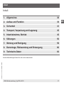
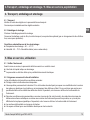
Contents
Declarations of conformity can be found online at www.wika.com
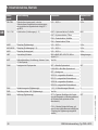
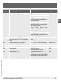
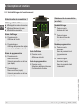
Contents
1. General information 4
2. Design and function 5
3. Safety 7
4. Transport, packaging and storage 11
5. Commissioning, operation 11
6. Faults 22
7. Maintenance and cleaning 25
8. Dismounting, return and disposal 26
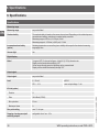
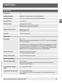
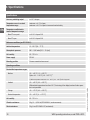
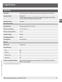
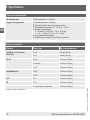
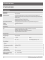
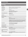
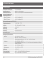
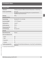
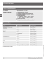
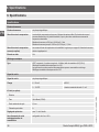
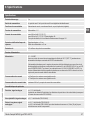
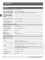
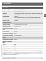
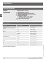
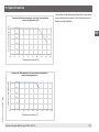
9. Specications 28

14247391.01 07/2019 EN/DE/FR/ES
4 WIKA operating instructions, model PSD-4-ECO
EN
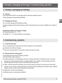
1. General information
1. General information
■
The instrument described in the operating instructions has been designed and manufactured using state-of-the-
art technology. All components are subject to stringent quality and environmental criteria during production. Our
management systems are certied to ISO 9001 and ISO 14001.
■
These operating instructions contain important information on handling the instrument. Working safely requires that
all safety instructions and work instructions are observed.
■
Observe the relevant local accident prevention regulations and general safety regulations for the instrument’s range
of use.
■
The operating instructions are part of the product and must be kept in the immediate vicinity of the instrument and
readily accessible to skilled personnel at any time. Pass the operating instructions on to the next operator or owner
of the instrument.
■
Skilled personnel must have carefully read and understood the operating instructions prior to beginning any work.
■
The general terms and conditions contained in the sales documentation shall apply.
■
Subject to technical modications.
■
Further information:
- Internet address: www.wika.de / www.wika.com
- Relevant data sheet: PE 81.69
- Application consultant: Tel.: +49 9372 132-0
Fax: +49 9372 132-406

14247391.01 07/2019 EN/DE/FR/ES
5WIKA operating instructions, model PSD-4-ECO
EN
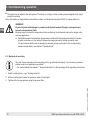
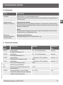
2. Design and function
2. Design and function
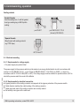
2.1 Scope of delivery
■
Pressure switch
■
Operating instructions
Cross-check scope of delivery with delivery note.
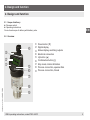
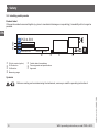
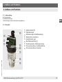
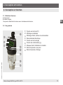
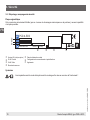
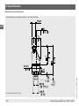
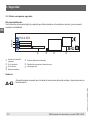
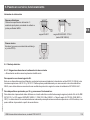
2.2 Overview
Down button [▼]
Digital display
Status display, switching outputs
Electrical connection
Up button [▲]
Confirmation button [◊]
Stop mark, rotation limitation
Process connection, spanner flats
Process connection, thread

14247391.01 07/2019 EN/DE/FR/ES
6 WIKA operating instructions, model PSD-4-ECO
EN
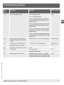
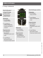
4-digit LED display
■
Display of pressure value
■
Display of menu item
■
Display of parameter
Status of switching output 1
Display mode
▶
Short press
Display of unit
▶
Long press
Jumping into the programming
mode
Programming mode
▶
Short press
Menu up
Parameter value up (step-wise)
▶
Long press
Menu up (fast)
Parameter value up (fast)
Display mode
▶
Short press
Display of unit
▶
Long press
Display of the set parameters,
see chapter 5.7 “Parameters”
Programming mode
▶
Short press
Menu down
Parameter value down
(step-wise)
▶
Long press
Menu down (fast)
Parameter value down (fast)
Display mode
▶
Short press
Display of unit
Programming mode
▶
Short press
Selection of menu item
Conrmation of input
2.3 Display and operating unit
2. Design and function
Status of switching output 2
(optional)

14247391.01 07/2019 EN/DE/FR/ES
7WIKA operating instructions, model PSD-4-ECO
EN
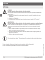
3. Safety
3. Safety
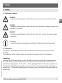
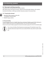
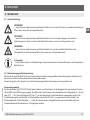
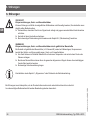
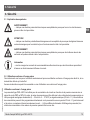
3.1 Explanation of symbols
WARNING!
... indicates a potentially dangerous situation that can result in serious injury or death, if not avoided.
CAUTION!
... indicates a potentially dangerous situation that can result in light injuries or damage to property or the
environment, if not avoided.
WARNING!
... indicates a potentially dangerous situation that can result in burns, caused by hot surfaces or liquids,
if not avoided.
Information
... points out useful tips, recommendations and information for ecient and trouble-free operation.
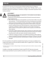
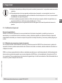
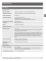
3.2 Intended use
The instrument has been designed and built solely for the intended use described here, and may only be used
accordingly.
The manufacturer shall not be liable for claims of any type based on operation contrary to the intended use.
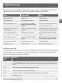
Intended use
The model PSD-4-ECO pressure switch is used for the switching of circuits as a function of the measured pressure
via a PNP or NPN output signal. In addition, the pressure value can be output to appropriate read-out units as a
standardised analogue signal (4 ... 20 mA or DC 0 ... 10 V) or digital signal (IO-Link 1.1). The switching conditions can
be programmed directly at the pressure switch or by means of IO-Link 1.1 (switch and reset points, normally closed/
normally open, ...). Via the dierent display elements of the pressure switch, switching states and pressure values can
be read on site.

14247391.01 07/2019 EN/DE/FR/ES
8 WIKA operating instructions, model PSD-4-ECO
EN
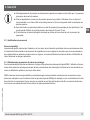
3. Safety
The model PSD-4-ECO has been developed for the pressure measurement of non-hazardous uids, liquids and gases
(classication in accordance with Directive 2014/68/EU Article 13, Regulation (EC) No. 1272/2008, or GHS
1)
) which
are mainly used for cooling, lubrication, cleaning or power transmission in industrial machines.
WARNING!
Physical injuries and damage to property and the environment through exceeding the perfor-
mance limits
Exceeding the performance limits can destroy the instrument and lead to danger in the end-use
application.
▶
Only use the instrument in applications that lie within its technical performance limits. → For
performance limits, such as derating (maximum current consumption at a corresponding medium
temperature), see chapter 9 “Specifications”
▶
Any permanent operation in the overload range is not permitted. Above the highest operating
pressure permitted, up to the overload limit, the pressure sensor is operating outside its specifica-
tion. The overload range is intended to prevent damage to the pressure sensor, as part of a pressure
vessel system, during the pressure containment test.
▶
The overload limit must never be exceeded, even when failures occur in the end-use application.
Loads above the overload limit can cause irreversible damage, which can lead, for example, to
permanent measuring errors.
▶
The manufacturer or operator of the machine or plant in which the product is used must ensure the
compatibility of the materials of the wetted parts with the medium used.
▶
The pressure switch should not be used with abrasive or unstable fluids, in particular not with
hydrogen.
Special versions for oil and grease-free applications, as well as for use with oxygen (dangerous uid according to
Directive 2014/68/EU Article 13, Regulation (EC) No. 1272/2008, or GHS
1)
), are available on request.
1) Globally Harmonized System of Classication, Labelling and Packaging of Chemicals
The (dis-)mounting, installation, parameterisation and maintenance of the model PSD-4 ECO in industrial
environments absolutely requires suitably skilled personnel in accordance with chapter 3.3. “Personnel qualication”.

14247391.01 07/2019 EN/DE/FR/ES
9WIKA operating instructions, model PSD-4-ECO
EN
■
Pressure surges below the nominal pressure and shorter than 1 ms can cause measuring errors.
■
For applications where pressure spikes can occur, the use of a restrictor is recommended. The
restrictor narrows the pressure port to 0.6 mm and thus increases the resistance against pressure
spikes.
■
With media that could block the pressure port (e.g. through particles), it is recommended to use a
wider pressure port of 6 or 12 mm.
■
There must be no build-up of atomic hydrogen in the pressure port of the pressure switch.
3.3 Personnelqualication
Skilled personnel
Skilled personnel, authorised by the operator, are understood to be personnel who, based on their technical training,
knowledge of measurement and control technology and on their experience and knowledge of country-specic regula-
tions, current standards and directives, are capable of carrying out the work described and independently recognising
potential hazards.
3.4 Use of accessories and spare parts
It is recommended to use original accessories and original spare parts from WIKA. Using accessories and spare parts
from third parties can lead to damage to the instrument or accidents, due to quality defects or other reasons.
WIKA assumes no liability for damage or accidents caused by a malfunction or unsuitability of accessories and spare
parts which do not originate from WIKA (e.g. non-compliance with the IP ingress protection of connectors). No warranty
claims can be made which arise due to a malfunction or unsuitability of any accessory or spare part from a third party.
3. Safety

14247391.01 07/2019 EN/DE/FR/ES
10 WIKA operating instructions, model PSD-4-ECO
EN
3. Safety
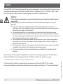
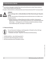
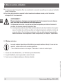
3.5 Labelling, safety marks
Product label
If the serial number becomes illegible (e.g. due to mechanical damage or overpainting), traceability will no longer be
possible.
IO-Link version (option)
Coded date of manufacture
P# Product no.
Pin assignment and specications
S# Serial no.
Approvals
Measuring range
Symbols
Before mounting and commissioning the instrument, ensure you read the operating instructions!
PSD-4-ECO
www.wika.com Made in Germany

14247391.01 07/2019 EN/DE/FR/ES
11WIKA operating instructions, model PSD-4-ECO
EN
4. Transport, packaging and storage / 5. Commissioning, operation
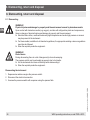
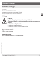
4. Transport, packaging and storage
4.1 Transport
Check the pressure switch for any damage that may have been caused by transport.
Obvious damage must be reported immediately.
4.2 Packaging and storage
Do not remove packaging until just before mounting.
Keep the packaging as it will provide optimum protection during transport (e.g. change in installation site, sending for
repair).
Permissible conditions at the place of storage:
■
Storage temperature: -40 ... +70 °C
■
Humidity: 45 ... 75 % relative humidity (no condensation)
5. Commissioning, operation
5.1 Check the instrument
Prior to commissioning, the pressure switch must be subjected to a visual inspection.
■
Leaking uid is indicative of damage.
■
Only use the pressure switch if it is in perfect condition with respect to safety.
5.2 Requirements for mounting point
The mounting point must meet the following conditions:
■
Protected from weather inuences.
■
Permanent exposure to UV light/sunlight can lead to a change in the colour of the plastic parts and a clouding/
yellowing of the status displays. Therefore, a possible limitation of the visibility of the status displays cannot be
excluded. However, this has no eect on the functionality of the instrument.
■
Under corrosive environmental conditions (such as salty, humid air), reductions in the gloss level of the metallic
surfaces, or even corrosion on the instrument, may occur, which make readability of the product label more dicult.
However, this has no eect on the functionality of the instrument.
■
Sealing faces are clean and undamaged.
■
Sucient space for a safe electrical installation.

14247391.01 07/2019 EN/DE/FR/ES
12 WIKA operating instructions, model PSD-4-ECO
EN
5. Commissioning, operation
■
The instrument is vented to the atmosphere. Therefore, no coating or other covering may be applied which might
restrict the venting.
■
For information on tapped holes and welding sockets, see Technical information IN 00.14 at www.wika.com.
WARNING!
Physical injuries and damage to property and the environment through running above or
below the temperature limits
Running above or below the temperature limits can destroy the instrument and lead to danger in the
end-use application.
▶
Permissible ambient and medium temperatures remain within the performance limits. Consider
possible restrictions on the ambient temperature range caused by mating connector used.
For performance limits, such as derating (maximum current consumption at a corresponding
medium temperature), see chapter 9 “Specifications”
5.3 Mechanical mounting
The max. torque depends on the mounting point (e.g. material and shape). If you have any questions,
please contact our application consultant.
→ For contact details see chapter 1 “General information” or the back page of the operating instructions.
1. Seal the sealing face (→ see “Sealing variants”).
2
.
At the mounting point, screw the pressure switch in hand-tight.
3
.
Tighten with a torque spanner using the spanner ats.

14247391.01 07/2019 EN/DE/FR/ES
13WIKA operating instructions, model PSD-4-ECO
EN
5. Commissioning, operation
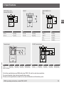
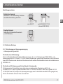
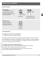
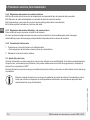
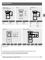
Sealing variants
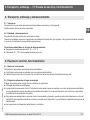
5.4 Electrical mounting
5.4.1 Requirements for voltage supply
→ For power supply see product label
The power supply for the pressure switch must be made via an energy-limited electric circuit in accordance with
section 9.4 of UL/EN/IEC 61010-1, or an LPS per UL/EN/IEC 60950-1 / CSA C22.2 no. 60950-1, or class 2 in
accordance with UL1310/UL1585 (NEC or CEC). The voltage supply must be suitable for operation above 2,000 m
should the pressure switch be used at this altitude.
5.4.2 Requirements for electrical connection
■
Ingress protection of the mating connector corresponds to the ingress protection of the pressure switch.
■
Cable diameter matches the cable bushing of the mating connector.
■
Cable gland and seals of the mating connector are correctly seated.
■
No humidity can ingress at the cable end.
Parallel threads
Seal the sealing face with flat gasket,
lens-type sealing ring or WIKA profile
sealing.
per EN 837
per DIN EN ISO 1179-2
(formerly DIN 3852-E)
Tapered threads
Wrap threads with sealing material
(e.g. PTFE tape).
NPT, R and PT

14247391.01 07/2019 EN/DE/FR/ES
14 WIKA operating instructions, model PSD-4-ECO
EN
5. Commissioning, operation
5.4.3 Requirement for shielding and grounding
The pressure switch must be grounded via the process connection.
When working during a running process operation, measures to prevent electrostatic discharge on the connection
terminals should be taken, as a discharge could lead to temporary corruption of the measured value.
5.4.4 Connecting the instrument
1. Assemble the mating connector or cable outlet.
→Pin assignment, see product label
2
.
Establish the plug connection.
5.5 Zero point setting
Check the indicated zero point on the digital display during commissioning. Should a zero point oset be displayed as
a result of installation, this can be reset in programming mode or via IO-Link with the 0SET parameter
Only carry out zero point setting for gauge and vacuum pressure measuring ranges at the start of the measuring range.
Carry out zero point setting of absolute pressure measuring ranges at 0 bar absolute (vacuum). Since
appropriate references are required for this, we recommend that this is only carried out by the manufac-
turer.

14247391.01 07/2019 EN/DE/FR/ES
15WIKA operating instructions, model PSD-4-ECO
EN
5. Commissioning, operation
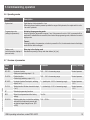
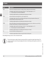
5.6 Operating modes
Mode Description
System start Digital display is fully activated for 1 sec.
When the pressure switch is powered up within the range of the hysteresis, the output switch is set to
“not active” by default.
Programming mode
(setting the parameters)
Activating the programming mode
Keep the up button [▲] pressed for approx. 5 sec. If the password is set to ≠ 0000, a password will be
requested. If authentication is successful, then it enters the programming mode, otherwise it reverts to
display mode.
Timeout
If, during the setting of a parameter, no button is pressed for 60 s, the instrument returns to the display
mode with the value unchanged.
Display mode
(normal operation, display of
pressure value)
Returning to the display mode
Simultaneous pressing of the up and down buttons [▼] + [▲]
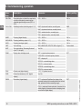
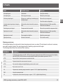
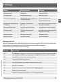
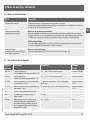
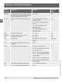
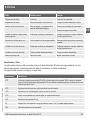
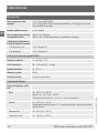
5.7 Overview of parameters
Menu
item
Description Parameter Factory setting
SP1/SP2 Hysteresis function:
Switch point (switching output 1 / 2)
0.25 ... 100 % of measuring range Nominal pressure
FH1/FH2 Window function:
Window high (switching output 1 / 2)
0.25 ... 100 % of measuring range Nominal pressure
RP1/RP2 Hysteresis function: Reset point, switching
output (1 or 2)
0 ... (switch point - 0.25 % of measuring range)
Nominal pressure
- 10 %
FL1/FL2 Window function: Window low switch output
(1 or 2)
0 ... (window high - 0.25 % of measuring range)
Nominal pressure
- 10 %
EF Extended programming functions
RES Return the set parameters to the factory
settings
Yes / No
DS1/DS2 Switching delay time, in which the switching
value must be continuously present until
an electrical signal change occurs (SP1
or SP2)
0.00 ... 65.00 s 0.00 s

14247391.01 07/2019 EN/DE/FR/ES
16 WIKA operating instructions, model PSD-4-ECO
EN
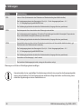
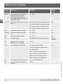
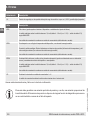
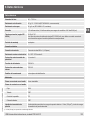
5. Commissioning, operation
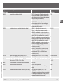
Menu
item
Description Parameter Factory setting
DR1/DR2 Reset delay time, at which the reset value
must be continuously present until an
electrical signal change occurs (RP1 or
RP2)
0.00 ... 65.00 s 0.00 s
OU1 / OU2 Switching function (switching output 1 / 2) HNO = hysteresis function, normally open HNO
HNC = hysteresis function, normally closed
FNO = window function, normally open
FNC = window function, normally closed
AVGD Damping (digital display) 0.00 ... 65.00 s 0.20 s
AVG1/AVG2 Damping (switching output 1 / 2) 0.00 ... 65.00 s 0.00 s
AVG3 Damping (analogue signal) 0.00 ... 65.00 s 0.00 s
UNIT Unit switching BAR, mBAR, MPA, KPA, PSI, KGcm (kg/cm²), % Order-related
0SET Zero point setting / Executing “Autozero”
(max. 3 % of span)
Yes / No
DISM Display value in display mode ACT = current system pressure ACT
LOW, HIGH = min/max system pressure
OFF = display o
SP1/FH1 = set switching value
RP1/FL1 = set reset value
SP2/FH2 = set switching value
RP2/FL2 = set reset value
DISU Refresh rate (digital display) 1, 2, 5, 10 updates/second 5
DISR Rotate the indication by 180° (digital
display)
Yes / No
DRES Resolution (digital display) OPT = optimised (Stabilises the display of the
measured values, with rounding factors for the last
digit, optimised for the measuring range)
FULL = maximum (nest resolution, if required, for a
stable display of measured values a damping must
be set for the digital display)
OPT

14247391.01 07/2019 EN/DE/FR/ES
17WIKA operating instructions, model PSD-4-ECO
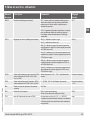
EN
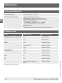
Menu
item
Description Parameter Factory setting
COLR Colour settings (digital display) rEd (0) = display always red rEd (0)
Grn (1) = display always green
rEd1 (2) = Red display, when the pressure value
is greater than/equal to the set value from CLRH
(otherwise green)
Grn1 (3) = Green display, when the pressure value
is greater than/equal to the set value from CLRH
(otherwise red)
rEd2 (4) = Red display, when the pressure value is
in the range of the set values of CLRL and CLRH
(otherwise green)
Grn2 (5) = Green display, when the pressure value
is in the range of the set values of CLRL and CLRH
(otherwise red)
CLRH Upper limit value of the COLR function
Only active if COLR = rEd1, rEd2, Grn1
or Grn2
Pressure value 0.25 ... 100 % of measuring range Nominal pressure
CLRL Lower limit value of the COLR function
Only active if COLR = Grn1 or Grn2
0 ... (CLRH - 0.25 % of measuring range) Nominal pressure
- 10 %
RHL Clear memory (min/max system pressure) Yes / No
PAS Password entry 0000 = no password
Password input digit by digit
0000
TAG Measuring instrument name (TAG) 32 selectable characters (A-Z ‚0 ... 9; - ‚SPACE)
(2 spaces in sequence terminate the input and lead
to the deletion of this and the underlying characters)
without
5. Commissioning, operation

14247391.01 07/2019 EN/DE/FR/ES
18 WIKA operating instructions, model PSD-4-ECO
EN
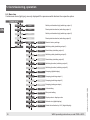
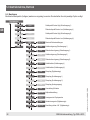
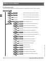
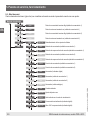
5.8 Menu tree
Certain menu items (light grey) are only displayed if the pressure switch features the respective option.
Display mode
SP1 / FH1 Value Switch point/window high (switching output 1)
RP1 / FL1 Value Reset point/window low (switching output 1)
SP2 / FH2 Value Switch point/window high (switching output 2)
RP2 / FL2 Value Reset point/window low (switching output 2)
EF RES Yes / No Reset to factory settings
END DS1 Value Switching delay (switching output 1)
DR1 Value Reset delay (switching output 1)
DS2 Value Switching delay (switching output 2)
DR2 Value Reset delay (switching output 2)
OU1 PARA Switching function (switching output 1)
OU2 PARA Switching function (switching output 2)
AVGD Value Damping (digital display)
AVG1 Value Damping (switching output 1)
AVG2 Value Damping (switching output 2)
AVG3 Value Damping (analogue output)
UNIT Unit Unit switching
0SET Yes / No Zero point setting
DISM PARA Display value in display mode
DISU Value Refresh rate (digital display)
DISR Yes / No Rotate the indication by 180° (digital display)
5. Commissioning, operation

14247391.01 07/2019 EN/DE/FR/ES
19WIKA operating instructions, model PSD-4-ECO
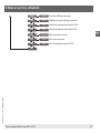
EN
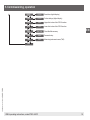
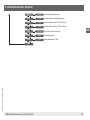
DRES PARA Resolution (digital display)
COLR PARA Colour settings (digital display)
CLRH Value Upper limit value of the COLR function
CLRL Value Lower limit value of the COLR function
RHL Yes / No Clear Min/Max memory
PAS Value Password entry
TAG Value Measuring instrument name (TAG)
END
5. Commissioning, operation

14247391.01 07/2019 EN/DE/FR/ES
20 WIKA operating instructions, model PSD-4-ECO
EN
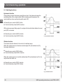
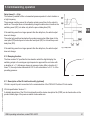
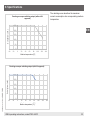
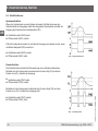
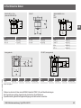
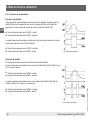
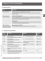
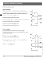
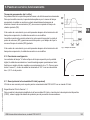
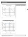
5.9 Switching functions
Hysteresis function
If the system pressure uctuates around the set point, the hysteresis keeps the
switching status of the outputs stable. With increasing system pressure, the
output switches when reaching the switch point (SP).
■
Normally open contact (HNO): Active
■
Contact normally closed (HNC): Inactive
With system pressure falling again, the output will not switch back before the reset
point (RP) is reached.
■
Normally open contact (HNO): Inactive
■
Contact normally closed (HNC): Active
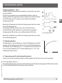
Window function
The window function allows for the control of a dened range.
When the system pressure is between window high (FH) and window low (FL),
the output switches on.
■
Normally open contact (FNO): Active
■
Contact normally closed (FNC): Inactive
When the system pressure is outside window high (FH) and window low (FL), the
output does not switch on.
■
Normally open contact (FNO): Inactive
■
Contact normally closed (FNC): Active
Fig.: Hysteresis function
Fig.: Window function
5. Commissioning, operation
Seite wird geladen ...
Seite wird geladen ...
Seite wird geladen ...
Seite wird geladen ...
Seite wird geladen ...
Seite wird geladen ...
Seite wird geladen ...
Seite wird geladen ...
Seite wird geladen ...
Seite wird geladen ...
Seite wird geladen ...
Seite wird geladen ...
Seite wird geladen ...
Seite wird geladen ...
Seite wird geladen ...
Seite wird geladen ...
Seite wird geladen ...
Seite wird geladen ...
Seite wird geladen ...
Seite wird geladen ...
Seite wird geladen ...
Seite wird geladen ...
Seite wird geladen ...
Seite wird geladen ...
Seite wird geladen ...
Seite wird geladen ...
Seite wird geladen ...
Seite wird geladen ...
Seite wird geladen ...
Seite wird geladen ...
Seite wird geladen ...
Seite wird geladen ...
Seite wird geladen ...
Seite wird geladen ...
Seite wird geladen ...
Seite wird geladen ...
Seite wird geladen ...
Seite wird geladen ...
Seite wird geladen ...
Seite wird geladen ...
Seite wird geladen ...
Seite wird geladen ...
Seite wird geladen ...
Seite wird geladen ...
Seite wird geladen ...
Seite wird geladen ...
Seite wird geladen ...
Seite wird geladen ...
Seite wird geladen ...
Seite wird geladen ...
Seite wird geladen ...
Seite wird geladen ...
Seite wird geladen ...
Seite wird geladen ...
Seite wird geladen ...
Seite wird geladen ...
Seite wird geladen ...
Seite wird geladen ...
Seite wird geladen ...
Seite wird geladen ...
Seite wird geladen ...
Seite wird geladen ...
Seite wird geladen ...
Seite wird geladen ...
Seite wird geladen ...
Seite wird geladen ...
Seite wird geladen ...
Seite wird geladen ...
Seite wird geladen ...
Seite wird geladen ...
Seite wird geladen ...
Seite wird geladen ...
Seite wird geladen ...
Seite wird geladen ...
Seite wird geladen ...
Seite wird geladen ...
Seite wird geladen ...
Seite wird geladen ...
Seite wird geladen ...
Seite wird geladen ...
Seite wird geladen ...
Seite wird geladen ...
Seite wird geladen ...
Seite wird geladen ...
Seite wird geladen ...
Seite wird geladen ...
Seite wird geladen ...
Seite wird geladen ...
Seite wird geladen ...
Seite wird geladen ...
Seite wird geladen ...
Seite wird geladen ...
Seite wird geladen ...
Seite wird geladen ...
Seite wird geladen ...
Seite wird geladen ...
Seite wird geladen ...
Seite wird geladen ...
Seite wird geladen ...
Seite wird geladen ...
Seite wird geladen ...
Seite wird geladen ...
Seite wird geladen ...
Seite wird geladen ...
Seite wird geladen ...
Seite wird geladen ...
Seite wird geladen ...
Seite wird geladen ...
Seite wird geladen ...
Seite wird geladen ...
Seite wird geladen ...
Seite wird geladen ...
Seite wird geladen ...
Seite wird geladen ...
Seite wird geladen ...
Seite wird geladen ...
Seite wird geladen ...
Seite wird geladen ...
Seite wird geladen ...
Seite wird geladen ...
-
 1
1
-
 2
2
-
 3
3
-
 4
4
-
 5
5
-
 6
6
-
 7
7
-
 8
8
-
 9
9
-
 10
10
-
 11
11
-
 12
12
-
 13
13
-
 14
14
-
 15
15
-
 16
16
-
 17
17
-
 18
18
-
 19
19
-
 20
20
-
 21
21
-
 22
22
-
 23
23
-
 24
24
-
 25
25
-
 26
26
-
 27
27
-
 28
28
-
 29
29
-
 30
30
-
 31
31
-
 32
32
-
 33
33
-
 34
34
-
 35
35
-
 36
36
-
 37
37
-
 38
38
-
 39
39
-
 40
40
-
 41
41
-
 42
42
-
 43
43
-
 44
44
-
 45
45
-
 46
46
-
 47
47
-
 48
48
-
 49
49
-
 50
50
-
 51
51
-
 52
52
-
 53
53
-
 54
54
-
 55
55
-
 56
56
-
 57
57
-
 58
58
-
 59
59
-
 60
60
-
 61
61
-
 62
62
-
 63
63
-
 64
64
-
 65
65
-
 66
66
-
 67
67
-
 68
68
-
 69
69
-
 70
70
-
 71
71
-
 72
72
-
 73
73
-
 74
74
-
 75
75
-
 76
76
-
 77
77
-
 78
78
-
 79
79
-
 80
80
-
 81
81
-
 82
82
-
 83
83
-
 84
84
-
 85
85
-
 86
86
-
 87
87
-
 88
88
-
 89
89
-
 90
90
-
 91
91
-
 92
92
-
 93
93
-
 94
94
-
 95
95
-
 96
96
-
 97
97
-
 98
98
-
 99
99
-
 100
100
-
 101
101
-
 102
102
-
 103
103
-
 104
104
-
 105
105
-
 106
106
-
 107
107
-
 108
108
-
 109
109
-
 110
110
-
 111
111
-
 112
112
-
 113
113
-
 114
114
-
 115
115
-
 116
116
-
 117
117
-
 118
118
-
 119
119
-
 120
120
-
 121
121
-
 122
122
-
 123
123
-
 124
124
-
 125
125
-
 126
126
-
 127
127
-
 128
128
-
 129
129
-
 130
130
-
 131
131
-
 132
132
-
 133
133
-
 134
134
-
 135
135
-
 136
136
-
 137
137
-
 138
138
-
 139
139
-
 140
140


in anderen Sprachen
- français: WIKA PSD-4-ECO Mode d'emploi
- español: WIKA PSD-4-ECO Instrucciones de operación
Verwandte Artikel
-
WIKA MH-3 tag:model:MH-3-HY Bedienungsanleitung
-
-
-
WIKA PSD-4-ECO Bedienungsanleitung
-
-
-
-
-
-
Andere Dokumente
-
IFM PN3056 Bedienungsanleitung
-
SICK PBS plus Pressure switch Bedienungsanleitung
-
-
AVENTICS Electron. Pressure Switch, Series PE2 Bedienungsanleitung
-
Baumer YTED Installationsanleitung
-
-
AVENTICS Pressure sensor PE5 Bedienungsanleitung
-
-
-
sauter XTP 2 Assembly Instructions