
Operating instructions
Betriebsanleitung
Mode d'emploi
Manual de instrucciones
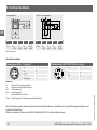
EN
DE
FR
ES
Drucksensor, Typ A-1200
Pressure sensor, model A-1200
Pressure sensor, model A-1200
Capteur de pression, type A-1200
Sensor de presión, modelo A-1200

2 WIKA operating instructions pressure sensor, model A-1200
EN
DE
FR
ES
14247390.02 11/2019 EN/DE/FR/ES
© 02/2019 WIKA Alexander Wiegand SE & Co. KG
All rights reserved. / Alle Rechte vorbehalten.
WIKA
®
is a registered trademark in various countries.
WIKA
®
ist eine geschützte Marke in verschiedenen Ländern.
Prior to starting any work, read the operating instructions!
Keep for later use!
Vor Beginn aller Arbeiten Betriebsanleitung lesen!
Zum späteren Gebrauch aufbewahren!
Lire le mode d‘emploi avant de commencer toute opération !
A conserver pour une utilisation ultérieure !
¡Leer el manual de instrucciones antes de comenzar cualquier trabajo!
¡Guardar el manual para una eventual consulta!
Betriebsanleitung, Typ A-1200 Seite 27 - 52
Operating instructions, model A-1200 Page 3 - 26
Mode d‘emploi, type A-1200 Page 53 - 78
Manual de instrucciones, modelo A-1200 Página 79 - 103

14247390.02 11/2019 EN/DE/FR/ES
3WIKA operating instructions, pressure sensor, model A-1200
EN
Contents
Declarations of conformity can be found online at www.wika.com
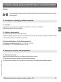
Contents
1. General information 4
2. Design and function 5
3. Safety 6
4. Transport, packaging and storage 9
5. Commissioning, operation 9
6. Faults 15
7. Maintenance and cleaning 17
8. Dismounting, return and disposal 17
9. Specifications 20

14247390.02 11/2019 EN/DE/FR/ES
4 WIKA operating instructions, pressure sensor, model A-1200
EN
1. General information
1. General information
■
The instrument described in the operating instructions has been designed and manufactured using state-of-the-
art technology. All components are subject to stringent quality and environmental criteria during production. Our
management systems are certied to ISO 9001 and ISO 14001.
■
These operating instructions contain important information on handling the instrument. Working safely requires that
all safety instructions and work instructions are observed.
■
Observe the relevant local accident prevention regulations and general safety regulations for the instrument's range
of use.
■
The operating instructions are part of the product and must be kept in the immediate vicinity of the instrument and
readily accessible to skilled personnel at any time. Pass the operating instructions on to the next operator or owner
of the instrument.
■
Skilled personnel must have carefully read and understood the operating instructions prior to beginning any work.
■
The general terms and conditions contained in the sales documentation shall apply.
■
Subject to technical modications.
■
Further information:
- Internet address: www.wika.de / www.wika.com
- Relevant data sheet: PE 81.90
- Application consultant: Tel.: +49 9372 132-0
Fax: +49 9372 132-406

14247390.02 11/2019 EN/DE/FR/ES
5WIKA operating instructions, pressure sensor, model A-1200
EN
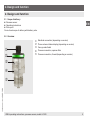
2. Design and function
2. Design and function
2.1 Scope of delivery
■
Pressure sensor
■
Operating instructions
■
Test report
Cross-check scope of delivery with delivery note.
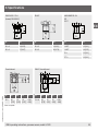
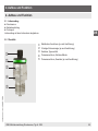
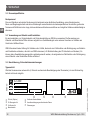
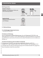
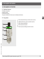
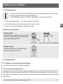
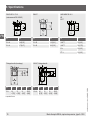
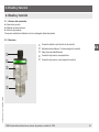
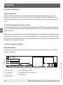
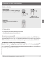
2.2 Overview
Electrical connection (depending on version)
Three-coloured status display (depending on version)
Case, product label
Process connection, spanner ats
Process connection, thread (depending on version)

14247390.02 11/2019 EN/DE/FR/ES
6 WIKA operating instructions, pressure sensor, model A-1200
EN
3. Safety
3. Safety
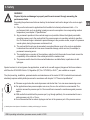
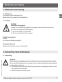
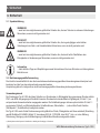
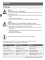
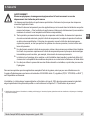
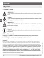
3.1 Explanation of symbols
WARNING!
... indicates a potentially dangerous situation that can result in serious injury or death, if not avoided.
CAUTION!
... indicates a potentially dangerous situation that can result in light injuries or damage to property or the
environment, if not avoided.
WARNING!
... indicates a potentially dangerous situation that can result in burns, caused by hot surfaces or liquids,
if not avoided.
Information
... points out useful tips, recommendations and information for ecient and trouble-free operation.
3.2 Intended use
The instrument has been designed and built solely for the intended use described here, and may only be used
accordingly.
The manufacturer shall not be liable for claims of any type based on operation contrary to the intended use.
Intended use
The model A-1200 pressure sensor is used for the switching of circuits as a function of the measured pressure
via a PNP or NPN output signal. In addition, the pressure value can be output to appropriate read-out units as a
standardised digital signal (IO-Link 1.1). The switching conditions can optionally be programmed using IO-Link 1.1
(switch and reset points, switching functions, time response, …) or congured using the teach function (switch point 1,
switching function).
The model A-1200 has been developed for the pressure measurement of non-hazardous uids, liquids and gases
(classication in accordance with Directive 2014/68/EU Article 13, Regulation (EC) No. 1272/2008, or GHS
1)
) which
are mainly used for cooling, lubrication, cleaning or power transmission in industrial machines.
1) Globally Harmonized System of Classication, Labelling and Packaging of Chemicals

14247390.02 11/2019 EN/DE/FR/ES
7WIKA operating instructions, pressure sensor, model A-1200
EN
3. Safety
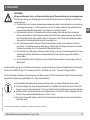
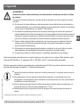
WARNING!
Physical injuries and damage to property and the environment through exceeding the
performance limits
Exceeding the performance limits can destroy the instrument and lead to danger in the end-use appli-
cation.
▶
Only use the instrument in applications that lie within its technical performance limits. → For
performance limits, such as derating (maximum current consumption at a corresponding medium
temperature), see chapter 9 “Specifications”.
▶
Any permanent operation in the overload range is not permitted. Above the highest permissible
operating pressure, up to the overload limit, the pressure sensor is operating outside its specifica-
tion. The overload range is intended to prevent damage to the pressure sensor, as part of a pressure
vessel system, during the pressure containment test.
▶
The overload limit must never be exceeded, even when failures occur in the end-use application.
Loads above the overload limit can cause irreversible damage, which can lead, for example, to
permanent measuring errors.
▶
The manufacturer or operator of the machine or plant in which the product is used must ensure the
compatibility of the materials of the wetted parts with the medium used.
▶
The pressure switch should not be used with abrasive or unstable fluids, in particular not with
hydrogen.
Special versions for oil and grease-free applications, as well as for use with oxygen (dangerous uid in accordance
with Directive 2014/68/EU Article 13, Regulation (EC) No. 1272/2008, or GHS
1)
), are available on request.
The (dis-)mounting, installation, parameterisation and maintenance of the model A-1200 in industrial environments
absolutely requires suitably skilled personnel in accordance with chapter 3.3. “Personnel qualication”.
■
Pressure surges below the nominal pressure and shorter than 1 ms can cause measuring errors.
■
For applications where pressure spikes can occur, the use of a restrictor is recommended. The
restrictor narrows the pressure port to 0.6 mm and thus increases the resistance against pressure
spikes.
■
With media that could block the pressure port (e.g. through particles), it is recommended to use a
wider pressure port of 6 or 12 mm.
■
It must be ensured that no atomic hydrogen can form in the pressure port of the pressure sensor.
1) Globally Harmonized System of Classication, Labelling and Packaging of Chemicals

14247390.02 11/2019 EN/DE/FR/ES
8 WIKA operating instructions, pressure sensor, model A-1200
EN
3.3 Personnel qualication
Skilled personnel
Skilled personnel, authorised by the operator, are understood to be personnel who, based on their technical training,
knowledge of measurement and control technology and on their experience and knowledge of country-specic regula-
tions, current standards and directives, are capable of carrying out the work described and independently recognising
potential hazards.
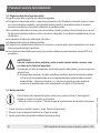
3.4 Use of accessories and spare parts
It is recommended to use original accessories and original spare parts from WIKA. Using accessories and spare parts
from third parties can lead to damage to the instrument or accidents, due to quality defects or other reasons.
WIKA assumes no liability for damage or accidents caused by a malfunction or unsuitability of accessories and spare
parts which do not originate from WIKA (e.g. non-compliance with the IP ingress protection of connectors). No warranty
claims can be made which arise due to a malfunction or unsuitability of any accessory or spare part from a third party.
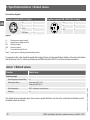
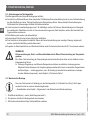
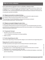
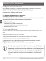
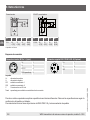
3.5 Labelling, safety marks
Product label
If the serial number becomes illegible (e.g. due to mechanical damage or overpainting), traceability will no longer be
possible.
IO-Link (option)
Coded date of manufacture
P# Product No.
Pin assignment and specications
S# Serial No.
Approvals
Measuring range
Symbols
Before mounting and commissioning the instrument, ensure you read the operating instructions!
A-1200
www.wika.com
Made in Germany
3. Safety

14247390.02 11/2019 EN/DE/FR/ES
9WIKA operating instructions, pressure sensor, model A-1200
EN
4. Transport, packaging and storage/5. Commissioning, operation
4. Transport, packaging and storage
4.1 Transport
Check the pressure sensor for any damage that may have been caused by transport.
Obvious damage must be reported immediately.
4.2 Packaging and storage
Do not remove packaging until just before mounting.
Keep the packaging as it will provide optimum protection during transport (e.g. change in installation site, sending for
repair).
Permissible conditions at the place of storage:
■
Storage temperature: -40 ... +70 °C [-40 ... +158 °F]
■
Humidity: 45 ... 75 % relative humidity (non-condensing)
5. Commissioning, operation
5.1 Checking the instrument
Prior to commissioning, the pressure sensor must be subjected to a visual inspection.
■
Leaking uid is indicative of damage.
■
Only use the pressure sensor if it is in perfect condition with respect to safety.
5.2 Requirements for mounting point
The mounting point must meet the following conditions:
■
Protected from weather inuences. Permanent exposure to UV light/sunlight can lead to a change in the colour of
the plastic parts and a clouding/yellowing of the status display. Therefore, a possible limitation of the visibility of the
status display cannot be excluded.
■
Under corrosive environmental conditions (such as salty, humid air), reductions in the gloss level of the metal
surfaces, or even corrosion on the instrument, may occur, which make readability of the product label more dicult.
■
Sealing faces are clean and undamaged.
■
Sucient space for a safe electrical installation.
■
The instrument is vented to the atmosphere. Therefore, no coating or other covering may be applied which might
restrict the venting.
■
For information on tapped holes and welding sockets, see Technical information IN 00.14 at www.wika.com.

14247390.02 11/2019 EN/DE/FR/ES
10 WIKA operating instructions, pressure sensor, model A-1200
EN
5. Commissioning, operation
WARNING!
Physical injuries and damage to property and the environment through running above or
below the temperature limits
Running above or below the temperature limits can destroy the instrument and lead to danger in the
end-use application.
▶
Permissible ambient and medium temperatures remain within the performance limits. Consider
possible restrictions on the ambient temperature range caused by mating connector used.
For performance limits, such as derating (maximum current consumption at a corresponding
medium temperature), see chapter 9 “Specifications”
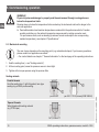
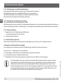
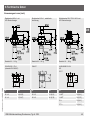
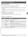
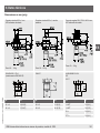
5.3 Mechanical mounting
The max. torque depends on the mounting point (e.g. material and shape). If you have any questions,
please contact our application consultant.
→ For contact details see chapter 1 “General information” or the back page of the operating instructions.
1. Seal the sealing face (→ see “Sealing variants”).
2
.
At the mounting point, screw the pressure sensor in hand-tight.
3
.
Tighten with a torque spanner using the spanner ats.
Sealing variants
Parallel threads
Seal the sealing face with flat gasket, lens-type
sealing ring or WIKA profile sealing.
per EN 837
per ISO 1179-2 (formerly DIN 3852-E)
Tapered threads
Wrap threads with sealing material
(e.g. PTFE tape).
NPT, R and PT

14247390.02 11/2019 EN/DE/FR/ES
11WIKA operating instructions, pressure sensor, model A-1200
EN
5. Commissioning, operation
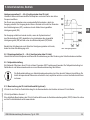
5.4 Electrical mounting
5.4.1 Requirements for voltage supply
→ For supply voltage see product label
For instruments without UL approval:
This equipment is intended for operation with low voltages which are separated from the AC 230 V (50 Hz) mains
voltage or voltages greater than AC 50 V or DC 120 V for dry environments. A connection to an SELV circuit is recom-
mended, or alternatively to circuits with a dierent protective measure in accordance with IEC 60364-4-41 installation
standard.
For instruments with UL approval and for use in North America:
The power supply for the pressure switch must be made via an energy-limited electric circuit in accordance with
section 9.4 of UL/EN/IEC 61010-1, or an LPS per UL/EN/IEC 60950-1/CSA C22.2 no. 60950-1, or class 2 in
accordance with UL1310/UL1585 (NEC or CEC). The voltage supply must be suitable for operation above 2,000 m
should the pressure switch be used at this altitude.
5.4.2 Requirements for electrical connection
■
Ingress protection of the mating connector corresponds to the ingress protection of the pressure sensor.
■
Cable diameter matches the cable bushing of the mating connector.
■
Cable gland and seals of the mating connector are correctly seated.
■
No humidity can ingress at the cable end.
5.4.3 Requirement for shielding and grounding
The pressure sensor must be grounded via the process connection.
When working during a running process operation, measures to prevent electrostatic discharge on the connection
terminals should be taken, as a discharge could lead to temporary corruption of the measured value.
5.4.4 Connecting the instrument
1. Assemble the mating connector or cable outlet.
→ For pin assignment see product label
2
.
Establish the plug connection.

14247390.02 11/2019 EN/DE/FR/ES
12 WIKA operating instructions, pressure sensor, model A-1200
EN
5.5 Teach function (optional)
With the teach function, the instrument can be congured by short-circuiting the teach pin with U-.
Setting the switch point and window values
To adopt the prevailing process pressure as a new switch point or high value (window).
Short-circuit the teach pin with U- for 2 ... 5 seconds.
▶
Blinking yellow: Teach mode for switch point active, remove short-circuit.
▶
Blinking green: New switch point adopted.
▶
Blinking red: Teach pin not short-circuited for long enough or error in teach process.
The reset point and the low value for the window function will be corrected automatically. The previously
set hysteresis (for default value, see Annex 1 “Default values”) or the dierence between the window
high and window low will be restored. In the event that the prevailing pressure is below 5 % of the
measuring range end value, no teach process will be carried out. Should the prevailing pressure be less
than the set hysteresis or the set window band, the reset point or the low value of the window function
will be set to the start of measuring range.
Setting the switching function
To change the switching function between normally open and normally closed.
Short-circuit the teach pin with U- for 10 ... 20 seconds.
▶
2 ... 5 seconds: Blinking yellow: Teach mode for switch point active, do not remove short-circuit.
▶
5 ... 10 seconds: Permanently lit yellow: Teach mode changes to switching function, do not remove short-circuit.
▶
10 ... 20 seconds: Blinking yellow: Teach mode for switching function active, remove short-circuit.
▶
> 20 seconds: Permanently lit yellow, teach process failed.
▶
Blinking green: Switching function changed.
▶
Blinking red: Teach pin not short-circuited for long enough or error in teach process.
5. Commissioning, operation

14247390.02 11/2019 EN/DE/FR/ES
13WIKA operating instructions, pressure sensor, model A-1200
EN
5. Commissioning, operation
5.6 Colour codes of status display
Colour Interval Description
Green Lit permanently Instrument is ready for operation, no error
Blinking (5 seconds) Teach successful
Yellow Blinking (continuously) Temporary error, operation outside of the specication (e.g. under- or overpressure,
under- or overtemperature).
Lit permanently Time exceeded, teach signal applied longer than 20 s
Blinking (during teach) Instrument blinks so long as the teach is running
Red Blinking (continuously) “Locate me” function active or permanent error; In case of a permanent error, the instru-
ment must be replaced
Blinking (5 seconds) Teach failed
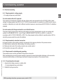
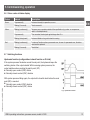
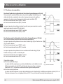
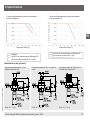
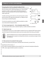
5.7 Switching functions
Hysteresis function (congurable via teach function or IO-Link)
If the system pressure uctuates around the set point, the hysteresis keeps the
switching status of the outputs stable. With increasing system pressure, the
output switches when reaching the switch point (SP).
■
Normally open contact (HNO): Active
■
Normally closed contact (HNC): Inactive
With system pressure falling again, the output will not switch back before the reset
point (RP) is reached.
■
Normally open contact (HNO): Inactive
■
Normally closed contact (HNC): Active
Fig.: Hysteresis function

14247390.02 11/2019 EN/DE/FR/ES
14 WIKA operating instructions, pressure sensor, model A-1200
EN
5. Commissioning, operation
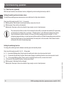
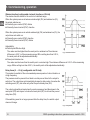
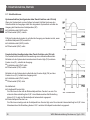
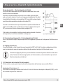
Window function (congurable via teach function or IO-Link)
The window function allows for the control of a dened range.
When the system pressure is between window high (FH) and window low (FL),
the output switches on.
■
Normally open contact (FNO): Active
■
Normally closed contact (FNC): Inactive
When the system pressure is outside window high (FH) and window low (FL), the
output does not switch on.
■
Normally open contact (FNO): Inactive
■
Normally closed contact (FNC): Active
Adjustability:
■
Switch point/Window High
The value must be higher than the reset point or window low. The minimum
dierence is 0.25 % of the measuring range. With a setting less than 0.25 %,
the reset point will be adjusted automatically.
■
Reset point/window low
The value must be lower than the switch point or window high. The minimum dierence is 0.25 % of the measuring
range. With a setting less than 0.25 %, the switch point will be adjusted automatically.
Delay times (0 … 65 s) (congurable via IO-Link)
This makes it possible to lter out unwanted pressure peaks of a short duration or
a high frequency.
The pressure must be present for at least a certain pre-set time for the output to
switch on. The output does not immediately change its status when it reaches the
switching event (SP), but rather only after the pre-set delay time (DS).
The output only switches back when the system pressure has fallen down to the
reset point (PR) and stays at or below the reset point (RP) for at least the pre-set
delay time (DR).
If the switching event is no longer present after the delay time, the switch output
does not change.
Fig.: Window function
Fig.: Delay times

14247390.02 11/2019 EN/DE/FR/ES
15WIKA operating instructions, pressure sensor, model A-1200
EN
5. Commissioning, operation/6. Faults
5.8 Damping function (0 ... 65 s) (congurable via IO-Link)
With this, the time span between a pressure change and the change of the switching state can be set.
5.9 Zero point setting
A zero point oset can be reset with the 0SET parameter via IO-Link. Only carry out zero point setting for gauge and
vacuum pressure measuring ranges at the start of the measuring range.
Carry out the zero point setting of absolute pressure measuring ranges at 0 bar absolute (vacuum).
Since appropriate references are required for this, we recommend that this is only carried out by the
manufacturer.
5.10 Description of the IO-Link functionality (optional)
IO-Link is a point-to-point connection for the communication of the instrument with an IO-Link master.
IO-Link specication: Version 1.1
A detailed description of the IO-Link functionality and the device description le (IODD) can be found online on the
product details page at www.wika.de.
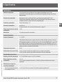
6. Faults
CAUTION!
Physical injuries and damage to property and the environment
If faults cannot be eliminated by means of the listed measures, the pressure sensor must be taken out of
operation immediately.
▶
Ensure that pressure or signal is no longer present and protect against accidental commissioning.
▶
Contact the manufacturer.
▶
If a return is needed, please follow the instructions given in chapter 8.2 “Return”.

14247390.02 11/2019 EN/DE/FR/ES
16 WIKA operating instructions, pressure sensor, model A-1200
EN
6. Faults
WARNING!
Physical injuries and damage to property and the environment caused by hazardous media
Upon contact with hazardous media (e.g. oxygen) and also with refrigeration plants and compressors,
there is a danger of physical injuries and damage to property and the environment.
▶
Should a failure occur, media with extremely high temperature and under high pressure or vacuum
may be present at the instrument.
▶
For these media, in addition to all standard regulations, the appropriate existing codes or regulations
must also be followed.
▶
Wear the requisite protective equipment.
For contact details see chapter 1 “General information” or the back page of the operating instructions.
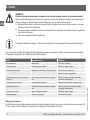
In the event of any faults, rst check whether the pressure sensor is mounted correctly, mechanically and electrically.
If complaint is unjustied, the handling costs will be charged.
Fault Possible cause Measure
No output signal Cable break Check the continuity
No output signal No/wrong supply voltage Rectify the supply voltage
No/wrong output signal Wiring error or switching of switching logic Observe the pin assignment
Check the output conguration
Constant output signal upon change in
pressure
Mechanical overload caused by overpres-
sure
Replace instrument; if it fails repeatedly,
contact the manufacturer
Deviating zero point signal Overload safety exceeded Observe the permissible overload safety
Signal span too small Mechanical overload caused by overpres-
sure
Replace instrument; if it fails repeatedly,
contact the manufacturer
Signal span too small Supply voltage too high/low Rectify the supply voltage
Signal span drops Moisture has entered Fit the cable correctly
Warnings and errors
Via the three-coloured status display, internal instrument warnings (yellow) and errors (red) are shown, see chapter 5.6
“Colour codes of status display”. An extended error diagnosis is possible via IO-Link.

14247390.02 11/2019 EN/DE/FR/ES
17WIKA operating instructions, pressure sensor, model A-1200
EN
7. Maintenance and cleaning
7.1 Maintenance
This pressure sensor is maintenance-free.
Repairs must only be carried out by the manufacturer.
7.2 Cleaning
CAUTION!
Unsuitable cleaning agents
Cleaning with unsuitable cleaning agents may damage the instrument and the product label.
▶
Do not use any aggressive cleaning agents.
▶
Do not use any hard or pointed objects.
▶
Do not use any abrasive cloths or sponges.
Suitable cleaning agents
■
Water
■
Conventional dishwashing detergent
Cleaning the instrument
Wipe the instrument surface using a soft, damp cloth.
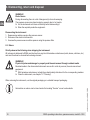
8. Dismounting, return and disposal
8.1 Dismounting
WARNING!
Physical injuries and damage to property and the environment caused by hazardous media
Upon contact with hazardous media (e.g. oxygen), there is a danger of physical injuries and damage to
property and the environment.
▶
Should a failure occur, media with extremely high temperature and under high pressure or vacuum
may be present at the instrument.
▶
Wear the requisite protective equipment.
7. Maintenance and cleaning

14247390.02 11/2019 EN/DE/FR/ES
18 WIKA operating instructions, pressure sensor, model A-1200
EN
8. Dismounting, return and disposal
WARNING!
Risk of burns
During dismounting there is a risk of dangerously hot media escaping.
The pressure sensor may have heated up severely due to hot media.
▶
Let the instrument cool down sufficiently before dismounting it.
▶
Wear the requisite protective equipment.
Dismounting the instrument
1. Depressurise and de-energise the pressure sensor.
2
.
Disconnect the electrical connection.
3
.
Unscrew the pressure sensor with a spanner using the spanner ats.
8.2 Return
Strictly observe the following when shipping the instrument:
All instruments delivered to WIKA must be free from any kind of hazardous substances (acids, bases, solutions, etc.)
and must therefore be cleaned before being returned.
WARNING!
Physical injuries and damage to property and the environment through residual media
Residual media in the dismounted instrument can result in a risk to persons, the environment and
equipment.
▶
With hazardous substances, include the material safety data sheet for the corresponding medium.
▶
Clean the instrument, see chapter 7.2 “Cleaning”.
When returning the instrument, use the original packaging or a suitable transport packaging.
Information on returns can be found under the heading “Service” on our local website.

14247390.02 11/2019 EN/DE/FR/ES
19WIKA operating instructions, pressure sensor, model A-1200
EN
8. Dismounting, return and disposal
8.3 Disposal
Incorrect disposal can put the environment at risk.
Dispose of instrument components and packaging materials in an environmentally compatible way and in accordance
with the country-specic waste disposal regulations.
Do not dispose of with household waste. Ensure a proper disposal in accordance with national regula-
tions.
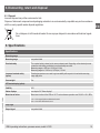
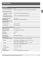
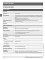
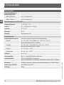
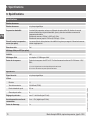
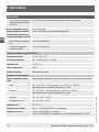
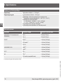
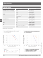
9. Specifications
Specications
Measuring range
Measuring range see product label
Overload safety The overload safety is based on the sensor element used. Depending on the selected process
connection and sealing, restrictions in overload safety can result.
Measuring ranges ≤ 600 bar (< 8,000 psi): 2-fold
Measuring ranges to 1.000 bar (≥ 8,000 psi): 1.5-fold
Increased overload safety
(option)
Deviating temperature errors and long-term stability with respect to the selected measuring
range apply here.
Vacuum-tight Yes
LED status display (option)
Visibility 360°
Status displays see chapter 5.6 “Status displays”
Mean time to failure Mean time to failure of the LEDs at 105 °C and continuous operation over 50,000 h: L50
1)
/ B50
2)
1) 50 % of the output light ux available after 50,000 h
2) 50 % of the LEDs failed after 50,000 h
Output signal
Output signal see product label

14247390.02 11/2019 EN/DE/FR/ES
20 WIKA operating instructions, pressure sensor, model A-1200
EN
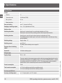
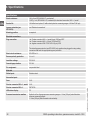
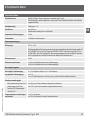
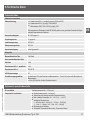
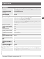
9. Specications
Specications
IO-Link
Revision 1.1
Transmission rate 38.4 kBaud (COM2)
Min. cycle time 2.3 ms
Master port class A
Zero point setting max. 3 % of span (via IO-Link)
Damping of switching outputs 0 ms ... 65 s (adjustable via IO-Link)
Switch-on time 1 s
Switching thresholds Switch point 1 and switch point 2 are individually adjustable via IO-Link.
Switch point 1 can be set to the prevailing pressure value using the teach function.
Switching functions Normally open, normally closed, window, hysteresis (adjustable via IO-Link)
The switching function of switch point 1 can be set to normally closed or normally open using
the teach function.
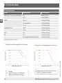
Switching voltage Supply voltage - 1 V
Switching current max. 250 mA
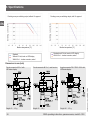
For details, see the derating curve on page 24
Response time of switching
output
≤ 5 ms
Service life 100 million switching cycles
Voltage supply
Supply voltage DC 10 ... 32 V
The power supply for the pressure sensor must be made via an energy-limited electric circuit in
accordance with section 9.3 of UL/EN/IEC 61010-1 or an LPS to UL/EN/IEC 60950-1 or class 2
in accordance with UL1310/UL1585 (NEC or CEC). The voltage supply must be suitable for
operation above 2,000 m should the pressure sensor be used at this altitude.
Current consumption 20 mA
Total current consumption ≤ 0.3 A incl. switching current (with one switching output)
≤ 0.6 A incl. switching current (with two switching outputs)
Accuracy specications
Accuracy, switching output ≤ ±1 % of span (option: ≤ ±0.5 % of span)
Seite wird geladen ...
Seite wird geladen ...
Seite wird geladen ...
Seite wird geladen ...
Seite wird geladen ...
Seite wird geladen ...
Seite wird geladen ...
Seite wird geladen ...
Seite wird geladen ...
Seite wird geladen ...
Seite wird geladen ...
Seite wird geladen ...
Seite wird geladen ...
Seite wird geladen ...
Seite wird geladen ...
Seite wird geladen ...
Seite wird geladen ...
Seite wird geladen ...
Seite wird geladen ...
Seite wird geladen ...
Seite wird geladen ...
Seite wird geladen ...
Seite wird geladen ...
Seite wird geladen ...
Seite wird geladen ...
Seite wird geladen ...
Seite wird geladen ...
Seite wird geladen ...
Seite wird geladen ...
Seite wird geladen ...
Seite wird geladen ...
Seite wird geladen ...
Seite wird geladen ...
Seite wird geladen ...
Seite wird geladen ...
Seite wird geladen ...
Seite wird geladen ...
Seite wird geladen ...
Seite wird geladen ...
Seite wird geladen ...
Seite wird geladen ...
Seite wird geladen ...
Seite wird geladen ...
Seite wird geladen ...
Seite wird geladen ...
Seite wird geladen ...
Seite wird geladen ...
Seite wird geladen ...
Seite wird geladen ...
Seite wird geladen ...
Seite wird geladen ...
Seite wird geladen ...
Seite wird geladen ...
Seite wird geladen ...
Seite wird geladen ...
Seite wird geladen ...
Seite wird geladen ...
Seite wird geladen ...
Seite wird geladen ...
Seite wird geladen ...
Seite wird geladen ...
Seite wird geladen ...
Seite wird geladen ...
Seite wird geladen ...
Seite wird geladen ...
Seite wird geladen ...
Seite wird geladen ...
Seite wird geladen ...
Seite wird geladen ...
Seite wird geladen ...
Seite wird geladen ...
Seite wird geladen ...
Seite wird geladen ...
Seite wird geladen ...
Seite wird geladen ...
Seite wird geladen ...
Seite wird geladen ...
Seite wird geladen ...
Seite wird geladen ...
Seite wird geladen ...
Seite wird geladen ...
Seite wird geladen ...
Seite wird geladen ...
Seite wird geladen ...
-
 1
1
-
 2
2
-
 3
3
-
 4
4
-
 5
5
-
 6
6
-
 7
7
-
 8
8
-
 9
9
-
 10
10
-
 11
11
-
 12
12
-
 13
13
-
 14
14
-
 15
15
-
 16
16
-
 17
17
-
 18
18
-
 19
19
-
 20
20
-
 21
21
-
 22
22
-
 23
23
-
 24
24
-
 25
25
-
 26
26
-
 27
27
-
 28
28
-
 29
29
-
 30
30
-
 31
31
-
 32
32
-
 33
33
-
 34
34
-
 35
35
-
 36
36
-
 37
37
-
 38
38
-
 39
39
-
 40
40
-
 41
41
-
 42
42
-
 43
43
-
 44
44
-
 45
45
-
 46
46
-
 47
47
-
 48
48
-
 49
49
-
 50
50
-
 51
51
-
 52
52
-
 53
53
-
 54
54
-
 55
55
-
 56
56
-
 57
57
-
 58
58
-
 59
59
-
 60
60
-
 61
61
-
 62
62
-
 63
63
-
 64
64
-
 65
65
-
 66
66
-
 67
67
-
 68
68
-
 69
69
-
 70
70
-
 71
71
-
 72
72
-
 73
73
-
 74
74
-
 75
75
-
 76
76
-
 77
77
-
 78
78
-
 79
79
-
 80
80
-
 81
81
-
 82
82
-
 83
83
-
 84
84
-
 85
85
-
 86
86
-
 87
87
-
 88
88
-
 89
89
-
 90
90
-
 91
91
-
 92
92
-
 93
93
-
 94
94
-
 95
95
-
 96
96
-
 97
97
-
 98
98
-
 99
99
-
 100
100
-
 101
101
-
 102
102
-
 103
103
-
 104
104


in anderen Sprachen
- français: WIKA A-1200 Mode d'emploi
- español: WIKA A-1200 Instrucciones de operación
Verwandte Artikel
-
WIKA PSD-4-ECO Bedienungsanleitung
-
WIKA PSD-4 Bedienungsanleitung
-
-
-
-
-
-
-
-