
Operating instructions
Betriebsanleitung
Mode d'emploi
Manual de instrucciones
EN
DE
FR
ES
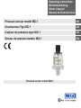
Pressure sensor model MG-1
Pressure sensor model MG-1
Drucksensor Typ MG-1
Capteur de pression type MG-1
Sensor de presion modelo MG-1

2 WIKA operating instructions, model MG-1
EN
DE
11609681.03 08/2019 EN/DE/FR/ES
FR
ES
© 2011 WIKA Alexander Wiegand SE & Co. KG
All rights reserved. / Alle Rechte vorbehalten.
WIKA
®
is a registered trademark in various countries.
WIKA
®
ist eine geschützte Marke in verschiedenen Ländern.
Prior to starting any work, read the operating instructions!
Keep for later use!
Vor Beginn aller Arbeiten Betriebsanleitung lesen!
Zum späteren Gebrauch aufbewahren!
Lire le mode d'emploi avant de commencer toute opération !
A conserver pour une utilisation ultérieure !
¡Leer el manual de instrucciones antes de comenzar cualquier trabajo!
¡Guardar el manual para una eventual consulta posterior!
Operating instructions model MG-1 Page 3 - 22
Betriebsanleitung Typ MG-1 Seite 23 - 42
Mode d'emploi type MG-1 Page 43 - 62
Manual de instrucciones modelo MG-1 Página 63 - 83

3WIKA operating instructions, model MG-1
11609681.03 08/2019 EN/DE/FR/ES
EN
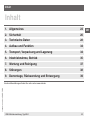
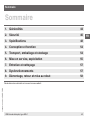
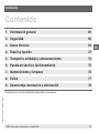
Contents
Contents
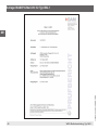
Declarations of conformity can be found online at www.wika.com.
1. General information 4
2. Safety 6
3. Specifications 8
4. Design and function 14
5. Transport, packaging and storage 14
6. Commissioning, operation 15
7. Maintenance and cleaning 17
8. Faults 17
9. Dismounting, return and disposal 18

4 WIKA operating instructions, model MG-1
11609681.03 08/2019 EN/DE/FR/ES
EN
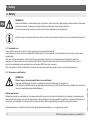
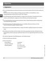
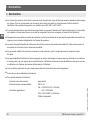
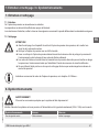
1. General information
1. General information
■
The pressure sensor described in the operating instructions has been designed and manufactured by state-of-the-
art technology. All components are subject to stringent quality and environmental criteria during production. Our
management systems are certied to ISO 9001 and ISO 14001.
■
These operating instructions contain important information on handling the pressure sensor. Working safely requires
that all safety instructions and work instructions are observed.
■
Observe the relevant local accident prevention regulations and general safety regulations for the pressure sensor's
range of use.
■
The operating instructions are part of the product and must be kept in the immediate vicinity of the pressure sensor
and readily accessible to skilled personnel at any time.
■
Skilled personnel must have carefully read and understood the operating instructions prior to beginning any work.
■
The manufacturer's liability is void in the case of any damage caused by using the product contrary to its intended
use, non-compliance with these operating instructions, assignment of insuciently qualied skilled personnel or
unauthorised modications to the pressure sensor.
■
The general terms and conditions contained in the sales documentation shall apply.
■
Subject to technical modications.
Further information:
- Internet address: www.wika.com
- Relevant data sheet: PE 81.44
- Application consultant: Tel.: +49 9372 132-0
Fax: +49 9372 132-406

5WIKA operating instructions, model MG-1
11609681.03 08/2019 EN/DE/FR/ES
EN
1. General information
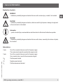
Explanation of symbols
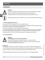
WARNING!
... indicates a potentially dangerous situation that can result in serious injury or death, if not avoided.
CAUTION!
... indicates a potentially dangerous situation, which can result in light injuries or damage to equipment
or the environment, if not avoided.
Information
… points out useful tips, recommendations and information for ecient and trouble-free operation.
CAUTION!
... indicates a potentially dangerous situation that can result in burns, caused by hot surfaces or liquids,
if not avoided.
Abbreviations
2-wire Two of the connection lines are used for the power supply.
The measurement signal also provides the supply current.
3-wire Two of the connection lines are used for the power supply.
One connection line is used for the measurement signal.
U
B
Positive power terminal
0V Negative power terminal
S
+
Positive measurement terminal

6 WIKA operating instructions, model MG-1
11609681.03 08/2019 EN/DE/FR/ES
EN
2. Safety
2. Safety
WARNING!
Before installation, commissioning and operation, ensure that the appropriate pressure sensor has been
selected in terms of measuring range, design and specic measuring conditions.
Non-observance can result in serious injury and/or damage to the equipment.
Further important safety instructions can be found in the individual chapters of these operating instructions.
2.1 Intended use
The pressure sensor is used to convert pressure into an electrical signal.
The pressure sensor has been designed and built solely for the intended use described here and may only be used
accordingly.
The technical specications contained in these operating instructions must be observed. Improper handling or
operation of the pressure sensor outside of its technical specications requires the instrument to be taken out of
service immediately and inspected by an authorised WIKA service engineer.
The manufacturer shall not be liable for claims of any type based on operation contrary to the intended use.
2.2 Personnel qualication
WARNING!
Risk of injury should qualication be insucient!
Improper handling can result in considerable injury and damage to equipment.
The activities described in these operating instructions may only be carried out by skilled personnel who
have the qualications described below.
Skilled personnel
Skilled personnel are understood to be personnel who, based on their technical training, knowledge of measurement
and control technology and on their experience and knowledge of country-specic regulations, current standards and
directives, are capable of carrying out the work described and independently recognising potential hazards.
Special operating conditions require further appropriate knowledge, e.g. of aggressive media.

7WIKA operating instructions, model MG-1
11609681.03 08/2019 EN/DE/FR/ES
EN
2. Safety
2.3 Special hazards
WARNING!
For hazardous media such as oxygen, acetylene, ammable or toxic gases or liquids, and refrigera-
tion plants, compressors, etc., in addition to all standard regulations, the appropriate existing codes or
regulations must also be followed.
WARNING
!
Residual media in dismounted instruments can result in a risk to persons, the environment and equipment.
Take sucient precautionary measures.
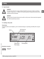
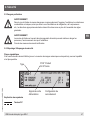
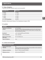
2.4 Labelling / safety marks
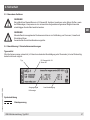
Product label
If the serial number becomes illegible (e.g. due to mechanical damage or overpainting), traceability will no longer be
possible.
Explanation of symbols
Voltage DC
Output signal
Pin assignment
Power supply
P# Product No.
S# Serial No.
Model

8 WIKA operating instructions, model MG-1
11609681.03 08/2019 EN/DE/FR/ES
EN
3. Specications
3. Specifications
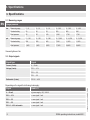
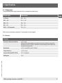
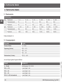
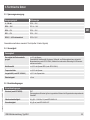
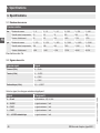
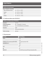
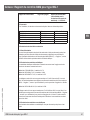
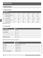
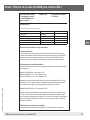
3.1 Measuring ranges
Gauge pressure
bar Measuring range 0 ... 6 0 ... 10 0 ... 16 0 ... 200 0 ... 300 0 ... 400
Overload safety 20 20 32 500 800 800
Burst pressure 25 25 160 1,200 1,700 1,700
psi Measuring range 0 ... 100 0 ... 150 0 ... 200 0 ... 3,000 0 ... 4,000 0 ... 5,000
Overload safety 290 290 460 7,200 11,000 11,000
Burst pressure 1,450 1,450 2,300 17,000 24,000 24,000
Vacuum tightness: Yes
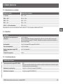
3.2 Output signals
Signal type Signal
Current (2-wire) 4 ... 20 mA
Voltage (3-wire) DC 0 ... 10 V
DC 0 ... 5 V
DC 1 ... 5 V
Ratiometric (3-wire) DC 0.5 ... 4.5 V
Depending on the signal the following loads apply:
Signal Load in Ω
4 ... 20 mA ≤ (power supply - 8 V) / 0.02 A
DC 0 ... 10 V > max. signal / 1 mA
DC 0 ... 5 V > max. signal / 1 mA
DC 1 ... 5 V > max. signal / 1 mA
DC 0.5 ... 4.5 V ratiometric > max. signal / 1 mA

9WIKA operating instructions, model MG-1
11609681.03 08/2019 EN/DE/FR/ES
EN
3. Specications
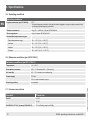
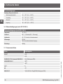
3.3 Voltage supply
The permissible power supply depends on the corresponding output signal.
Output signal Power supply
4 ... 20 mA DC 8 ... 30 V
DC 0 ... 10 V DC 14 ... 30 V
DC 0 ... 5 V DC 8 ... 30 V
DC 1 ... 5 V DC 8 ... 30 V
DC 0.5 ... 4.5 V ratiometric DC 5 ± 0.5 V
Total current consumption: maximum 10 mA (except for 2-wire signals)
3.4 Accuracy
Accuracy
Accuracy at reference conditions ≤ ±2 % of span
Including non-linearity, hysteresis, zero oset and end value deviation (corresponds to
measured error per IEC 61298-2). Calibrated in vertical mounting position with process
connection facing downwards.
Non-linearity ≤ ±0.5 % of span BFSL (per IEC 61298-8)
Temperature error ≤ ±2.0 % of span
Long-term drift (per IEC 61298-2) ≤ 0.3 % of span/year
Settling time ≤ 2 ms

10 WIKA operating instructions, model MG-1
11609681.03 08/2019 EN/DE/FR/ES
EN
3. Specications
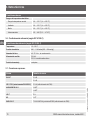
3.5 Operating conditions
Operating conditions
Ingress protection (per IEC 60529) IP67
The stated ingress protection only applies when plugged in using a mating connector that
has the appropriate ingress protection.
Vibration resistance 20 g (20 ... 2,000 Hz, 2 h) per IEC 60068-2-6
Shock resistance 40 g (6 ms) per IEC 60068-2-27
Permissible temperature ranges
Rated temperature range -20 ... +70 °C [-4 ... +158 °F]
Ambient -20 ... +70 °C [-4 ... +158 °F]
Medium -20 ... +70 °C [-4 ... +158 °F]
Storage -25 ... +80 °C [-13 ... +176 °F]
3.6 Reference conditions (per IEC 61298-1)
Reference conditions (per IEC 61298-1)
Temperature 15 ... 25 °C
Atmospheric pressure 860 … 1,060 mbar (665 ... 800 mmHg)
Air humidity 45 ... 75 % relative, non-condensing
Power supply DC 24 V
DC 5 V with ratiometric output
Mounting position as required
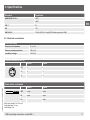
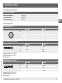
3.7 Process connections
Standard Thread size
EN 837 G ⅛ B
G ¼ B
DIN EN ISO 1179-2 (formerly DIN 3852-E) G ¼ A (Sealing ring from FKM)

11WIKA operating instructions, model MG-1
11609681.03 08/2019 EN/DE/FR/ES
EN
Standard Thread size
ANSI/ASME B1.20.1 ⅛ NPT
¼ NPT
ISO 7 R ¼
KS ¼ PT
SAE J514 E 7/16-20 UNF-2A, O-ring BOSS (Sealing ring from FKM)
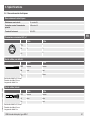
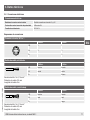
3.8 Electrical connections
Electrical safety
Short-circuit resistance S+ vs. 0V
Reverse polarity protection UB vs. 0V
Insulation voltage DC 500 V
Circular connector M12 x 1
2-wire 3-wire
U
B
1 1
0V 3 3
S
+
- 4
Cable outlet, unshielded
2-wire 3-wire
U
B
brown brown
0V green green
S
+
- white
Wire cross-section 3 x 0.14 mm
²
Cable diameter 3.2 mm
Cable length 2 m
3. Specications

12 WIKA operating instructions, model MG-1
11609681.03 08/2019 EN/DE/FR/ES
EN
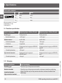
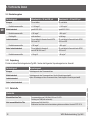
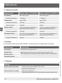
Cable outlet, shielded
2-wire 3-wire
U
B
brown brown
0V blue blue
S
+
- black
Wire cross-section 3 x 0.14 mm²
Cable diameter 4.3 mm
Cable length 2 m
3.9 Cleanliness specications
Level of cleanliness Measuring range < 30 bar [435 psi] Measuring range > 30 bar [435 psi]
Breathing gas Oil and grease free Oil and grease free
Residual hydrocarbons < 1,000 mg/m² < 1,000 mg/m²
Medical standard per ISO 15001 per ISO 15001
Residual hydrocarbons < 550 mg/m² < 220 mg/m²
Particle size not applicable on request
Industrial standard Oil and grease free for oxygen per ASTM G93
level D/E
Oil and grease free for oxygen per ASTM G93
level D/E
Residual hydrocarbons < 550 mg/m² < 220 mg/m²
High industrial standard Oil and grease free for oxygen per
ASTM G93 level C
Oil and grease free for oxygen per ASTM G93
level C
Residual hydrocarbons < 66 mg/m² < 66 mg/m²
3.10 Packaging
Level of cleanliness Type of packaging
Breathing gas Protection cap on the process connection
Medical standard Protection cap on the process connection, instrument sealed in a plastic bag
Option: Protection cap on the process connection, instrument sealed in two
plastic bags
Industrial standard
High industrial standard
3. Specications

13WIKA operating instructions, model MG-1
11609681.03 08/2019 EN/DE/FR/ES
EN
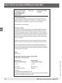
3.11 Materials
Materials
Wetted parts Process connection from stainless steel 316L and 13-8 PH
Sealing ring from FKM (if available)
Non-wetted parts Case from stainless steel 316L
Electrical connection from highly resistant, glass-bre reinforced plastic PBT GF 30
3.12 EU declaration of conformity
■
EMC directive, EN 61326 emission (group 1, class B) and immunity (industrial application)
■
Pressure equipment directive
■
RoHS directive
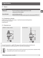
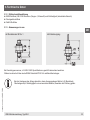
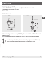
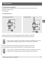
3.13 Dimensions in mm
For special model numbers, e. g. MG-10000, please note the specications stated on the delivery note.
For further specications, see WIKA data sheet PE 81.44 and the order documentation.
When designing the system, please note that the values given (e.g. burst pressure, overpressure safety)
are dependent upon the material, thread and gasket used.
with M12 x 1 circular connector with cable outlet
3. Specications

14 WIKA operating instructions, model MG-1
11609681.03 08/2019 EN/DE/FR/ES
EN
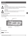
4. Design and function
4.1 Description
By means of a sensor element and by applying power, the prevailing pressure is converted into an amplied standar-
dised electrical signal via the deformation of a membrane. This electrical signal varies in proportion to the pressure and
can be evaluated accordingly.
4.2 Scope of delivery
Cross-check scope of delivery with delivery note.
5. Transport, packaging and storage
5.1 Transport
Check the pressure sensor for any damage that may have been caused during transportation.
Obvious damage must be reported immediately.
A recieved-goods inspection determines the purity of the pressure sensor. It is only guaranteed if the packaging is
undamaged or unopened.
5.2 Packaging
Do not remove packaging until just before mounting.
Keep the packaging as it will provide optimum protection during transport (e.g. change in installation site, sending for
repair).
5.3 Storage
Permissible conditions at the place of storage:
■
Storage temperature: -25 ... +80 °C
■
Humidity: 15 ... 95 % (no condensation)
Only ever store the pressure sensor in its original packaging.
WARNING!
Before storing the pressure sensor (following operation), remove any residual media. This is of particular
importance if the medium is hazardous to health, e.g. caustic, toxic, carcinogenic, radioactive, etc.
4. Design and function / 5. Transport, packaging and storage

15WIKA operating instructions, model MG-1
11609681.03 08/2019 EN/DE/FR/ES
EN
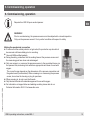
6. Commissioning, operation
Required tool: SW 24 open-ended spanner
WARNING!
Prior to commissioning, the pressure sensor must be subjected to a visual inspection.
Only use the pressure sensor if it is in perfect condition with respect to safety.
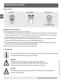
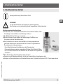
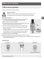
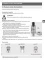
Making the mechanical connection
■
To ensure that the wetted parts do not get soiled, the protection cap should not
be removed until immediately prior to mounting.
■
Use only BAM-certied gaskets.
■
During mounting, make sure that the sealing faces at the pressure sensor and
the measuring point are clean and undamaged.
■
Only ever screw in, or unscrew, the pressure sensor to the prescribed torque via
the spanner-ats, and using tools which are appropriate and clean for use with
oxygen.
The correct torque depends on the dimensions of the process connection and
the gasket used (form/material). When screwing in or unscrewing the pressure
sensor, do not use the housing or plug for purchase.
■
When screwing in, do not cross the threads.
■
Only lubricate thread with materials approved for use with oxygen.
■
For information on tapped holes and welding sockets, please refer to our
Technical Information IN 00.14 at www.wika.com.
max.
20 Nm
6. Commissioning, operation

16 WIKA operating instructions, model MG-1
11609681.03 08/2019 EN/DE/FR/ES
EN
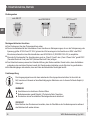
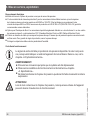
6. Commissioning, operation
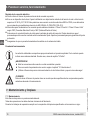
Types of sealing
per EN 837
per DIN 3852-E
NPT, R and PT
Self-sealing thread typ
Making the electrical connection
■
Ground the pressure sensor via the process connection.
■
This is Protection Class 3 equipment for connection at low voltages, which are separated from the power supply or
voltage by greater than AC 50 V or DC 120 V. Preferably, a connection to an SELV or PELV circuit is recommended;
alternatively protective measures from HD 60346-4-41 (DIN VDE 0100-410).
■
Option for North America: The connection can be made in line with “Class 2 Circuits” or “Class 2 Power Units” in
accordance with CEC (Canadian Electrical Code) or NEC (National Electrical Code).
■
Select a cable diameter that matches the cable gland of the plug. Make sure that the cable gland of the mounted
plug has a tight t. To guarantee the ingress protection, tighten the gland.
■
For cable outlets, make sure that no moisture enters at the cable end.
Functional check
The output signal must be proportional to the prevailing pressure. If this is not the case, this may indicate
a damaged membrane. In this case, see chapter “8. Faults”.
WARNING!
■
Only open the connections once the system has been depressurised
■
Observe the working conditions in accordance with chapter “3. Specications”.
■
Always operate the pressure sensor within the overpressure safety range.
CAUTION!
When touching the pressure sensor, please note that the surfaces of the device components can
become hot during operation.

17WIKA operating instructions, model MG-1
11609681.03 08/2019 EN/DE/FR/ES
EN
7. Maintenance and cleaning / 8. Faults
7. Maintenance and cleaning
7.1 Maintenance
This pressure sensor is maintenance-free.
Repairs must only be carried out by the manufacturer.
When performing maintenance work, the purity requirements of the applicable standards must be observed.
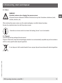
7.2 Cleaning
CAUTION!
■
Before cleaning, correctly disconnect the pressure sensor from the pressure supply, switch it o
and disconnect it from the mains.
■
Clean the pressure sensor with a moist cloth.
■
Wash or clean the dismounted pressure sensor before returning it in order to protect personnel
and the environment from exposure to residual media.
■
Residual media in dismounted pressure sensors can result in a risk to
persons, the environment
and equipment. Take sucient precautionary measures.
■
Do not use any pointed or hard objects for cleaning, as they may damage the membrane of the
process connection.
8. Faults
WARNING!
Open the connections only after the system has been depressurised!
First check whether the system is under pressure and whether the correct power supply and correct wiring type
(2-wire/3-wire) has been selected.
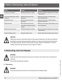
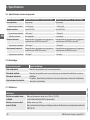
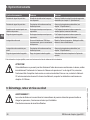
Faults Causes Measures
No output signal Cable break Check the through drilling
Deviating zero point signal Overpressure safety exceeded Observe the permissible overpressure safety (see
chapter "3. Specications")

18 WIKA operating instructions, model MG-1
11609681.03 08/2019 EN/DE/FR/ES
EN
8. Faults / 9. Dismounting, return and disposal
Faults Causes Measures
Deviating zero point signal Operating temperature too high/low Observe the permissible temperatures (see Chapter
"3. Specications")
Constant output signal upon change
in pressure
Mechanical overload caused by
overpressure
Replace pressure sensor; if it fails repeatedly,
contact the manufacturer
Signal span too small Mechanical overload caused by
overpressure
Replace pressure sensor; if it fails repeatedly,
contact the manufacturer
Signal span varies EMC interference sources in the
environment; for example, frequency
converter
Shield the pressure sensor; Cable shielding; remove
source of interference
Signal span varies/inaccurate Operating temperature too high/low Observe the permissible temperatures (see chapter
"3. Specications")
Signal span drops/too small Signal span drops/too small Contact manufacturer and replace pressure sensor
CAUTION!
If deciencies cannot be eliminated by means of the measures listed above, shut down the instrument
immediately, and ensure that pressure and/or signal are no longer present, and secure the instrument
from being put back into operation inadvertently. In this case, contact the manufacturer. If a return is
needed, please follow the instructions given in chapter “9.2 Return”.
9. Dismounting, return and disposal
WARNING!
Residual media in dismounted pressure sensors can result in a risk to persons, the environment and
equipment.
Take sucient precautionary measures.
9.1 Dismounting
WARNING!
Only disconnect the pressure sensor once the system has been depressurised!

19WIKA operating instructions, model MG-1
11609681.03 08/2019 EN/DE/FR/ES
EN
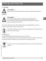
9.2 Return
WARNING!
Absolutely observe when shipping the pressure sensor:
All pressure sensors delivered to WIKA must be free from any kind of hazardous substances (acids,
leachate, solutions, etc.).
When returning the pressure sensor, use the original packaging or a suitable transport package.
Enclose the completed returns form with the pressure sensor.
Information on returns can be found under the heading „Service“ on our local website.
9.3 Disposal
Incorrect disposal may endanger the environment.
Dispose of instrument components and packaging materials in an environmentally compatible way and in accordance
with the country-specic waste disposal regulations.
Do not dispose of with household waste. Ensure a proper disposal in accordance with national regulations.
9. Dismounting, return and disposal

20 WIKA operating instructions, model MG-1
11609681.03 08/2019 EN/DE/FR/ES
EN
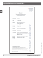
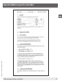
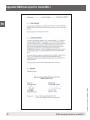
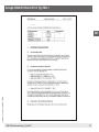
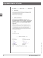
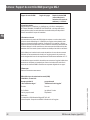
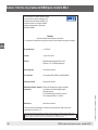
Appendix: BAM test report for model MG-1
Seite wird geladen ...
Seite wird geladen ...
Seite wird geladen ...
Seite wird geladen ...
Seite wird geladen ...
Seite wird geladen ...
Seite wird geladen ...
Seite wird geladen ...
Seite wird geladen ...
Seite wird geladen ...
Seite wird geladen ...
Seite wird geladen ...
Seite wird geladen ...
Seite wird geladen ...
Seite wird geladen ...
Seite wird geladen ...
Seite wird geladen ...
Seite wird geladen ...
Seite wird geladen ...
Seite wird geladen ...
Seite wird geladen ...
Seite wird geladen ...
Seite wird geladen ...
Seite wird geladen ...
Seite wird geladen ...
Seite wird geladen ...
Seite wird geladen ...
Seite wird geladen ...
Seite wird geladen ...
Seite wird geladen ...
Seite wird geladen ...
Seite wird geladen ...
Seite wird geladen ...
Seite wird geladen ...
Seite wird geladen ...
Seite wird geladen ...
Seite wird geladen ...
Seite wird geladen ...
Seite wird geladen ...
Seite wird geladen ...
Seite wird geladen ...
Seite wird geladen ...
Seite wird geladen ...
Seite wird geladen ...
Seite wird geladen ...
Seite wird geladen ...
Seite wird geladen ...
Seite wird geladen ...
Seite wird geladen ...
Seite wird geladen ...
Seite wird geladen ...
Seite wird geladen ...
Seite wird geladen ...
Seite wird geladen ...
Seite wird geladen ...
Seite wird geladen ...
Seite wird geladen ...
Seite wird geladen ...
Seite wird geladen ...
Seite wird geladen ...
Seite wird geladen ...
Seite wird geladen ...
Seite wird geladen ...
Seite wird geladen ...
-
 1
1
-
 2
2
-
 3
3
-
 4
4
-
 5
5
-
 6
6
-
 7
7
-
 8
8
-
 9
9
-
 10
10
-
 11
11
-
 12
12
-
 13
13
-
 14
14
-
 15
15
-
 16
16
-
 17
17
-
 18
18
-
 19
19
-
 20
20
-
 21
21
-
 22
22
-
 23
23
-
 24
24
-
 25
25
-
 26
26
-
 27
27
-
 28
28
-
 29
29
-
 30
30
-
 31
31
-
 32
32
-
 33
33
-
 34
34
-
 35
35
-
 36
36
-
 37
37
-
 38
38
-
 39
39
-
 40
40
-
 41
41
-
 42
42
-
 43
43
-
 44
44
-
 45
45
-
 46
46
-
 47
47
-
 48
48
-
 49
49
-
 50
50
-
 51
51
-
 52
52
-
 53
53
-
 54
54
-
 55
55
-
 56
56
-
 57
57
-
 58
58
-
 59
59
-
 60
60
-
 61
61
-
 62
62
-
 63
63
-
 64
64
-
 65
65
-
 66
66
-
 67
67
-
 68
68
-
 69
69
-
 70
70
-
 71
71
-
 72
72
-
 73
73
-
 74
74
-
 75
75
-
 76
76
-
 77
77
-
 78
78
-
 79
79
-
 80
80
-
 81
81
-
 82
82
-
 83
83
-
 84
84


in anderen Sprachen
- français: WIKA MG-1 Mode d'emploi
- español: WIKA MG-1 Instrucciones de operación
Verwandte Artikel
-
WIKA O-10 Bedienungsanleitung
-
-
-
-
-
-
-
-
WIKA PSD-4-ECO Bedienungsanleitung
-