Seite wird geladen ...

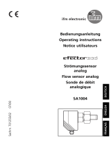
Bedienungsanleitung
Operating instructions
Notice utilisateurs
Strömungswächter
Flow monitor
Contrôleur de débit
SA3000
SA3001
R
DEUTSCHENGLISHFRANÇAIS
Sachnr. 701083/06 06/01

2
DEUTSCH
Inhalt
1. Bestimmungsgemäße Verwendung . . . . . . . . . . . . Seite 4
2. Bedien- und Anzeigeelemente . . . . . . . . . . . . . . . . Seite 4
3. Montage . . . . . . . . . . . . . . . . . . . . . . . . . . . . . . . Seite 5
4. Elektrischer Anschluß . . . . . . . . . . . . . . . . . . . . . . Seite 7
5. Einstellen der Schaltpunkte . . . . . . . . . . . . . . . . . . Seite 8
7. Inbetriebnahme / Betrieb / Wartung . . . . . . . . . . . . Seite 9
ENGLISH
Contents
1. Function and features . . . . . . . . . . . . . . . . . . . . . page 10
2. Controls and visual indication . . . . . . . . . . . . . . . page 10
3. Installation . . . . . . . . . . . . . . . . . . . . . . . . . . . . . page 11
4. Electrical connection . . . . . . . . . . . . . . . . . . . . . . page 13
5. Setting the switch points . . . . . . . . . . . . . . . . . . . page 14
6. Installation and set-up / operation / maintenance . page 15
FRANÇAIS
Contenu
1. Fonctionnement et caractéristiques . . . . . . . . . . . page 16
2. Eléments de service et d’indication . . . . . . . . . . . . page 16
3. Montage . . . . . . . . . . . . . . . . . . . . . . . . . . . . . . page 17
4. Raccordement électrique . . . . . . . . . . . . . . . . . . . page 19
5. Réglage des seuils . . . . . . . . . . . . . . . . . . . . . . . . page 20
6. Mise en service / Fonctionnement / Maintenance . page 21

3
Maßzeichnung - Scale drawing - Dimensions
M12x1
41
LED
Set / Enter
72
M16x1,5
95
48,5
7
60
52
11
M12x1
14
27
2
1
26,5
38,5
29,5
27
20
1: O-Ring
2: Druckscheibe
1: O-ring
2: compression washer
1: joint torrique
2: rondelle de pression

1. Bestimmungsgemäße Verwendung
Der Strömungswächter erfaßt die Strömungsgeschwindigkeit von
Wasser.
Zwei Schaltausgänge geben Signal, wenn die jeweils eingestellte
Strömungsgeschwindigkeit erreicht ist.
Zusätzlich zeigt das Gerät die aktuelle Strömungsgeschwindigkeit
durch eine LED-Kette an.
•Für Rohrleitungen mit Nennweiten DN 40 ... DN 100.
Typischer Meßfehler für Medium
Wasser bei verschiedenen
Mediumstemperaturen.
2. Bedien- und Anzeigeelemente
4
0
80 °C
25 °C
10 °C
V min. V max.
Strömung
max. neg.
Fehler 10%
des Endwerts
max. pos.
Fehler 10%
des Endwerts
0
15
30
45
60
75
90
105
120
135
150
Flow
SET S1
ENTER S2
Run-
mode
Prog-Mode 3 6 912
[cm/sec] SET S2
ENTER S1
Schaltpunkte S1 und S2
anzeigen, einstellen, bestätigen
10%-Skala
LED-Kette
2%-Skala

3. Montage
Um Fehlfunktionen zu vermei-
den, müssen Mindestabstände
zwischen Strömungswächter
und Krümmungen, Ventilen,
Reduzierungen u. ä. eingehalten
werden.
•Mind. 5 mal Rohrdurchmesser
an der Anströmseite (A).
•Mind. 3 mal Rohrdurchmesser
an der Abströmseite (B).
(Die Angaben gelten für lamina-
re Strömungsverhältnisse).
Schritt 1
Schweißen Sie die Einschweiß-
muffe in die Rohrleitung.
Einbautiefe je nach
Rohrwandstärke; d. h. bis zu der
Markierung, deren Nummer
gleich der Wandstärke ist. Die
Markierung muß mit der Rohr-
Außenwand abschließen und
umlaufend sichtbar sein.
Bei waagerecht verlaufenden
Rohren sollte die Muffe in einem
Winkel von 45° eingesetzt wer-
den.
5
DEUTSCH
4
4
6
10
8
10
4
8
6
45°
45°
D
A
B
min.
5 x D
min.
3 x D

Schritt 2
Setzen Sie den Strömungs-
wächter mit Kontermutter,
O-Ring und Druckscheibe in die
Muffe ein und schrauben Sie ihn
bis zum Anschlag ein.
Schritt 3
Richten Sie den Strömungs-
wächter aus (in Rohrlängsachse
oder quer dazu) und ziehen Sie
die Kontermutter fest.
6
O-Ring
Kontermutter
Druckscheibe

4. Elektrischer Anschluß
Das Gerät darf nur von einer Elektrofachkraft installiert werden.
Befolgen Sie die nationalen und internationalen Vorschriften zur
Errichtung elektrotechnischer Anlagen.
Spannungsversorgung nach EN50178, SELV, PELV.
Um die "limited Voltage" Anforderungen gemäß UL 508 zu
erfüllen, muß das Gerät aus einer galvanisch getrennten Quelle
versorgt und durch eine Überstromeinrichtung abgesichert werden.
Schalten Sie die Anlage spannungsfrei und schließen Sie das
Gerät an.
Anschlußbelegung:
Nach dem Einschalten der Versorgungsspannung leuchten alle LEDs
auf und verlöschen wieder schrittweise.* Danach ist das Gerät
betriebsbereit.
*Während dieser Zeit sind beide Ausgänge geschaltet (= EIN).
7
DEUTSCH
L
L+
3 BU
2 WH
4 BK
1 BN
S2 S1
L
L+
3 BU
2 WH
4 BK
1 BN
S1 S2
Adernfarben bei ifm-Kabeldosen:
1 = BN (braun), 2 = WH (weiß), 3 = BU (blau), 4 = BK (schwarz).
pnp-Geräte npn-Geräte

5. Einstellen der Schaltpunkte
Anzeige:
8
*Schaltpunkt verringern: Lassen Sie blinkende und leuchtende LED bis zum
maximalen Einstellwert laufen. Danach beginnt der Durchlauf wieder bei
dem minimalen Einstellwert.
1
Der aktuelle Schaltpunkt wird in
2%-Auflösung angezeigt
(hier: 30 + 6 = 36 cm/s),
nach 5s wird der Wert erhöht*
(schrittweise durch Einzeldruck
oder kontinuierlich durch
Festhalten der Taste).
Hier: 36 - 39 - 42 cm/s
Der eingestellte Wert wird
wirksam;
das Gerät springt zurück
in den Betriebsmodus.
Drücken Sie die Taste und
halten Sie sie gedrückt
(hier: S1 einstellen).
YE
YE
0
15
30
45
60
75
90
105
120
135
150
36912
YE
YE
GN
0
15
30
45
60
75
90
105
120
135
150
36912
Drücken Sie kurz
(= Bestätigung für S1).
2
Grüne LED = letzter angezeigter Strömungswert
leuchtende LED = 10%-Wert
des Schaltpunkts gelb (YE) = Ausgang
geschaltet;
rot (RD) = Ausgang nicht
geschaltet
blinkende LED = 2%-Wert des
Schaltpunkts
GN
YE
YE
RD
RD

Verriegeln / Entriegeln
Das Gerät läßt sich elektronisch verriegeln, so daß unbeabsichtigte
Fehleingaben verhindert werden: Drücken Sie 10s lang die beiden
Einstelltasten. Die Anzeige verlöscht kurzzeitig (= Bestätigung des
Verriegelns / Entriegelns).
Auslieferungszustand: Nicht verriegelt.
6. Inbetriebnahme / Betrieb / Wartung
Prüfen Sie nach Montage, elektrischem Anschluß und
Programmierung, ob das Gerät sicher funktioniert.
Nach dem Einschalten der Versorgungsspannung leuchten alle LEDs
auf und verlöschen wieder schrittweise.* Danach ist das Gerät
betriebsbereit.
*Während dieser Zeit sind beide Ausgänge geschaltet (= EIN).
Betriebsanzeige
Störanzeigen während des Betriebs
5 LEDs links blinken bei Kurzschluß in Schaltausgang S1; 5 LEDs rechts
blinken bei Kurzschluß in Schaltausgang S2.
Reinigungshinweis
Überprüfen Sie die Sensorspitze von Zeit zu Zeit auf Ablagerungen.
Reinigen Sie sie gegebenenfalls mit einem weichen Tuch. Fest anhaf-
tende Ablagerungen (z. B. Kalk) lassen sich mit handelsüblichem
Essigreiniger entfernen.
9
DEUTSCH
Grüne LEDs = aktuelle
Strömung (hier 90 - 105 cm/s).
1. LED blinkt = keine Strömung
GN
Gelbe LED = Schaltpunkt /
Ausgang geschaltet
hier: Ausgang 1 geschaltet
YE
Rote LED = Schaltpunkt /
Ausgang nicht geschaltet
hier: Ausg. 2 nicht geschaltet
RD GN
36912
GN
YE
GN
GN
GN
GN
GN
RD
0
15
30
45
60
75
90
105
120
135
150

1. Functions and features
The flow monitor detects the flow velocity of water.
Two switching outputs provide a signal if the respectively set flow
velocity has been reached.
In addition a row of LED’s indicates the current flow velocity.
•For pipes with nominal widths between DN 40 ... DN 100.
Typical measurement errors for
water and different temperatures
of the medium.
2. Controls and visual indication
10
0
80 °C
25 °C
10 °C
V min. V max.
flow
max. neg.
error 10 %
of the end value
max. pos.
error 10 %
of the end value
0
15
30
45
60
75
90
105
120
135
150
Flow
SET S1
ENTER S2
Run-
mode
Prog-Mode 3 6 912
[cm/sec] SET S2
ENTER S1
indication, adjustment and
acknowledgement of the
switch points S1 and S2
10% steps
row of LED’s
2% steps

3. Mounting
To avoid malfunction a minimum
distance between the flow moni-
tor and bends, valves, changes in
cross-section or such like must be
observed:
•Min. 5 x pipe diameter
upstream (A),
•min. 3 x pipe diameter down-
stream (B).
(This information refers to laminar
flow.)
Step 1
Weld the adapter into the pipe.
The installation depth depends
on the pipe wall thickness. The
bush should be inserted so that
the figure corresponding to the
wall thickness is flush with the
outside pipe wall and can be seen
fromall sides.
In the case of horizontal pipes
the bush should be welded at an
angle of 45°.
11
ENGLISH
4
4
6
10
8
10
4
8
6
45°
45°
D
A
B
min.
5 x D
min.
3 x D

Step 2
Insert the flow monitor with lock
nut, O-ring seal and compression
washer into the bush and screw
it in completely using the full
thread.
Step 3
Position the flow monitor (in the
longitudinal pipe axis or trans-
verse to it) and fasten the lock
nut.
12
O-ring seal
lock nut
compr. washer

4. Electrical connection
The unit must only be mounted by an electrician.
The national and international regulations for the installation of
electrical equipment must be observed.
Voltage supply to EN50178, SELV, PELV.
The device shall be supplied from an isolating source and
protected by an overcurrent device such that the limited voltage
circuit requirements in accordance with UL 508 are met.
Disconnect power before connecting the unit.
Wiring:
When the supply voltage is applied, all LEDs light and go off one after
the other.* The unit is then ready for operation.
*During this time both outputs are switched (= ON).
13
ENGLISH
Core colours of ifm sockets:
1 = BN (brown), 2 = WH (white), 3 = BU (blue), 4 = BK (black).
L
L+
3 BU
2 WH
4 BK
1 BN
S2 S1
L
L+
3 BU
2 WH
4 BK
1 BN
S1 S2
pnp units npn units

5. Setting the switch points
Display:
14
*Decrease the switch point: Let the flashing and lit LEDs move to the maximum
setting value. Then the cycle starts again at the minimum setting value.
1
The current switch point is
indicated in steps of 2%
(here: 30 + 6 = 36 cm/s),
after 5s the value is increased*
(incremental by pressing briefly or
scrolling by holding pressed).
Here: 36 - 39 - 42 cm/s
The set value becomes effective;
the unit is reset to the operating
mode.
Press the button and
keep it pressed
(here setting of S1).
YE
YE
0
15
30
45
60
75
90
105
120
135
150
36912
YE
YE
GN
0
15
30
45
60
75
90
105
120
135
150
36912
Press for a short time
(= acknowledgement for S1).
2
LED green = last flow value indicated
lit LED = 10% value of the
switching point yellow (YE) = output switched;
red (RD) = output not switched
flashing LED = 2% value of
the switching point
GN
YE
YE
RD
RD

Locking/unlocking
The unit can be electronically locked to prevent unwanted adjustment
of the set parameters: Press both setting buttons for 10s. Indication
goes out briefly (acknowledgement of locking / unlocking). Units are
delivered from the factory in the unlocked state.
6. Installation and set-up / operation / maintenance
After mounting, wiring and setting check whether the unit operates
correctly.
When the supply voltage is applied, all LEDs light and go off one after
the other.* The unit is then ready for operation.
*During this time both outputs are switched (= ON).
Indication in the operating mode
Faults displayed during operation:
5 left LED’s flashing in case of short-circuit at the switching output S1;
5 right LED’s flashing in case of short-circuit at the switching output
S2.
Recommended maintenance
Check the sensor tip for build-up from time to time. Clean it with a
soft cloth. If necessary, build-up which adheres firmly (e.g. lime) can
be removed with a common vinegar cleansing agent.
15
ENGLISH
LED’s green = current flow rate
(here: 90 - 105 cm/s).
1st LED flashes = no flow
GN
yellow LED = switch point /
output switched
here: output 1 switched
YE
red LED = switch point / output
not switched
here: output 2 not switched
RD GN
36912
GN
YE
GN
GN
GN
GN
GN
RD
0
15
30
45
60
75
90
105
120
135
150

1. Fonctionnement et caractéristiques
Le contrôleur de débit détecte la vitesse de circulation de l'eau.
Deux sorties de commutation fournissent un signal si la vitesse du
fluide réglée est atteinte.
De plus, une rampe de LED affiche la vitesse actuelle du fluide.
•Pour des tubes de diamètre nominal DN40 à DN100.
Erreur de mesure typique pour
l’eau à différentes températures
du fluide.
2. Eléments de service et d’indication
16
0
80 °C
25 °C
10 °C
V min. V max.
vitesse du fluide
erreur max.
neg. 10 % de
la valeur finale
erreur max.
pos. 10 % de
la valeur finale
0
15
30
45
60
75
90
105
120
135
150
Flow
SET S1
ENTER S2
Run-
mode
Prog-Mode 3 6 912
[cm/sec] SET S2
ENTER S1
visualisation, réglage
et confirmation des seuils
S1 et S2
en pas de 10%
rampe de LED
en pas de 2%

3. Montage
Afin d’éviter un mauvais fonction-
nement une distance minimum
doit être respectée entre la sonde
et les coudes, vannes, change-
ments de section, etc.
•Min. 5 x diamètre de la canali-
sation en amont (A),
•min. 3 x diamètre de la canali-
sation en aval (B).
(Les données se réfèrent aux
fluides à l'état laminaire).
Pas 1
Souder l'adaptateur sur le tube.
La profondeur d’installation
dépend de l’épaisseur de la paroi
du tube. Le numéro relatif à
l’épaisseur de la paroi doit être à
fleur avec la paroi extérieure du
tube et visible de tous les côtés.
Sur les tubes horizontaux, le
raccord doit être soudé avec un
angle de 45°.
17
FRANÇAIS
4
4
6
10
8
10
4
8
6
45°
45°
D
A
B
min.
5 x D
min.
3 x D

Pas 2
Insérer le détecteur de circulation
de fluides avec contre-écrou, joint
torique et rondelle de pression
dans le raccord à souder et le visser
jusqu'à la batée.
Pas 3
Positionner le détecteur de circu-
lation de fluides (dans l’axe du
tube ou perpendiculairemen) et
serrer le contre-écrou.
18
joint torique
contre-écrou
rond. de pres.

4. Raccordement électrique
L'appareil ne doit être monté que par un électricien.
Les règlements nationaux et internationaux relatifs à l'installation
de matériel électrique doivent être respectés.
Alimentation selon EN50178, TBTS, TBTP.
Afin de répondre aux exigences de la norme "UL 508" pour la
catégorie "limited voltage", l´appareil doit être impérativement
alimenté par une alimentation isolée galvaniquement et équipée
d´un dispositif de protection contre les surcharges.
Mettre l’installation hors tension avant le raccordement.
Raccordement:
Dès la mise sous tension toutes les LED s'allument et s'éteignent l'une
après l'autre.* L'appareil est ensuite opérationnel.
*Durant ce temps les deux sorties sont commutées (= ON).
19
FRANÇAIS
Couleurs des fils conducteurs des connecteurs femelles ifm:
1 = BN (brun), 2 = WH (blanc), 3 = BU (bleu), 4 = BK (noir).
L
L+
3 BU
2 WH
4 BK
1 BN
S2 S1
L
L+
3 BU
2 WH
4 BK
1 BN
S1 S2
appareils pnp appareils npn

5. Réglage des seuils
Affichage:
20
*Réduire le seuil: Laissez les LED clignotante et allumée passer la valeur de réglage
maximum. Ensuite le cycle recommence à la valeur de réglage minimum.
1
La valeur actuelle est indiqué
en pas de 2%
(ici: 30 + 6 = 36 cm/s),
après 5s la valeur est incrémentée*
(pas à pas en appuyant sur le
bouton plusieurs fois ou continuelle-
ment en le maintenant appuyé).
Ici: 36 - 39 - 42 cm/s
La valeur réglée devient efective;
l'appareil est remis en mode de
fonctionnement.
Appuyer sur le bouton et le
maintenir appuyé
(ici: régler S1).
YE
YE
0
15
30
45
60
75
90
105
120
135
150
36912
YE
YE
GN
0
15
30
45
60
75
90
105
120
135
150
36912
Appuyer brièvement
(= confirmation pour S1).
2
LED verte = dernière valeur du débit affichée
LED allumée = 10% valeur du
seuil jaune (YE) = sortie commutée;
rouge (RD) = sortie pas com-
mutée;
LED clignotante = 2% valeur
du seuil
GN
YE
YE
RD
RD
/