Seikom Electronic NLSW45-4 Installation and Operating Instruction
- Typ
- Installation and Operating Instruction

Schaltpunkteinstellung
Der Zusammenhang zwischen Luftgeschwindigkeit und Widerstandsänderung ist nicht linear. Im unteren Bereich
(kleine Strömungen) ist die Änderung des Messwertes sehr groß. Im oberen Bereich wird die Messwertänderung bei
gleichen Strömungsänderungen immer geringer. Bei der Einstellung des Schaltpunktes sollte beachtet werden, welche
Änderung überwacht werden soll. Es sollen folgende Anforderungen betrachtet werden:
Geringe Strömungsänderung im hohen Strömungsgeschwindigkeitsbereich: Der Schaltpunkt sollte sehr nah am
Messwert der Normalströmung gewählt werden, da die Messwertänderung bei Strömungsänderung sehr gering ist. Da
die Temperaturkompensation eine gewisse Verzögerung gegenüber der tatsächlichen Temperaturänderung aufweist,
ist eine solche Schaltpunkteinstellung nur bei Anwendungen mit langsamen Temperaturänderungen möglich.
Geringe Strömungsänderung im niedrigen Strömungsgeschwindigkeitsbereich: Der Schaltpunkt kann mit einem
größeren Abstand zum Messwert der Normalströmung gewählt werden, da die Messwertänderung bei
Strömungsänderung groß ist. Eine Temperaturänderung wirkt sich nicht auf das Schaltverhalten aus.
Große Strömungsänderung: Hier ist meist eine Ja/Nein-Aussage gewünscht (z.B. Pumpe läuft oder Pumpe steht).
Es kann daher ein so großer Sicherheitsabstand gewählt werden, dass weder Temperaturänderungen noch
Verwirbelungen einen Einfluss auf das Schaltverhalten haben.
Inbetriebnahme
Der Anschluss und die Inbetriebnahme muss vom Fachpersonal vorgenommen werden!
Bei der Inbetriebnahme und Einstellung der Geräte ist folgende Vorgehensweise zweckmäßig:
1. Strömungswächter gemäß Einbaubedingungen installieren und elektrisch anschließen.
2. Passenden Fühler anschließen (F6.1-F6.5). Achtung! Vertauschen der Fühleranschlüsse führt zu
Fehlfunktionen und ggf. zu Beschädigungen.
3. Trimmer „fein“ und „grob“ auf Minimale Empfindlichkeit einstellen (Linksanschlag).
4. Netzspannung anlegen; Die grüne LED leuchtet. Das Gerät ist innerhalb von wenigen Sekunden betriebsbereit.
5. Strömungserzeuger einschalten.
6. Trimmer „grob“ langsam in Richtung Maximum drehen, bis die gelbe LED leuchtet und das Ausgangsrelais
anzieht. Um stabile Schaltverhältnisse zu erreichen, sollten Sie mit dem Trimmer „fein“ den Schaltpunkt nach 2
bis 3Minuten kontrollieren und leicht über den Schaltpunkt hinwegdrehen.
7. Zur Überprüfung der Strömungsüberwachung, Strömungserzeugung reduzieren oder ausschalten. Die gelbe
LED erlischt und das Ausgangsrelais fällt ab.
8. Glykolgehalt überprüfen (unter 30% ?)
Das Gerät ist jetzt auf Überwachungsfunktion eingestellt.
Was tun, wenn Ihr Strömungswächter nicht funktioniert
Problem
Ursache
Lösung
NLSW45-4 funktioniert überhaupt nicht
Keine oder falsche Netzspannung
angeschlossen
Netzspannung und Anschluß
überprüfen
NLSW45-4 erkennt Strömung nicht
Sensor ist nicht richtig installiert
Messbereich entspricht nicht den
technischen Daten
Glykolgehalt größer als 30% ?
Einbaubedingungen überprüfen
Rohrquerschnitt verändern
Glykolgehalt unter 30% reduzieren
NLSW45-4 hat verändertes
Ansprechverhalten
Sensor ist durch das Medium stark
verschmutzt (Ablagerungen
Glykolgehalt größer als 30% ?
Sensor mit Wasser vorsichtig
reinigen
Glykolgehalt unter 30% reduzieren
NLSW45-4 schaltet bei schneller
Mediumstemperaturerhöhung
Temperaturgradient ist außerhalb
der technischen Daten
Poti „Empfindlichkeit“ etwas weiter
im Uhrzeigersinn drehen.
Temperaturgradienten überprüfen
Gerät bei heissem Medium einstellen
Irrtümer und Druckfehler sind nicht auszuschließen. Alle Angaben „ohne Gewähr“. Stand 08/2018
SEIKOM-Electronic GmbH & Co. KGFortunastr.20D-42489 Wülfrath
Telefon: +49(0) 20 58/20 44 Fax: +49(0) 20 58 / 79 111
E-Mail: info@seikom-electronic.com Internet: http://www.seikom-electronic.de
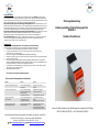
Strömungsüberwachung
Bedienungsanleitung für die Strömungswächter
NLSW45-4
Medium Luft und Wasser
Unsere Produkte entsprechen den Anforderungen der europäischen Richtlinien
WEEE-Richtlinie 2012/19/EU – RoHS-Richtlinie 2011/65/EU

Die Auswerteelektronik NLSW45-4 überwacht Luftströmungen + Wasserkreisläufe in Verbindung mit den
Fühlern F6.1, F6.2, F6.3, F6.4 und F6.5 auf unterschreiten eines stufenlos einstellbaren Schaltpunktes. Die
Sensorleitung wird auf Kurzschluss und Drahtbruch überwacht.
Als Ausgangssignal steht ein potentialfreier Wechslerkontakt zur Verfügung.
Der Sensor kann mit geringen Aufwand installiert werden und besitzt keine mechanisch bewegten Teile, die
verschleißen könnten. Als Ersatz für mechanische Paddelwächter geeignet !
Funktionsweise
Die Strömungswächter der Typenreihe NLSW45-4 arbeiten nach dem kalorimetrischen Prinzip.
Die Geräte schalten bei Erreichen eines eingestellten Schwellwertes. Beim kalorimetrischen Messprinzip wird ein
temperaturempfindlicher Widerstand aufgeheizt. Der Heizvorgang erfolgt durch einen separaten Heizwiderstand. Eine
Strömung im Medium führt Wärme vom Messwiderstand ab, die Temperatur des Widerstandes verändert sich und
damit auch sein Widerstandswert. Diese Änderung wird ausgewertet. Es hat jedoch nicht nur die Geschwindigkeit des
strömenden Mediums, sondern auch dessen Temperatur einen Einfluss auf die abgeführte Wärmemenge, daher
muss eine Relation zwischen Strömung und Temperatur hergestellt werden. Dies geschieht über einen zweiten
temperaturabhängigen Messwiderstand in der Nähe des ersten. Der zweite Messwiderstand
(Temperaturkompensation) wird nicht beheizt und dient nur der Temperaturmessung.
Strömung > / = Schwellwert
Signalausgang schaltet
gelbe LED „Luftstrom leuchtet
Strömung < Schwellwert
Signalausgang nicht geschaltet
gelbe LED „Luftstrom leuchtet nicht
Technische Daten
Typ
NLSW45-4
NLSW45-4
Artikel-Nr.
75108
74297
Betriebsspannung
24V AC/DC
230V AC
Spannungstoleranz
± 5%
± 6%
Überspannungskategorie
II
II
Signalanzeige, Spannung
Grüne LED
Grüne LED
Leistungsaufnahme max.
3VA/W
5VA/W
Umgebungstemperatur Gerät
-20...+50°C
-20...+50°C
Signalausgang Strömung
1 Wechsler
1 Wechsler
Strom und Kontaktbelastbarkeit
Mindestschaltleistung
250VAC, 8A, 2kVA
10mA / 5V DC
250VAC, 8A, 2kVA
10mA / 5V DC
Schaltfunktion bei Strömung
Relais zieht an
Relais zieht an
Signalanzeige bei Strömung
Gelbe LED
Gelbe LED
Anlaufüberbrückung
Optional NLSW45-4Z
Optional NLSW45-4Z
Anzeige Anlaufüberbrückung
-
-
Medientemperaturbereich
-15...+80°C
-15...+80°C
Schaltpunkt
Einstellbar über Poti
Einstellbar über Poti
Messbereich Luft/Wasser
ca. 0,5-20m/s / 0,05-3m/s
ca. 0,5-20m/s / 0,05-3m/s
Ansprechzeit typ. /max
1-10s/ ca. 1min
1-10s/ ca. 1min
Messfühler
F6.1, F6.2, F6.3, F6.4,F6.5
F6.1, F6.2, F6.3, F6.4,F6.5
Anschluss
10 Klemmen, 2,5mm²
10 Klemmen, 2,5mm²
Gehäuse
Normgehäuse N45
Normgehäuse N45
Schutzart Gehäuse
IP40
IP40
Schutzart Klemmen
IP20
IP20
Verschmutzungsklasse
2
2
Gehäuseabmessungen
L=120mm; B=45mm; H=73mm
L=120mm; B=45mm; H=73mm
Prüfzeichen
Baumuster geprüft TÜV Nord
nach DIN EN 61010-1:2011-07
Baumuster geprüft TÜV Nord
nach DIN EN 61010-1:2011-07
Der Glykolanteil in Kühlkreisläufen darf 30% nicht übersteigen!
Über 30% Glykolanteil kann zum Ausfall oder zur Fehlauslösung führen!
Einbaubedingungen Fühler F6.1, F6.2, F6.3, F6.4, F6.5
Um Fehlfunktionen zu vermeiden, müssen folgende Punkte beachtet werden.
Die Fühlerspitze (15mm) sollte möglichst in der Rohrmitte sitzen und muss voll
vom flüssigen/gasförmigen Medium umspült werden.
Bei Ablagerungen oder Lufteinschlüsse in waagerecht Verlaufenden Rohren, den Fühler
seitlich Einbauen. Der Einbau kann Lageunabhängig erfolgen.
Bei Senkrecht verlegten Rohren, sollte die Strömungsrichtung von unten nach oben verlaufen.
freie Einlaufstrecke 5xD (Rohrinnendurchmesser) vor dem Sensor und 3xD
(Rohrinnendurchmesser) Auslaufstrecke nach dem Sensor einhalten.
Den Strömungswächter nur über den Sechskant des Sensorgehäuses einschrauben
Der Strömungswächter arbeitet Einbaulageunabhängig.
Wird die Fühlerleitung gemeinsam mit anderen stromführenden Leitungen (z.B. Motoren oder
Magnetventile) in einem Kanal verlegt, empfehlen wir die Fühlerleitung abzuschirmen, Schirm
auflegen.
Um Fehlfunktionen zu vermeiden, muss die Verlängerung der Sensorleitung mindestens mit einem
Querschnitt von 1,5mm² erfolgen. Die maximale Leitungslänge sollte dabei 50m nicht überschreiten!
Installation
Das Einbaugerät nach IP20 (entspricht VBG4) muss in einem Gehäuse oder im Schaltschrank montiert werden.
Das NLSW45-4 ist für die Montage auf einer auf einer Profilschiene (DIN EN 50022-35) vorgesehen. Sollte das Gerät
Erschütterungen ausgesetzt sein, montieren Sie zweckmäßigerweise auf Schwingmetall.
ACHTUNG!!
Der Anschluss und die Inbetriebnahme muss vom geschulten Fachpersonal vorgenommen
werden!
Der Netzanschluss (L, N) ist über einen abgesicherten Trennschalter mit den üblichen
Sicherungen herzustellen. Bei der elektrischen Installation sind grundsätzlich die
allgemeinen VDE-Bestimmungen einzuhalten (VDE0100, VDE0113, VDE0160). Wird der
potentialfreie Kontakt mit einer Sicherheitskleinspannung beaufschlagt, so ist für eine
ausreichende Isolierung der Anschlussleitungen bis unmittelbar zur Klemmstelle zu
achten, da ansonsten die doppelte Isolierung zur Netzspannungsseite beeinträchtigt
wird. Die Strombelastbarkeit des potentialfreien Kontaktes ist auf 10A beschränkt.
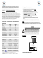
Elektrischer Anschluss
Farbcode: BN=braun WH=weiss GN=grün YE=gelb
16 15 18
BN WH GN YE
a2 b2 a3
L(+) N(-)
NLSW45-4
Sensor
+ F K

The relationship between air velocity and impedance change is non linear. In the lower range of flow velocity, the
change of impedance is very large. In the upper range of flow velocity, identical changes in flow velocity result in
increasingly smaller impedance changes. If the switching point is set, it is important to note what change is to be
monitored because different settings have certain disadvantages.
Note the following requirements:
Small flow change in high flow velocity range: The switching point must be selected very close to the normal flow
reading since flow changes only lead to a very small change in the measured value. Since temperature
compensation takes place with certain delay after the actual temperature change has occurred, this switching point
setting is only suitable for the applications which have slow temperature changes in the medium.
Small flow change in low flow velocity range: The switching point can be selected at a greater interval from the
normal flow reading because a change in flow velocity causes a very large change in the measured value. A
temperature change has no effect on switching behaviour.
Large change in flow rate:
A Yes/NO statement is usually required here (e.g. fan running or fan stationary). You can therefore select a safety
clearance which is so large that neither temperature changes nor turbulence may have an affect on switching
behaviour.
Assembly:
The NLSW45-4 can be mounted on a top-hat rail to DIN EN 50022-35 using bolts or a quick-release clamp.
If the unit is exposed to major vibrations, it is advisable to mount it on a rubber-metal vibration damper.
Commissioning:
Connection and commissioning has to be done by appropriate personnel! Please attend the following steps during
assembling and connecting:
1. Connect the monitoring device as shown in the connection diagram.
2. Connect fitting sensor (F6.1-F6.5). Attention: Incorrect installation leads to malfunctioning or destroying
of both units!
3. Set potentiometers “fein” (fine) and “grob” (coarse) to minimum.
4. Connect the device to power supply. Pay attention to using the correct supply voltage!
5. Switch on the flow generator.
6. Turn potentiometer “grob” (coarse) slowly to maximum until the yellow LED enlightens. To ensure the
correct setup you may to recheck the switching point after two minutes by turning the potentiometer
“fein” (fine) slowly to maximum.
7. To check the flow-monitoring device reduce or turn of the flow. The yellow LED needs to darken and the
relay will drop.
8. Glycol check (below 30% ?)
Attention: Pay attention to the connection diagram and be aware of using the correct voltage!
What to do if the monitoring device does not work properly
Problem
Cause
Sollution
device does not work in any way
no or wrong suplly voltage
check supply voltage and connection
device does not recognice flow
sensor is not installed properly
check the sensor's installation
flow is out of range
change the tube's diameter
device reacts in a different way
sensor is highly polluted
maintain the sensor
device reacts in fast media tepmerature
changes
temperature gradient is out
of range
check the temp. Gradient of your
installation
Mistakes and misprints are not to be excluded. All information „without guarantee“. 08/2018
SEIKOM-Electronic GmbH & Co. KGFortunastr.20D-42489 Wülfrath
Telefon: +49(0) 20 58/20 44 Fax: +49(0) 20 58 / 79 111
E-Mail: info@seikom-electronic.com Internet: http://www.seikom-electronic.de
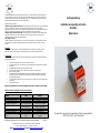
Airflow monitoring
Installation and operating instruction
NLSW45-4
Water and Air
Our products correspond to the requirements of the European guidelines
WEEE 2012/19/EU - RoHS 2011/65/EU

General Information
The monitoring device NLSW45-4 monitors air- and water-flows with the sensors F6.1, F6.2, F6.3, F6.4 and
F6.5 to falling below a step-less settable switching point. The sensor cable is watched for short-circuit and
wire damage. The device provides a potential-free change-over contact.
Measuring principal
A temperature-sensitive resistor is heated according to the calorimetric measuring principle. The temperature-
sensitive resistor is heated by a second resistor. A flow dissipates heat from the measuring resistor, causing the
resistor’s temperature to fall and thus a change of impedance. This temperature change is evaluated. Since both the
velocity and the temperature of the flowing medium affect the dissipated heat, a relationship must be created
between flow and temperature. For this purpose, a second temperature-sensitive resistor is located next to the first
one. The second measuring resistor is not heated and is only used for the temperature measurement.
Airflow > / = switch point Switching output is energised Yellow LED “Airflow“ switch on
Airflow < switch point Switching output isn’t energised Yellow LED “Airflow“ switch off
Technical Data
Type
NLSW45-4
NLSW45-4
Article-No.
75108
74297
Operating Voltage
24V AC/DC
230V AC 50/60Hz
Voltage tolerance
± 5%
± 6%
Over voltage category
||
||
Signal lamp, voltage
Green LED
Green LED
Power consumption
3VA/W
5VA/W
Ambient temperature
-20…+50°C
-20…+50°C
Switching output
Relay, 1 change-over contact
Relay, 1 change-over contact
Relay output
Minimum switching load
250VAC, 8A, 2kVA
10mA / 5V DC
250VAC, 8A, 2kVA
10mA / 5V DC
Signal lamp, airflow
Yellow LED
Yellow LED
Atart up delay
Optional: NLSW45-4Z
Optional: NLSW45-4Z
Signal lamp, start up delay
-
-
Media temperature range
-15…+80°C
-15…+80°C
Switching point adjustment
With potentiometer
With potentiometer
Airflow / waterflow range
0.5-20m/s / 0.05-3m/s
0.5-20m/s / 0.05-3m/s
Measuring probes
F6.1, F6.2, F6.3, F6.4, F6.5
F6.1, F6.2, F6.3, F6.4, F6.5
Electrical connection
10 terminals, 2.5mm²
10 terminals, 2.5mm²
protection category, housing
IP40
IP40
protection category, terminals
IP20
IP20
contamination class
2
2
Housing dimensions
L=120mm, W=45mm, H73mm
L=120mm, W=45mm, H73mm
Certifiction symbols
Type examination TÜV Nord
DIN EN 61010-1:2011-07
Type examination TÜV Nord
DIN EN 61010-1:2011-07
Attention: The glycol-part in the fluid must not be bigger than 30%!
Glycol-parts above 30% may result in failure or destroy the device!
Installation Instruction:
Before setting up the switching point, the device should have been active for at least 2 minutes in normal conditions.
To set up the switching point please attend the following steps:
- The sensors tip should be placed in the duct’s middle and has to be flowed around completely by the
medium.
- The flow in vertical-ducts needs to be upwards.
- To assure maximum reliability the sensor needs a length of the inlet path of 5xD and 3xD of the outlet
path.
- The sensor is to be mounted only with its own hex-head screw.
- The sensor must be connected to the evaluation unit as described in its manual. Incorrect connection
leads to malfunctioning and can destroy both!
- If the sensor’s cable is laid in a conduit with other live cables (motor-, solenoid valve-cables, …) we
recommend shielding it.
- If the length of the cable needs to be changed it needed to be done with a.w.g. 16 (1.5mm²) and must
not be longer than 50m!
Maintenance information:
In order to avoid malfunction the sensor should be maintained in regular distances according to its pollution.
Cleaning the sensor pay attention to following steps:
- Dismantle the sensor.
- Insert the sensor in slightly warm and soaped water carefully for about 10 minutes.
- Carefully rinse off the airflow sensor with lukewarm water.
- Assemble the airflow sensor.
Attention: Do not use screwdrivers or equal to clean the sensor!
Attention!!
Connection and commissioning must be performed by properly authorized and qualified personnel!
Connection to mains supply (L, N) must be made by means of a protected isolating switch with the usual
fuses. As a matter of principle, the General VDE Regulations must be complied with (VDE 0100, VDE 0113,
VDE 0160). If the potential-free contact is connected to an extra-low safety voltage, sufficient insulation
must be provided for the connecting cables up to the terminal, since otherwise the double insulation to the
mains voltage side may be impaired. The current load capacity of the potential-free contact is limited to 10
A. Therefore, the electrical circuit of the potential-free contact must be protected by a 10.3 a fuse.
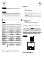
Electrical connection
colours: BN=brown WH=white GN=green YE=yellow
16 15 18
BN WH GN YE
a2 b2 a3
L(+) N(-)
NLSW45-4
Sensor
+ F K
-
 1
1
-
 2
2
-
 3
3
-
 4
4


Seikom Electronic NLSW45-4 Installation and Operating Instruction
- Typ
- Installation and Operating Instruction
in anderen Sprachen
- English: Seikom Electronic NLSW45-4
Andere Dokumente
-
IFM SA3001 Bedienungsanleitung
-
Mastervolt BattMan Pro Benutzerhandbuch
-
Yamaha PSR-EW300 Benutzerhandbuch
-
IFM SN2302 Bedienungsanleitung
-
 S+S Regeltechnik RHEASGARD® KLGFT / KLGFVT RHEASGARD® KLGFT / KLGFVT Bedienungsanleitung
-
Yamaha CLP-S306PE Bedienungsanleitung
-
-
 S+S Regeltechnik RHEASREG® KLSW-W24 Bedienungsanleitung
-
-

