innovative technology SMART Hopper Technical Manual
- Typ
- Technical Manual

Doc: GA00401
Version: 2.0

User Manual SMART Hopper
<< Back to Contents
Copyright © Innovative Technology Ltd 2018 Doc: GA00401
Version: 2.1
Page 1 of 61
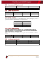
Document Name:
SMART Hopper
Document Version:
2.1
Date of Release:
07/08/2018
TABLE OF CONTENTS
1 DOCUMENT INTRODUCTION .................................................................................................................. 4
1.1 RELATED DOCUMENTS ................................................................................................................................... 4
1.2 MANUAL AMENDMENTS ................................................................................................................................. 4
1.3 COPYRIGHT .................................................................................................................................................. 4
1.4 LIMITED WARRANTY ...................................................................................................................................... 4
1.5 PRODUCT SAFETY INFORMATION ...................................................................................................................... 5
2 PRODUCT INTRODUCTION ...................................................................................................................... 7
2.1 GENERAL DESCRIPTION ................................................................................................................................... 7
2.2 KEY FEATURES .............................................................................................................................................. 7
2.3 TYPICAL APPLICATIONS ................................................................................................................................... 7
2.4 COMPONENT OVERVIEW ................................................................................................................................ 7
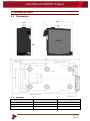
3 TECHNICAL DATA .................................................................................................................................... 8
3.1 DIMENSIONS ................................................................................................................................................ 8
3.2 WEIGHT ...................................................................................................................................................... 8
3.3 ENVIRONMENTAL REQUIREMENTS .................................................................................................................... 9
3.4 POWER REQUIREMENTS ................................................................................................................................. 9
3.4.1 Supply Voltages ............................................................................................................................... 9
3.4.2 Supply Currents ............................................................................................................................... 9
3.4.3 Power Supply Guidance .................................................................................................................. 9
3.5 INTERFACE LOGIC LEVELS ................................................................................................................................ 9
3.6 RELIABILITY DATA ........................................................................................................................................ 10
3.7 MEDIA REQUIREMENTS ................................................................................................................................ 10
4 MECHANICAL INSTALLATION ................................................................................................................ 11
4.1 COMPATIBILITY ........................................................................................................................................... 11
4.1.1 Hardware Compatibility ................................................................................................................ 11
Machine Mounting ............................................................................................................................. 11
Machine Interfacing ............................................................................................................................ 11
Power Supply ...................................................................................................................................... 11
4.1.2 Software Compatibility ................................................................................................................. 12
Interface Protocols .............................................................................................................................. 12
Re-programming ................................................................................................................................. 12
4.2 NOZZLE MOUNTING .................................................................................................................................... 13
4.2.1 Nozzle Fitting ................................................................................................................................ 13
4.2.2 Nozzle Removal ............................................................................................................................. 14
4.3 BASEPLATE MOUNTING ................................................................................................................................ 14
4.3.1 Baseplate Fitting ........................................................................................................................... 14
4.3.2 Baseplate Removal ....................................................................................................................... 15
4.4 LOCK MOUNTING ........................................................................................................................................ 16
4.4.1 Lock Fitting .................................................................................................................................... 16
4.4.2 Lock Removal ................................................................................................................................ 19
4.4.3 Lock Specifications ........................................................................................................................ 20
4.4.4 Lock Cam ....................................................................................................................................... 21
4.5 MACHINE MOUNTING .................................................................................................................................. 22
4.5.1 Machine Mounting ....................................................................................................................... 22
4.5.2 Earth Bonding ............................................................................................................................... 23

User Manual SMART Hopper
<< Back to Contents
Copyright © Innovative Technology Ltd 2018 Doc: GA00401
Version: 2.1
Page 2 of 61
4.5.3 Screw Specifications ...................................................................................................................... 23
5 SOFTWARE INSTALLATION AND CONFIGURATION ................................................................................ 24
5.1 INTRODUCTION ........................................................................................................................................... 24
5.2 SOFTWARE DOWNLOADS .............................................................................................................................. 24
5.3 DRIVERS .................................................................................................................................................... 24
5.4 DATASET/FIRMWARE PROGRAMMING ............................................................................................................ 24
5.4.1 Validator Manager........................................................................................................................ 24
General Description ............................................................................................................................ 24
System Requirements ......................................................................................................................... 24
Hardware Setup .................................................................................................................................. 25
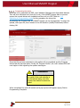
Switching to Programming Mode (SSP) .............................................................................................. 25
Programming the device ..................................................................................................................... 26
5.4.2 Remote Updates ........................................................................................................................... 27
General Description ............................................................................................................................ 27
Hardware Requirements ..................................................................................................................... 27
6 PROTOCOLS AND INTERFACING ............................................................................................................ 28
6.1 INTRODUCTION ........................................................................................................................................... 28
6.2 SSP AND ESSP ........................................................................................................................................... 28
6.2.1 General Description ...................................................................................................................... 28
6.2.2 Pin Assignments ............................................................................................................................ 28
6.2.3 Setup Examples ............................................................................................................................. 31
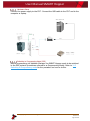
SSP Setup – SMART Hopper Direct USB BENCH TESTING ................................................................... 31
SSP Setup – SMART Hopper with IF17 ................................................................................................ 32
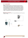
SSP Setup – SMART Hopper and TEBS ................................................................................................ 33
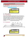
6.3 CC2 ......................................................................................................................................................... 34
6.3.1 General Description ...................................................................................................................... 34
6.3.2 Pin Assignments ............................................................................................................................ 34
6.3.3 ccTalk
®
DES Encryption .................................................................................................................. 36
6.3.4 Setup Example Drawing/s ............................................................................................................. 36
7 ROUTINE MAINTENANCE ...................................................................................................................... 37
7.1 INTRODUCTION ........................................................................................................................................... 37
7.2 RECOMMENDED CLEANING INTERVALS ............................................................................................................ 37
8 FIRST LEVEL SUPPORT ........................................................................................................................... 38
8.1 BEZEL/STATUS LED FLASH CODES .................................................................................................................. 38
8.2 STATUS LED FLASH CODES ............................................................................................................................ 38
9 SECOND LEVEL SUPPORT ...................................................................................................................... 39
9.1 INTRODUCTION ........................................................................................................................................... 39
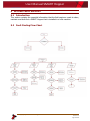
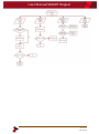
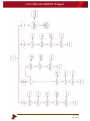
9.2 FAULT FINDING FLOW CHART ........................................................................................................................ 39
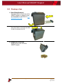
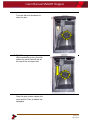
9.3 CLEARING A JAM ......................................................................................................................................... 42
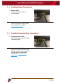
9.4 CHECKING POWER CONNECTIONS ................................................................................................................... 44
9.5 CHECKING COMMUNICATION CONNECTIONS .................................................................................................... 44
9.6 CLEANING THE SMART HOPPER .................................................................................................................... 45
9.7 TIMING CHECK ............................................................................................................................................ 47
9.8 CHECKING PAY-OUT FLAP ............................................................................................................................. 48
10 COMPLIANCES AND APPROVALS .......................................................................................................... 49
10.1 EC DECLARATION OF CONFORMITY ............................................................................................................ 49
11 APPENDIX ............................................................................................................................................. 50
11.1 CABLE DRAWINGS .................................................................................................................................. 50
11.2 LOCK SPECIFICATIONS .............................................................................................................................. 54
11.3 SWITCHING TO PROGRAMMING MODE (SSP) .............................................................................................. 55
11.3.1 Units Pre-Revision 30 ............................................................................................................... 55
11.3.2 Units from Revision 30 ............................................................................................................. 56

User Manual SMART Hopper
<< Back to Contents
Copyright © Innovative Technology Ltd 2018 Doc: GA00401
Version: 2.1
Page 3 of 61
11.4 FREE FALL CASHBOX ADVICE ..................................................................................................................... 56
11.5 CCTALK DES ENCRYPTION – TRUSTED MODE ............................................................................................... 57
11.6 CONFIGURATION BUTTON FUNCTIONS ........................................................................................................ 57
11.7 FILE NAMING CONVENTION ...................................................................................................................... 57
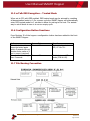
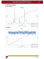
11.8 ENERGY PROFILES ................................................................................................................................... 58
11.8.1 Power up .................................................................................................................................. 58
11.8.2 Idle............................................................................................................................................ 58
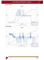
11.8.3 Pay out ..................................................................................................................................... 59
11.8.4 Empty ....................................................................................................................................... 59
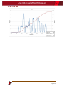
11.8.5 Coin Jam ................................................................................................................................... 60

User Manual SMART Hopper
<< Back to Contents
Copyright © Innovative Technology Ltd 2018 Doc: GA00401
Version: 2.1
Page 4 of 61
1 DOCUMENT INTRODUCTION
1.1 Related Documents
This document should be read together with the following:
For SSP/eSSP:
Protocol Manual – SSP (GA138) : SSP Interface Protocol Specification for integration
SSP Implementation Guide (GA973) : Information for programmers and integrators
For other third-party interface protocols contact support@innovative-
technology.com.
1.2 Manual Amendments
Rev.
Date
Amendment Details
Issued by
2.0
18/05/2018
First Issue
J. Shaw
2.1
07/08/2018
Addition of coin mech socket information, SSP socket update
J. Shaw
1.3 Copyright
This manual set is copyright © Innovative Technology Ltd. 2018. No part of this
publication may be reproduced in any form or by any means used to make any
derivative such as translation, transformation, or adaptation without permission from
Innovative Technology Ltd. The contents of this manual set may be subject to
change without prior notice.
1.4 Limited Warranty
Innovative Technology Ltd warrants each of its hardware products to be free from
defects in workmanship and materials under normal use and service for a period
commencing on the date of purchase from Innovative Technology Ltd or its
Authorized Reseller, and extending for the length of time stipulated by Innovative
Technology Ltd.
A list of Innovative Technology Ltd offices can be found in every section of this
manual set. If the product proves defective within the applicable warranty period,
Innovative Technology Ltd will repair or replace the product. Innovative Technology
Ltd shall have the sole discretion whether to repair or replace, and any replacement
product supplied may be new or reconditioned.
The foregoing warranties and remedies are exclusive and are in lieu of all other
warranties, expressed or implied, either in fact or by operation of law, statutory or
otherwise, including warranties of merchantability and fitness for a particular
purpose.
Innovative Technology Ltd shall not be liable under this warranty if it’s testing and
examination disclose that the alleged defect in the product does not exist or was
caused by the customer's or any third person's misuse, neglect, improper installation
or testing, unauthorized attempts to repair, or any other cause beyond the range of

User Manual SMART Hopper
<< Back to Contents
Copyright © Innovative Technology Ltd 2018 Doc: GA00401
Version: 2.1
Page 5 of 61
the intended use. In no event will Innovative Technology Ltd be liable for any
damages, including loss of profits, cost of cover or other incidental, consequential or
indirect damages arising out the installation, maintenance, use, performance, failure
or interruption of an Innovative Technology Ltd product, however caused.
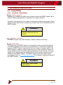
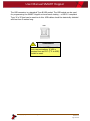
1.5 Product Safety Information
Throughout this user manual key safety points are raised for awareness when using
or maintaining the product.
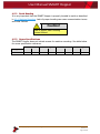
These safety points are highlighted in a box, like this:
Caution!
This is an example text.
This user manual and the information it contains is only applicable to the model
stated on the front cover, and must not be used with any other make or model.

User Manual SMART Hopper
<< Back to Contents
Copyright © Innovative Technology Ltd 2018 Doc: GA00401
Version: 2.1
Page 6 of 61
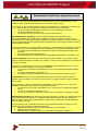
Safety Notice! Read before using this product!
Safety Notice - Warning. Ensure power is removed before allowing access to the inside of this product.
Ensure any static build up is discharged before allowing access to any part of this product or media
contained. Always earth this product/base plate in accordance with the manual.
For use only in or with complete equipment where the acceptability of the combination is determined by
UL LLC. When installed in an end-product, consideration must be given to the following:
• The power supply terminals and/or connectors are: Not investigated for field wiring
• The investigated Pollution Degree is: 2
• The following end-product enclosures are required: Mechanical, Fire
Sicherheitshinweis – Warnung: Es muss sichergestellt werden, dass das Gerät von der
Versorgungsspannung getrennt wird, bevor ein Eingriff in das Innere des Gerätes erfolgt. Es muss
sichergestellt werden, dass jegliche statische Aufladung des Gerätes entladen wird, bevor auf das Gerät
oder auf innerhalb des Gerätes befindliche Objekte zugegriffen wird. Die Erdung des Gerätes muss immer
gemäß Handbuch erfolgen.
Nur für die Verwendung in oder mit kompletter Ausstattung, dessen Eignung und Kombination von der UL
LLC ermittelt wurde. Bei der Installation in einem Endproduckt, muss folgendes berücksichtigt werden:
• Die Spannungsversorgungsklemmen und/oder Verbinder sind: Feldverkabelung wurde nicht
untersucht
• Der untersuchte Verschmutzungsgrad ist: 2
• Folgende Anforderungen an die Gehäuse des Endproduktes sind gefordert: Mechanisch, Feuer
Aviso de seguridad: Asegúrese de que la alimentación está desconectada y de que toda la energía
estática es descargada antes de manipular este producto. Conecte a tierra la chapa base de la manera que
se indica en el manual.
Solo para uso con dispositivos con los cuales la compatibilidad ha sido certificada por UL LLC. Tras su
instalación en producto acabado, tener en cuenta lo siguiente:
• Los conectores y terminales de alimentación son: No se ha investigado/especificado cableado
externo.
• El grado de contaminación determinado es: 2
• Los siguientes manuales/certificados de producto final son requeridos: Mecánico, Fuego
Avis de sécurité : Assurez-vous que l'alimentation est coupée et que toute l'énergie statique est
déchargé avant de manipuler ce produit. Connecter à la terre, la plaque de base à la manière indiquée
dans le manuel.
A utiliser Seulement avec les dispositifs dont la compatibilité a été certifiée par UL LLC. Après son
installation dans le produit fini, prendre en considération ce qui suit:-
• Les connecteurs et les bornes d'alimentation sont : cela n’a pas été étudié/spécifié câblage
externe.
• Le degré de contamination déterminé est: 2
• Les manuels suivants / les certificats du produit final sont nécessaires : mécanique, incendie
Bezpečnostní upozornění. Před manipulací uvnitř tohoto produktu se ujistěte, že je produkt odpojen od
zdroje elektrického napětí. Ujistěte se, že jakýkoliv elektrostatický náboj byl vybit před manipulací s
jakoukoliv částí tohoto produktu nebo obsaženým médiem. Vždy uzemněte tento produkt/základovou
desku v souladu s návodem.
Pouze pro použití v nebo s kompletním vybavením, kde je přijatelnost kombinace určena UL LLC. Při
instalaci v konečném produktu je třeba zvážit nasledující:
• Napájecí svorky a/nebo konektory: Nejsou sledované pro externí kabeláž
• Sledovaný stupeň znečištění je: 2
• Následující krytí konečného produktu jsou požadované: Mechanické, Protipožární

User Manual SMART Hopper
<< Back to Contents
Copyright © Innovative Technology Ltd 2018 Doc: GA00401
Version: 2.1
Page 7 of 61
2 PRODUCT INTRODUCTION
2.1 General Description
The SMART Hopper from Innovative Technology is a state of the art multi-coin
hopper and recycler that eliminates coin starvation. Boasting a market leading mixed
coin capacity, the SMART Hopper removes the need for multiple hoppers,
maximising cash efficiency.
The SMART Hopper reduces the cost of handling coins internally, eliminating the
need for multiple hoppers & sorters. Operating at an industry leading 12 coins per
second the SMART Hopper is a true multi-coin pay-out unit capable of accepting all
coins passed through the coin mechanism.
2.2 Key Features
• State of the art multi coin hopper & recycler
• Technologically advanced
• Lowest cost of ownership
• High security
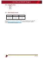
2.3 Typical Applications
• Gaming
• Amusement
• Vending
• Retail & Kiosk
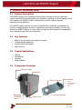
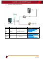
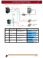
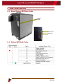
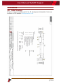
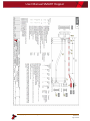
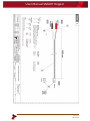
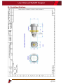
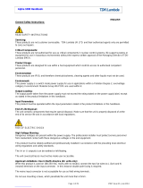
2.4 Component Overview
Baseplate
Unlocking
Latch
6 x Mounting points
Connectors:
• Power
• Communication
• Coin mech
• USB
Exit to Cashbox
Status LEDs
Lid
Pay-out Nozzle


User Manual SMART Hopper
<< Back to Contents
Copyright © Innovative Technology Ltd 2018 Doc: GA00401
Version: 2.1
Page 9 of 61
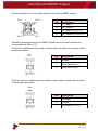
3.3 Environmental Requirements
Environment
Minimum
Maximum
Temperature
+3°C
+50
Humidity
5%
95% Non-condensing
3.4 Power Requirements
3.4.1 Supply Voltages
Supply Voltage
Minimum
Nominal
Maximum
Supply Voltage (V DC)
+ 21.6 V DC
+ 24 V DC
+ 26.4 DC
Supply Ripple Voltage
0 V
0 V
0.25 V @ 100 Hz
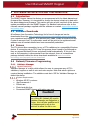
3.4.2 Supply Currents
The supply current required to run the SMART Hopper will vary during the phases of
operation. Below is a table detailing the required current.
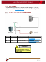
3.4.3 Power Supply Guidance
The SMART Hopper requires a stable 24 V DC / 6.5 A power supply. Check the
power requirements of the host machine and other peripherals to spec a suitable
power environment for the machine setup.
TDK Lambda manufactures suitable power supplies. See the table below for further
details.
Power Supply Unit
Specification
RS Stock Code
Farnell Stock Code
TDK Lambda SWS300-24
+24 V DC / 13.0 A
494-4651
1085928
3.5 Interface Logic Levels
Interface Logic Levels
Logic Low
Logic High
Inputs
0V to +0.5V
+3.7V to +12V
Outputs with 2K2Ω pull-up resistor
+0.6V
Pull-up voltage of host interface
Maximum Current Sink
50mA per Output
Supply Current
Current Draw (A)
Standby
0.2 A
Running
3.0 A
Peak
6.5 A

User Manual SMART Hopper
<< Back to Contents
Copyright © Innovative Technology Ltd 2018 Doc: GA00401
Version: 2.1
Page 10 of 61
3.6 Reliability Data
• MCBF
200,000
• MCBI
50,000
3.7 Media Requirements
Coin
Minimum
Maximum
Diameter
18mm
28.5mm
Thickness
1.6mm
3.2mm
Depending on the currency a different SMART Hopper Hardware type is required.
Contact support@innovative-technology.com for further information. Detailed
information is available on request.

User Manual SMART Hopper
<< Back to Contents
Copyright © Innovative Technology Ltd 2018 Doc: GA00401
Version: 2.1
Page 11 of 61
4 MECHANICAL INSTALLATION
4.1 Compatibility
4.1.1 Hardware Compatibility
Machine Mounting
Assuming the suitable base plate type has been ordered the SMART Hopper can be
used as a fitting replacement for competitor coin hopper solutions.
Innovative Technology Ltd. has a policy of continuous product improvement. Due to
design changes older model or product pay-nozzles may not be compatible with the
SMART Hopper.
Caution!
Only use pay-out nozzle (and
baseplate) delivered with the
product!
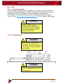
Machine Interfacing
The SMART Hopper may need changes to existing machine harnessing.
Power Supply
It is critical that the SMART Hopper is connected to a power supply being able to
provide the required power at the correct specification. A weak power supply will
cause the SMART Hopper to malfunction like coin rejects or missing credits. If the
SMART Hopper is used as a fitting replacement for an older model or product it is
recommended to check the power supply specifications of the machine. The power
supply of the machine might be designed for the older model or product but not
suitable for the SMART Hopper. The SMART Hopper might have higher power
consumption. Refer to 3.4 Power Requirements for full power requirement details of
the SMART Hopper.
Caution!
A weak power supply causes
malfunctioning!

User Manual SMART Hopper
<< Back to Contents
Copyright © Innovative Technology Ltd 2018 Doc: GA00401
Version: 2.1
Page 12 of 61
4.1.2 Software Compatibility
Interface Protocols
When using the SMART Hopper as a fitting replacement for an older model or
product some events such as credits may be given incorrectly. This is due to
improved firmware routines and faster motors being used. This may cause missing
events such as credits in those host machines where timeouts are defined for the
older model or product. Contact the machine manufacturer for full compatibility of
the SMART Hopper.
Caution!
Timing issues may cause missing
events such as credits!
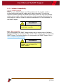
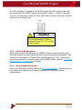
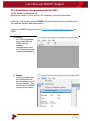
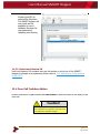
Re-programming
For re-programming the SMART Hopper always use the latest version of Validator
Manager available for download on ITLs website. Older versions may not support the
SMART Hopper. For further details on Re-programming the SMART Hopper refer to
5.4.1.5 Programming the device
Caution!
Older versions of Validator
Manager may not support the
SMART Hopper!

User Manual SMART Hopper
<< Back to Contents
Copyright © Innovative Technology Ltd 2018 Doc: GA00401
Version: 2.1
Page 13 of 61
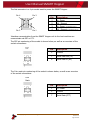
4.2 Nozzle Mounting
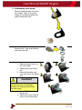
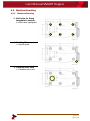
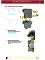
4.2.1 Nozzle Fitting
1. Alignment
Position the pay-out nozzle in line
with the cut outs for the nozzle.
2. First latch
Attach the top clip in to the front
of the SMART Hopper
3. Final attachment
Now place the side clips in to the
corresponding holes and push
until they click in to place

User Manual SMART Hopper
<< Back to Contents
Copyright © Innovative Technology Ltd 2018 Doc: GA00401
Version: 2.1
Page 14 of 61
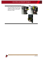
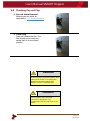
4.2.2 Nozzle Removal
1. Side clips
Pull the low section of the pay-out
nozzle until the 2 side clips
release.
2. Top Clip
Pivoting the nozzle up will unhook
the top clip.
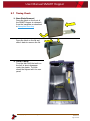
4.3 Baseplate Mounting
4.3.1 Baseplate Fitting
1. Baseplate Fitting
Slide the SMART Hopper on to the
baseplate until it engages the
latch with a click.


User Manual SMART Hopper
<< Back to Contents
Copyright © Innovative Technology Ltd 2018 Doc: GA00401
Version: 2.1
Page 16 of 61
4.4 Lock Mounting
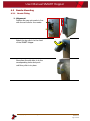
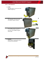
4.4.1 Lock Fitting
1. Latch
Press the latch on the front of the
SMART Hopper up.
2. Pull
With the latch still pressed pull
the SMART Hopper forward.
3. Blanking Plate
The blanking plate is located on
the front of the SMART Hopper
lower right.
4. Screws
Remove the 2 screws and remove
the blanking plate and lock
holder.

User Manual SMART Hopper
<< Back to Contents
Copyright © Innovative Technology Ltd 2018 Doc: GA00401
Version: 2.1
Page 17 of 61
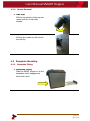
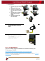
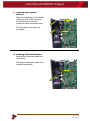
5. Disassembly Lock holder
Remove blanking plate from the
lock holder. Push on the outer
edges of the blanking plate and
push through the hole.
6. Barrel Lock Disassembly
Remove the 2 nuts and direction
cam from the lock.
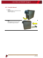
7. Assembly
1. Place the barrel lock in to
the lock holder.
2. Attach barrel lock fixing
nut.
3. Place the direction cam
over the rear of the barrel
lock.
Caution!
Special care should be taken with
the direction cam if positioned
wrong it will change the direction
the lock opens.
4. Place MC00211 on the
barrel lock.
5. Tighten the nylon locking
nut on to the barrel lock.


User Manual SMART Hopper
<< Back to Contents
Copyright © Innovative Technology Ltd 2018 Doc: GA00401
Version: 2.1
Page 19 of 61
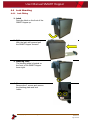
4.4.2 Lock Removal
1. Latch
Press the latch on the front of the
SMART Hopper up.
2. Pull
With the latch still pressed pull
the SMART Hopper forward.
3. Blanking Plate
The blanking plate is located on
the front of the SMART Hopper
lower right.
4. Screws
Remove the 2 screws and remove
the barrel lock assembly.
Seite laden ...
Seite laden ...
Seite laden ...
Seite laden ...
Seite laden ...
Seite laden ...
Seite laden ...
Seite laden ...
Seite laden ...
Seite laden ...
Seite laden ...
Seite laden ...
Seite laden ...
Seite laden ...
Seite laden ...
Seite laden ...
Seite laden ...
Seite laden ...
Seite laden ...
Seite laden ...
Seite laden ...
Seite laden ...
Seite laden ...
Seite laden ...
Seite laden ...
Seite laden ...
Seite laden ...
Seite laden ...
Seite laden ...
Seite laden ...
Seite laden ...
Seite laden ...
Seite laden ...
Seite laden ...
Seite laden ...
Seite laden ...
Seite laden ...
Seite laden ...
Seite laden ...
Seite laden ...
Seite laden ...
-
 1
1
-
 2
2
-
 3
3
-
 4
4
-
 5
5
-
 6
6
-
 7
7
-
 8
8
-
 9
9
-
 10
10
-
 11
11
-
 12
12
-
 13
13
-
 14
14
-
 15
15
-
 16
16
-
 17
17
-
 18
18
-
 19
19
-
 20
20
-
 21
21
-
 22
22
-
 23
23
-
 24
24
-
 25
25
-
 26
26
-
 27
27
-
 28
28
-
 29
29
-
 30
30
-
 31
31
-
 32
32
-
 33
33
-
 34
34
-
 35
35
-
 36
36
-
 37
37
-
 38
38
-
 39
39
-
 40
40
-
 41
41
-
 42
42
-
 43
43
-
 44
44
-
 45
45
-
 46
46
-
 47
47
-
 48
48
-
 49
49
-
 50
50
-
 51
51
-
 52
52
-
 53
53
-
 54
54
-
 55
55
-
 56
56
-
 57
57
-
 58
58
-
 59
59
-
 60
60
-
 61
61


innovative technology SMART Hopper Technical Manual
- Typ
- Technical Manual
in anderen Sprachen
- English: innovative technology SMART Hopper
Verwandte Papiere
Sonstige Unterlagen
-
 TDK-Lambda RFE1600-32 Installationsanleitung
-
Tippmann TMC .50Cal Bedienungsanleitung
-
Acclaim Lighting APS-240-24 Installationsanleitung
-
SCS compact Operating Instructions Manual
-
Sage BCG820 - the Smart Grinder Pro Bedienungsanleitung
-
 StarTech com STNDTBLTMOB Benutzerhandbuch
-
-
 TDK-Lambda Alpha 1000 Benutzerhandbuch
-
Wincor Nixdorf Value Line 3010-5020 Benutzerhandbuch


