innovative technology BV20 Benutzerhandbuch
- Typ
- Benutzerhandbuch

Doc: GA02118
User Manual BV20
Version: 1.0

GA02118 User Manual BV20
<< Back to Contents
Copyright © Innovative Technology Ltd 2018 Doc: GA02118/1 User Manual BV20
Version: 1.0
Page 1 of 60
Document Name:
GA02118 User Manual BV20
Document Version:
1.0
Date of Release:
13-04-2018
TABLE OF CONTENTS
1 DOCUMENT INTRODUCTION .............................................................................................................. 4
1.1 RELATED DOCUMENTS ..................................................................................................................................... 4
1.2 MANUAL AMENDMENTS .................................................................................................................................. 4
1.3 COPYRIGHT .................................................................................................................................................... 4
1.4 LIMITED WARRANTY........................................................................................................................................ 4
1.5 PRODUCT SAFETY INFORMATION ....................................................................................................................... 5
1.6 DISCLAIMER ................................................................................................................................................... 5
2 PRODUCT INTRODUCTION ................................................................................................................. 7
2.1 GENERAL DESCRIPTION .................................................................................................................................... 7
2.2 KEY FEATURES ................................................................................................................................................ 7
2.3 TYPICAL APPLICATIONS .................................................................................................................................... 7
2.4 COMPONENT OVERVIEW .................................................................................................................................. 7
2.4.1 Module Options ................................................................................................................................ 8
2.5 BEZEL OPTIONS .............................................................................................................................................. 8
2.6 CASHBOX OPTIONS ......................................................................................................................................... 8
3 MECHANICAL INSTALLATION ............................................................................................................. 9
3.1 COMPATIBILITY ............................................................................................................................................... 9
3.1.1 Hardware Compatibility ................................................................................................................... 9
3.1.1.1 Machine Mounting ................................................................................................................................. 9
3.1.1.2 Machine Interfacing ................................................................................................................................ 9
3.1.1.3 Power Supply .......................................................................................................................................... 9
3.1.2 Software Compatibility ...................................................................................................................10
3.1.2.1 Interface Protocols ............................................................................................................................... 10
3.1.2.2 Re-programming ................................................................................................................................... 10
3.2 ENTRANCE WIDTH SETTINGS ...........................................................................................................................11
3.2.1 66mm width setting .......................................................................................................................11
3.2.2 72-mm width setting ......................................................................................................................11
3.3 CASHBOX/BASEPLATE MOUNTING ...................................................................................................................12
3.3.1 Cashbox/Baseplate Fitting .............................................................................................................12
3.4 MACHINE MOUNTING ...................................................................................................................................12
3.4.1 BV20 Position .................................................................................................................................12
3.4.2 Earth Bonding .................................................................................................................................13
3.4.3 Screw Specifications .......................................................................................................................13
4 SOFTWARE INSTALLATION AND CONFIGURATION ............................................................................ 14
4.1 INTRODUCTION.............................................................................................................................................14
4.2 SOFTWARE DOWNLOADS ...............................................................................................................................14
4.3 DRIVERS ......................................................................................................................................................14
4.4 DATASET/FIRMWARE PROGRAMMING ..............................................................................................................14
4.4.1 Validator Manager .........................................................................................................................14
4.4.1.1 General Description .............................................................................................................................. 14
4.4.1.2 System Requirements ........................................................................................................................... 14
4.4.1.3 Hardware Setup .................................................................................................................................... 15
4.4.1.4 Switching to Programming Mode (SSP) ................................................................................................ 15
4.4.1.5 Programming the device ...................................................................................................................... 16
4.4.2 DA3 .................................................................................................................................................17
4.4.2.1 General Description .............................................................................................................................. 17
4.4.2.2 System Requirements ........................................................................................................................... 17

GA02118 User Manual BV20
<< Back to Contents
Copyright © Innovative Technology Ltd 2018 Doc: GA02118/1 User Manual BV20
Version: 1.0
Page 2 of 60
4.4.2.3 Re-programming via DA3 ..................................................................................................................... 18
4.4.3 Remote Updates .............................................................................................................................19
4.4.4 Configuration Card .........................................................................................................................20
4.4.4.1 General Description .............................................................................................................................. 20
4.4.4.2 Re-programming via Configuration Card.............................................................................................. 20
5 PROTOCOLS AND INTERFACING ....................................................................................................... 21
5.1 INTRODUCTION.............................................................................................................................................21
5.2 SSP AND ESSP .............................................................................................................................................22
5.2.1 General Description ........................................................................................................................22
5.2.2 Pin Assignments .............................................................................................................................22
5.2.3 Setup Examples ..............................................................................................................................23
5.3 CCTALK
®
......................................................................................................................................................24
5.3.1 General Description ........................................................................................................................24
5.3.2 Pin Assignments .............................................................................................................................24
5.3.3 ccTalk
®
DES Encryption ...................................................................................................................25
5.3.4 Setup Example Drawing/s ..............................................................................................................25
5.4 SIO AND SI2 ................................................................................................................................................26
5.4.1 General Description ........................................................................................................................26
5.4.2 Pinout .............................................................................................................................................29
5.5 MDB .........................................................................................................................................................30
5.5.1 General Description ........................................................................................................................30
5.5.2 Pinout .............................................................................................................................................31
5.5.3 IF5 Interface ...................................................................................................................................32
5.5.4 MDB PSU ........................................................................................................................................32
5.5.5 Setup Example Drawing/s ..............................................................................................................33
5.6 PARALLEL ....................................................................................................................................................35
5.6.1 General Description ........................................................................................................................35
5.6.2 Pinout .............................................................................................................................................35
5.6.3 Inhibit Control .................................................................................................................................35
5.6.4 Escrow Control................................................................................................................................36
5.6.5 Busy Control ...................................................................................................................................36
5.6.6 Low Power Mode ............................................................................................................................36
5.6.7 IF10 Interface .................................................................................................................................36
5.7 BINARY .......................................................................................................................................................37
5.7.1 General Description ........................................................................................................................37
5.7.2 Pinout .............................................................................................................................................37
5.7.3 Inhibit Control .................................................................................................................................38
5.7.4 Escrow Control................................................................................................................................38
5.7.5 Busy Control ...................................................................................................................................38
5.7.6 Low Power Mode ............................................................................................................................38
5.7.7 IF9 Interface ...................................................................................................................................38
5.8 PULSE .........................................................................................................................................................39
5.8.1 General Description ........................................................................................................................39
5.8.2 Pinout .............................................................................................................................................39
5.8.3 Inhibit Control .................................................................................................................................39
5.8.4 Escrow Control................................................................................................................................40
5.8.5 Busy Control ...................................................................................................................................40
5.8.6 Low Power Mode ............................................................................................................................40
5.8.7 Credit Hold Function .......................................................................................................................40
5.8.8 IF15 Interface .................................................................................................................................41
6 ROUTINE MAINTENANCE ................................................................................................................. 42
6.1 INTRODUCTION.............................................................................................................................................42
6.2 RECOMMENDED CLEANING INTERVALS .............................................................................................................42
7 FIRST LEVEL SUPPORT ...................................................................................................................... 43
7.1 BEZEL LED FLASH CODES ...............................................................................................................................43
7.2 CONFIGURATION BUTTON FUNCTIONS ..............................................................................................................43

GA02118 User Manual BV20
<< Back to Contents
Copyright © Innovative Technology Ltd 2018 Doc: GA02118/1 User Manual BV20
Version: 1.0
Page 3 of 60
7.3 CHECKING POWER AND COMMUNICATION CONNECTIONS ....................................................................................43
7.4 PROGRAM CHECK PROCEDURE ........................................................................................................................44
8 SECOND LEVEL SUPPORT ................................................................................................................. 45
8.1 CLEARING A JAM ...........................................................................................................................................45
8.2 CLEANING THE BV20 ....................................................................................................................................46
8.3 CLEARING A CHECKSUM ERROR .......................................................................................................................47
8.4 RE-INITIALISATION OF THE SENSORS ..................................................................................................................48
9 TECHNICAL DATA ............................................................................................................................ 51
9.1 DIMENSIONS ................................................................................................................................................51
9.2 WEIGHT ......................................................................................................................................................51
9.3 ENVIRONMENTAL REQUIREMENTS....................................................................................................................51
9.4 POWER REQUIREMENTS .................................................................................................................................51
9.4.1 Supply Voltages ..............................................................................................................................51
9.4.2 Supply Currents ..............................................................................................................................51
9.4.3 Power Supply Guidance ..................................................................................................................52
9.5 INTERFACE LOGIC LEVELS ................................................................................................................................52
9.6 RELIABILITY DATA .........................................................................................................................................52
9.7 MEDIA REQUIREMENTS..................................................................................................................................52
10 COMPLIANCES AND APPROVALS ...................................................................................................... 53
10.1 EC DECLARATION OF CONFORMITY .............................................................................................................53
11 APPENDIX ....................................................................................................................................... 54
11.1 CABLE DRAWINGS ....................................................................................................................................54
11.2 CONNECTOR SPECIFICATIONS .....................................................................................................................56
11.3 SWITCHING TO PROGRAMMING MODE (SSP) ...............................................................................................56
11.4 FREE FALL CASHBOX ADVICE ......................................................................................................................56
11.5 CCTALK DES ENCRYPTION – TRUSTED MODE ................................................................................................56
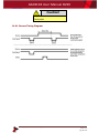
11.6 ESCROW CONTROL ...................................................................................................................................57
11.6.1 Escrow Timing Diagram.............................................................................................................58
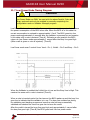
11.7 LOW POWER MODE TIMING DIAGRAM ........................................................................................................59
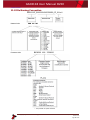
11.8 FILE NAMING CONVENTION .......................................................................................................................60

GA02118 User Manual BV20
<< Back to Contents
Copyright © Innovative Technology Ltd 2018 Doc: GA02118/1 User Manual BV20
Version: 1.0
Page 4 of 60
1 DOCUMENT INTRODUCTION
1.1 Related Documents
This document should be read together with the following:
For SSP/eSSP:
Protocol Manual – SSP (GA138) : SSP Interface Protocol Specification for integration
SSP Implementation Guide (GA973) : Information for programmers and integrators
For other third party interface protocols please contact support@innovative-
technology.com.
1.2 Manual Amendments
Rev.
Date
Amendment Details
Issued by
1.0
22/06/2017
First Issue
MC
1.3 Copyright
This manual set is Copyright © Innovative Technology Ltd. 2016. No part of this
publication may be reproduced in any form or by any means used to make any
derivative such as translation, transformation, or adaptation without permission from
Innovative Technology Ltd. The contents of this manual set may be subject to
change without prior notice.
1.4 Limited Warranty
Innovative Technology Ltd warrants each of its hardware products to be free from
defects in workmanship and materials under normal use and service for a period
commencing on the date of purchase from Innovative Technology Ltd or its
Authorized Reseller, and extending for the length of time stipulated by Innovative
Technology Ltd.
A list of Innovative Technology Ltd offices can be found in every section of this
manual set. If the product proves defective within the applicable warranty period,
Innovative Technology Ltd will repair or replace the product. Innovative Technology
Ltd shall have the sole discretion whether to repair or replace, and any replacement
product supplied may be new or reconditioned.
The foregoing warranties and remedies are exclusive and are in lieu of all other
warranties, expressed or implied, either in fact or by operation of law, statutory or
otherwise, including warranties of merchantability and fitness for a particular
purpose.
Innovative Technology Ltd shall not be liable under this warranty if it’s testing and
examination disclose that the alleged defect in the product does not exist or was
caused by the customer's or any third person's misuse, neglect, improper installation
or testing, unauthorized attempts to repair, or any other cause beyond the range of
the intended use. In no event will Innovative Technology Ltd be liable for any

GA02118 User Manual BV20
<< Back to Contents
Copyright © Innovative Technology Ltd 2018 Doc: GA02118/1 User Manual BV20
Version: 1.0
Page 5 of 60
damages, including loss of profits, cost of cover or other incidental, consequential or
indirect damages arising out the installation, maintenance, use, performance, failure
or interruption of an Innovative Technology Ltd product, however caused.
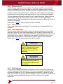
1.5 Product Safety Information
Throughout this user manual, we may draw your attention to key safety points that
you should be aware of when using or maintaining the product.
These safety points will be highlighted in a box, like this:
Caution!
This is an example text.
This user manual and the information it contains is only applicable to the model
stated on the front cover, and must not be used with any other make or model.
1.6 Disclaimer
Innovative Technology Ltd is not responsible for any loss, harm, or damage caused
by the installation and use of this product. This does not affect your local statutory
rights. If in doubt please contact Innovative Technology for details of any changes.
Innovative Technology Ltd has a policy of continual product improvement. As a
result the products supplied may vary from the specification described here.
Innovative Technology Ltd does not accept liability for any errors or omissions
contained within this document. Innovative Technology Ltd shall not incur any
penalties arising out of the adherence to, interpretation of, or reliance on, this
standard.

GA02118 User Manual BV20
<< Back to Contents
Copyright © Innovative Technology Ltd 2018 Doc: GA02118/1 User Manual BV20
Version: 1.0
Page 6 of 60
Safety Notice! Read before using this product!
Safety Notice - Warning. Ensure power is removed before allowing access to the inside of this product.
Ensure any static build up is discharged before allowing access to any part of this product or media
contained. Always earth this product/base plate in accordance with the manual.
For use only in or with complete equipment where the acceptability of the combination is determined by
UL LLC. When installed in an end-product, consideration must be given to the following:
• The power supply terminals and/or connectors are: Not investigated for field wiring
• The investigated Pollution Degree is: 2
• The following end-product enclosures are required: Mechanical, Fire
Sicherheitshinweis – Warnung: Es muss sichergestellt werden, dass das Gerät von der
Versorgungsspannung getrennt wird, bevor ein Eingriff in das Innere des Gerätes erfolgt. Es muss
sichergestellt werden, dass jegliche statische Aufladung des Gerätes entladen wird, bevor auf das Gerät
oder auf innerhalb des Gerätes befindliche Objekte zugegriffen wird. Die Erdung des Gerätes muss immer
gemäß Handbuch erfolgen.
Nur für die Verwendung in oder mit kompletter Ausstattung, dessen Eignung und Kombination von der UL
LLC ermittelt wurde. Bei der Installation in einem Endproduckt, muss folgendes berücksichtigt werden:
• Die Spannungsversorgungsklemmen und/oder Verbinder sind: Feldverkabelung wurde nicht
untersucht
• Der untersuchte Verschmutzungsgrad ist: 2
• Folgende Anforderungen an die Gehäuse des Endproduktes sind gefordert: Mechanisch, Feuer
Aviso de seguridad: Asegúrese de que la alimentación está desconectada y de que toda la energía
estática es descargada antes de manipular este producto. Conecte a tierra la chapa base de la manera que
se indica en el manual.
Solo para uso con dispositivos con los cuales la compatibilidad ha sido certificada por UL LLC. Tras su
instalación en producto acabado, tener en cuenta lo siguiente:
• Los conectores y terminales de alimentación son: No se ha investigado/especificado cableado
externo.
• El grado de contaminación determinado es: 2
• Los siguientes manuales/certificados de producto final son requeridos: Mecánico, Fuego
Avis de sécurité : Assurez-vous que l'alimentation est coupée et que toute l'énergie statique est
déchargé avant de manipuler ce produit. Connecter à la terre, la plaque de base à la manière indiquée
dans le manuel.
A utiliser Seulement avec les dispositifs dont la compatibilité a été certifiée par UL LLC. Après son
installation dans le produit fini, prendre en considération ce qui suit:-
• Les connecteurs et les bornes d'alimentation sont : cela n’a pas été étudié/spécifié câblage
externe.
• Le degré de contamination déterminé est: 2
• Les manuels suivants / les certificats du produit final sont nécessaires : mécanique, incendie
Bezpečnostní upozornění. Před manipulací uvnitř tohoto produktu se ujistěte, že je produkt odpojen od
zdroje elektrického napětí. Ujistěte se, že jakýkoliv elektrostatický náboj byl vybit před manipulací s
jakoukoliv částí tohoto produktu nebo obsaženým médiem. Vždy uzemněte tento produkt/základovou
desku v souladu s návodem.
Pouze pro použití v nebo s kompletním vybavením, kde je přijatelnost kombinace určena UL LLC. Při
instalaci v konečném produktu je třeba zvážit nasledující:
• Napájecí svorky a/nebo konektory: Nejsou sledované pro externí kabeláž
• Sledovaný stupeň znečištění je: 2
• Následující krytí konečného produktu jsou požadované: Mechanické, Protipožární

GA02118 User Manual BV20
<< Back to Contents
Copyright © Innovative Technology Ltd 2018 Doc: GA02118/1 User Manual BV20
Version: 1.0
Page 7 of 60
2 PRODUCT INTRODUCTION
2.1 General Description
The BV20 is a compact, light-weight bill acceptor ideal for amusement and low value
vending applications. Proven field reliability, quick transactions and easy
maintenance make the unit future proof.
Exceptional value, the BV20 allows a bill acceptor to be installed for the same price
as a coin mech.
2.2 Key Features
• Compact bill acceptor
• Simple design
• Exceptional value
• Ideal for amusement, kiddie rides & jukebox applications
2.3 Typical Applications
• Gaming
• Amusement
• Vending
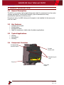
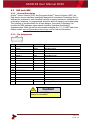
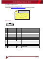
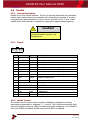
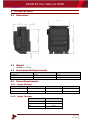
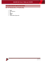
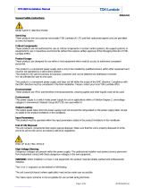
2.4 Component Overview
Lozenge
release catch
Expansion port
clips
Note path
output
Bezel
Configuration
function button

GA02118 User Manual BV20
<< Back to Contents
Copyright © Innovative Technology Ltd 2018 Doc: GA02118/1 User Manual BV20
Version: 1.0
Page 8 of 60
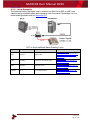
2.4.1 Module Options
ITL Part Number
Description
Details
BV20110VPSU
BV20 110V Power Supply Unit
http://innovative-technology.com/shop/accessories/bv20-
110v-power-supply-unit-detail
2.5 Bezel Options
The BV20 validator is available with either 66mm or 72mm Bezel. Datasets can only
be downloaded to a BV20 with the correct bezel width for the currency. For example
a USD dataset can only be downloaded to a 66mm BV20. A Euro dataset can only be
downloaded to a 72mm BV20.
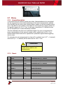
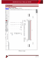
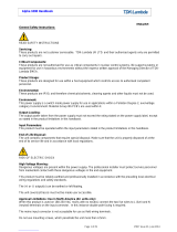
2.6 Cashbox Options
The BV20 validator is designed to have no built-in cashbox. On BV20 installation,
banknotes being validated by BV20 validator must be able to be transported behind
the validator with no obstructions. Banknotes accepted must be able to free fall until
the banknote is not in any contact with BV20 validator body.
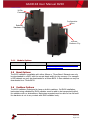
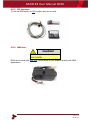
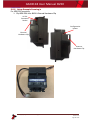
Interface Connector
16-Pin
Connector
External
Hardware Clip
External
Hardware Clip
Configuration
button

GA02118 User Manual BV20
<< Back to Contents
Copyright © Innovative Technology Ltd 2018 Doc: GA02118/1 User Manual BV20
Version: 1.0
Page 9 of 60
3 MECHANICAL INSTALLATION
3.1 Compatibility
3.1.1 Hardware Compatibility
3.1.1.1 Machine Mounting
Assuming the suitable bezel (and cashbox) type has been ordered the BV20 can be
used as fitting replacement for the following products:
• BV20
The BV20 may not be used as fitting replacement for the following products:
• BV50
• BV100
• NV150
• NV9 USB
• NV10 USB
• NV200
Innovative Technology Ltd. has a policy of continuous product improvement. Due to
design changes older model or product bezels (and cashboxes) may not be
compatible with the BV20. However, new product deliveries always include a bezel
(and cashbox) that must be used.
Caution!
Only use bezel (and cashbox)
delivered with the product!
3.1.1.2 Machine Interfacing
By design the BV20 is pin to pin compatible with the suitable fitting replacement
products listed above. No changes to existing machine harnessing are required.
3.1.1.3 Power Supply
It is vital that the BV20 is connected to a power supply being able to provide the
required power environment. A weak power supply causes malfunctioning of the
BV20 such like note rejects or missing credits. If the BV20 is used as a fitting
replacement for an older model or product we recommend to check the power
supply specifications of the machine. The power supply of the machine might be
designed for the older model or product but not suitable for the BV20. The BV20
might have higher power consumption. Refer to 9.4 for full power requirement
details of the BV20.
Caution!
A weak power supply causes
malfunctioning!

GA02118 User Manual BV20
<< Back to Contents
Copyright © Innovative Technology Ltd 2018 Doc: GA02118/1 User Manual BV20
Version: 1.0
Page 10 of 60
3.1.2 Software Compatibility
3.1.2.1 Interface Protocols
When using the BV20 as a fitting replacement for an older model or product some
events such like credits may be given earlier. This is due to improved firmware
routines and faster motors being used. This may cause missing events such like
credits in those host machines where timeouts are defined for the older model or
product. Please contact the machine manufacturer for full compatibility of the BV20.
Caution!
Timing issues may cause missing
events such like credits!
3.1.2.2 Re-programming
For re-programming the BV20 always use the latest version of Validator Manager
available for download on our website. Older versions may not support the BV20.
For further details on Re-programming the BV20 refer to 4.2.
Caution!
Older versions of Validator
Manager may not support the
BV20!

GA02118 User Manual BV20
<< Back to Contents
Copyright © Innovative Technology Ltd 2018 Doc: GA02118/1 User Manual BV20
Version: 1.0
Page 11 of 60
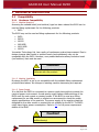
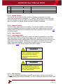
3.2 Entrance Width settings
BV20 has 66mm and 72mm bezel width built-in settings available. The two bezels
width are not interchangeable.
3.2.1 66mm width setting
1. Check imprinted sizing on top
right corner “66mm”
2. Use 66mm dataset file
File can be downloaded from ITL
website/ downloading section
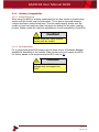
3.2.2 72-mm width setting
1. Check imprinted sizing on top
right corner “72 mm”
2. Use 72mm dataset file
File can be downloaded from ITL
website/ downloading section

GA02118 User Manual BV20
<< Back to Contents
Copyright © Innovative Technology Ltd 2018 Doc: GA02118/1 User Manual BV20
Version: 1.0
Page 12 of 60
3.3 Cashbox/Baseplate Mounting
3.3.1 Cashbox/Baseplate Fitting
BV20 is designed to have no built-in cashboxes. Sufficient space behind BV20 must
be kept free at all time for accepted banknotes and banknote in escrow to free fall
during operation.
3.4 Machine Mounting
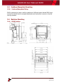
3.4.1 BV20 Position

GA02118 User Manual BV20
<< Back to Contents
Copyright © Innovative Technology Ltd 2018 Doc: GA02118/1 User Manual BV20
Version: 1.0
Page 13 of 60
3.4.2 Earth Bonding
It is very important that the BV20 is properly bonded to earth as described in 3.4.1.
Lack of proper bonding can cause communication issues and other failures.
Caution!
Lack of proper earth bonding
causes failures!
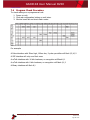
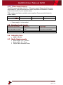
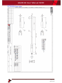
3.4.3 Screw Specifications
The scope of delivery does not include screws for machine mounting. See table
below for screw specification reference.
Head Diameter
Head Height
Bolt Diameter
Bolt Length
Type
Min
Max
Min
Max
Min
Max
Min
Max
Flat Head
7
-
2
-
2.5
4.5
15
42
Pan Head
7
-
2
-
2.5
4.5
15
42

GA02118 User Manual BV20
<< Back to Contents
Copyright © Innovative Technology Ltd 2018 Doc: GA02118/1 User Manual BV20
Version: 1.0
Page 14 of 60
4 SOFTWARE INSTALLATION AND CONFIGURATION
4.1 Introduction
The BV20 leaves the factory pre-programmed with the latest dataset and firmware
files. However, it is important to ensure your device is kept up to date with the latest
dataset and firmware. This section will give you a brief overview of the various
update possibilities with the BV20. For detailed instructions please refer to the
relevant manual package supplied with the software or contact support@innovative-
technology.com.
4.2 Software Downloads
All software from Innovative Technology Ltd is free of charge and can be
downloaded from the website www.innovative-technology.com/support/secure-
download once registered and logged in. If you are not registered, please create an
account via the Create an account form. A confirmation email will be sent to the
registered email address once all contact details have been successfully submitted.
4.3 Drivers
The ITL drivers allow you to connect any of our validators to a compatible Windows
device. If you are connecting via an IF17 then you will not need to follow this
process as they are signed Microsoft Drivers and should install automatically. If this
isn’t the case or your computer is disconnected from the network, there is a
standalone package included within the driver downloads.
4.4 Dataset/Firmware Programming
4.4.1 Validator Manager
4.4.1.1 General Description
Validator Manager is a utility which allows the user to reprogram any of ITL’s
validators, hoppers as well as coin and note recycler. Please note that admin rights
are required during installation. The validator must be in SSP for the Validator
Manager to detect the device.
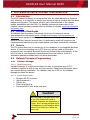
4.4.1.2 System Requirements
• Windows XP SP3 or above
• .Net Framework 4
• 256mb ram
• 50mb hard disk free
• Connected BV20 with active com port
Caution!
We have seen instances where one
of the dll’s (itdata1.dll) used in
Validator Manager are flagged as a
Trojan, this is a false positive and if
this happens you will need to add a
rule to your antivirus to allow the
file to run.

GA02118 User Manual BV20
<< Back to Contents
Copyright © Innovative Technology Ltd 2018 Doc: GA02118/1 User Manual BV20
Version: 1.0
Page 15 of 60
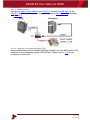
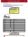
4.4.1.3 Hardware Setup
Connect the power supply cable to the DA2/IF17. Connect the USB cable to the
DA2/IF17 and to your computer or laptop. Connect the CN00174 cable to Validator
and DA2/IF17.
4.4.1.4 Switching to Programming Mode (SSP)
Before programming via the Validator Manager software tool, the BV20 needs to be
switched to its programming mode (SSP interface). Please refer to 11.3 for the
procedure for doing this.

GA02118 User Manual BV20
<< Back to Contents
Copyright © Innovative Technology Ltd 2018 Doc: GA02118/1 User Manual BV20
Version: 1.0
Page 16 of 60
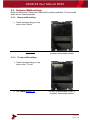
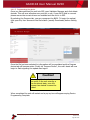
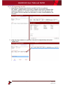
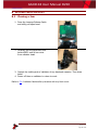
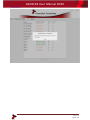
4.4.1.5 Programming the device
Once you have switched the unit into SSP, open Validator Manager and click detect
devices. This will scan all active com ports for a unit, if your BV20 fails to connect
please ensure the correct drivers are installed and the unit is in SSP.
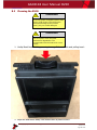
By selecting the Program tab, you can reprogram the BV20. To begin the upload,
click open file, then browse to the file location (usually Downloads) before clicking
OK.
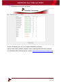
Once the file has been selected its information will be populated and the Program
device tab will become active. Finally hit ‘Program Device’, the unit’s bezel will now
begin to flash signaling the update has begun.
Caution!
Interrupting the download process
can result in the unit entering a
non-functional state, once the
process has started it cannot be
halted.
When completed the unit will restart and a pop up box will appear saying Device
Programming Complete.

GA02118 User Manual BV20
<< Back to Contents
Copyright © Innovative Technology Ltd 2018 Doc: GA02118/1 User Manual BV20
Version: 1.0
Page 17 of 60
4.4.2 DA3
4.4.2.1 General Description
The DA3 is a hand-held validator programming system that enables the user to re-
program ITL banknote validators in the field, without the use of a PC. Dataset and
firmware files for different validator models can be stored on the DA3. Once
programmed the user can update or override existing software as well as test the
functionality of the validator, away from the host machine.
4.4.2.2 System Requirements
• Windows XP SP3 or above
• .Net Framework 4
• 256mb ram
• 50mb hard disk free
• Connected DA3 with active com port
• Data Flash Card (PA01121)
optional

GA02118 User Manual BV20
<< Back to Contents
Copyright © Innovative Technology Ltd 2018 Doc: GA02118/1 User Manual BV20
Version: 1.0
Page 18 of 60
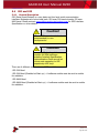
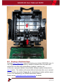
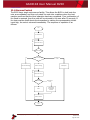
4.4.2.3 Re-programming via DA3
1. Open Device Programming System and add the files you will use.
Set “Match” update mode if you want to update current BV20 dataset after
comparing datasets or “override” update mode, which will reprogram unit
with chosen file and interface not depending on what is downloaded at the
moment:
2. Drag and drop dataset for updating I left part of programming and press
“update files”:

GA02118 User Manual BV20
<< Back to Contents
Copyright © Innovative Technology Ltd 2018 Doc: GA02118/1 User Manual BV20
Version: 1.0
Page 19 of 60
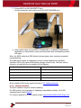
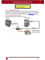
3. Connect BV20 to DA3 VALIDATOT port.
Connect computer/ host machine to DA3 HOST MACHINE port:
4. Using small button choose MATCH DOWNLOAD or OVERRIDE DOWNLOAD
depending on requirements, then press big button and downloading process
will begin.
After, the BV20 restart and DA3 button become green colour meaning successful
reprogramming.
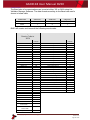
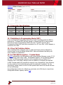
The table below shows an explanation of error codes displayed on the Mode
Indicator LED’s if the center RUN button changes colour to red. The flash code is
shown by a long flash then a number of short flashes:
Cause of faiure (number of short flashes)
Cause of failure
2
No validator connection found
3
No valid download files found
4
Download fail
5
Memory card fail
All the details of DA3 using could be found in ITL Software Manual.
4.4.3 Remote Updates
The BV20 validator supports remote updating.
For SSP protocol, the procedure of updating is described in Section 10 of SSP
Implementation Guide (GA973).
For remote updating in ccTalk, please contact support@innovative-technology.com
Seite wird geladen ...
Seite wird geladen ...
Seite wird geladen ...
Seite wird geladen ...
Seite wird geladen ...
Seite wird geladen ...
Seite wird geladen ...
Seite wird geladen ...
Seite wird geladen ...
Seite wird geladen ...
Seite wird geladen ...
Seite wird geladen ...
Seite wird geladen ...
Seite wird geladen ...
Seite wird geladen ...
Seite wird geladen ...
Seite wird geladen ...
Seite wird geladen ...
Seite wird geladen ...
Seite wird geladen ...
Seite wird geladen ...
Seite wird geladen ...
Seite wird geladen ...
Seite wird geladen ...
Seite wird geladen ...
Seite wird geladen ...
Seite wird geladen ...
Seite wird geladen ...
Seite wird geladen ...
Seite wird geladen ...
Seite wird geladen ...
Seite wird geladen ...
Seite wird geladen ...
Seite wird geladen ...
Seite wird geladen ...
Seite wird geladen ...
Seite wird geladen ...
Seite wird geladen ...
Seite wird geladen ...
Seite wird geladen ...
Seite wird geladen ...
-
 1
1
-
 2
2
-
 3
3
-
 4
4
-
 5
5
-
 6
6
-
 7
7
-
 8
8
-
 9
9
-
 10
10
-
 11
11
-
 12
12
-
 13
13
-
 14
14
-
 15
15
-
 16
16
-
 17
17
-
 18
18
-
 19
19
-
 20
20
-
 21
21
-
 22
22
-
 23
23
-
 24
24
-
 25
25
-
 26
26
-
 27
27
-
 28
28
-
 29
29
-
 30
30
-
 31
31
-
 32
32
-
 33
33
-
 34
34
-
 35
35
-
 36
36
-
 37
37
-
 38
38
-
 39
39
-
 40
40
-
 41
41
-
 42
42
-
 43
43
-
 44
44
-
 45
45
-
 46
46
-
 47
47
-
 48
48
-
 49
49
-
 50
50
-
 51
51
-
 52
52
-
 53
53
-
 54
54
-
 55
55
-
 56
56
-
 57
57
-
 58
58
-
 59
59
-
 60
60
-
 61
61


innovative technology BV20 Benutzerhandbuch
- Typ
- Benutzerhandbuch
in anderen Sprachen
Verwandte Artikel
Andere Dokumente
-
Acclaim Lighting APS-240-24 Installationsanleitung
-
 TDK-Lambda RFE1600-32 Installationsanleitung
-
-
 TDK-Lambda Alpha 1000 Benutzerhandbuch
-
 Printronix Auto ID T6000e Benutzerhandbuch
-
SciCan STATMATIC smart 1 Instructions For Use Manual
-
Wincor Nixdorf iCash 15E Bedienungsanleitung
-
Olympia NC 315 Bedienungsanleitung


