Seite wird geladen ...

Page 1 of 12 IA745-04-01D (a)
R
FE16
00
Inst
allation Manual
ENGLISH
General Safety Instructions:
READ SAFETY INSTRUCTIONS
Servicing:
These products are not customer serviceable TDK-Lambda UK LTD and their authorised agents only are permitted
to carry out repairs.
Critical Components:
These products are not authorised for use as critical components in nuclear control systems, life support systems or
equipment for use in hazardous environments without the express written approval of the Managing Director of TDK-
Lambda EMEA.
Product Usage:
These products are designed for use within a host equipment which restricts access to authorised competent
personnel.
This product is a component power supply and is only to be installed by qualified persons within other equipment and
must be not operated as a stand alone product.
This product is for sale to business to business customers and can be obtained via distribution channels.
It is not intended for sale to end users.
This product is a component power supply and does not fall within the scope of the EMC directive. Compliance with
the EMC directive must be considered in the final installation. Please contact your local TDK-Lambda office.
Environmental:
These products are IPX0, and therefore chemicals/solvents, cleaning agents and other liquids must not be used.
Environment:
This power supply is a switch mode power supply for use in applications within a Pollution Degree 2, overvoltage
category II environment. Material Group IIIb PCB’s are used within it.
Output Loading:
The output power taken from the power supply must not exceed the rating stated on the power supply label, except
as stated in the product limitations in this handbook.
Input Parameters:
This product must be operated within the input parameters stated in the product limitations in this handbook.
End of Life Disposal:
The unit contains components that require special disposal. Make sure that the unit is properly disposed of at the
end of its service life and in accordance with local regulations.
RISK OF ELECTRIC SHOCK
High Voltage Warning:
Dangerous voltages are present within the power supply.The professional installer must protect service personnel
from inadvertent contact with these dangerous voltages in the end equipment.
WARNING: When installed in a Class 1 end equipment, this product must be reliably earthed and professionally
installed.
The (+) or (-) output(s) can be earthed or left floating.
The unit cover(s)/chassis (where applicable) must not be made user accessible.
The mains input connector is not acceptable for use as field wiring terminals.

Page 2 of 12 IA745-04-01D (a)
R
FE16
00
Inst
allation Manual
For encased products, do not use mounting screws, which penetrate the unit more than; See drawings.
Internal fuses protect the unit and must not be replaced by the user. In case of internal defect, the unit must be
returned to TDK-Lambda UK LTD or one of their authorised agents.
A suitable mechanical, electrical and fire enclosure must be provided by the end use equipment for mechanical,
electric shock and fire hazard protection.
Energy Hazards:
The main output of this product is capable of providing hazardous energy (240VA). Final equipment manufacturers
must provide protection to service personnel against inadvertent contact with the output terminals.
The unit cover/chassis, where applicable, is designed to protect skilled personnel from hazards. They must not be
used as part of the external covers of any equipment where they may be accessible to operators, since under full
load conditions, part or parts of the unit chassis may reach temperatures in excess of those considered safe for
operator access.

Page 3 of 12 IA745-04-01D (a)
R
FE16
00
Inst
allation Manual
DEUTSCH
Allgemeine Sicherheitsvorschriften:
LESEN SIE DIE SICHERHEITSVORSCHRIFTEN
Wartung:
Diese Produkte können nicht durch den Kunden gewartet werden. Nur TDK-Lambda UK LTD. und deren
zugelassene Vertriebshändler sind zur Durchführung von Reparaturen berechtigt.
Kritische Komponenten:
Diese Produkte sind nicht für die Verwendung als kritische Komponenten in nuklearen Kontrollsystemen,
Lebenserhaltungssystemen oder Geräten in gefährlichen Umgebungen geeignet, sofern dies nicht ausdrücklich und
in Schriftform durch den Geschäftsführer von TDK-Lambda EMEA genehmigt wurde.
Produktverwendung:
Diese Produkte sind zur Verwendung innerhalb von Host-Anlagen gedacht, die einen auf das Fachpersonal
beschränkten Zugang haben.
Dieses Produkt ist eine Stromversorgungs-Komponente und sie darf nur von qualifiziertem Personal in andere
Geräte eingebaut werden und sie darf NICHT als eigenständiges ("Stand-Alone") Gerät betrieben werden.
Dieses Produkt ist für den Verkauf an Geschäftskunden entwickelt worden und es kann über Distributionskanäle
bezogen werden.
Es ist NICHT für den Verkauf an Endkunden gedacht und konzipiert.
Dieses Produkt ist eine Stromversorgungsbaugruppe und sie fällt NICHT in den Bereich der EMV Direktive.
Die Konformität mit der EMV Richtlinie muss in der finalen Gesamtinstallation betrachtet werden.
Bitte kontaktieren Sie Ihr regionales TDK-Lambda Vertriebsbüro im Falle von Rückfragen.
Umwelt:
Diese Produkte sind IPX0, aus diesem Grund dürfen keine Chemikalien/Lösungsmittel, Reinigungsmittel und andere
Flüssigkeiten verwendet werden.
Umgebung:
Dieses Netzteil ist ein Schaltnetzteil zur Verwendung in einer Umgebung mit einem Verschmutzungsgrad 2,
Überspannungskategorie II. Materialgruppe IIIb mit darin verwendeten PCBs.
Ausgangsstrom:
Der Ausgangsstrom des Netzteiles darf die Leistung, die auf dem Label des Netzteiles vermerkt ist, nur dann
überschreiten, wenn dies in den Produktgrenzen dieses Handbuches ausgezeichnet ist.
Eingangsparameter:
Dieses Produkt muss innerhalb der Eingangsparameter, die in den Produktgrenzen dieses Handbuches angegeben
sind, betrieben werden.
Entsorgung am Ende der Betriebszeit:
Das Gerät enthält Komponenten die unter Sondermüll fallen. Das Gerät muss am Ende der Betriebszeit
ordnungsgemäß und in Übereinstimmung mit den regionalen Bestimmungen entsorgt werden.
GEFAHR DURCH ELEKTRISCHEN SCHLAG
Hochspannungswarnung:
Innerhalb des Netzteiles gibt es gefährliche Spannungen.Der Elektroinstallateur muss das Wartungspersonal vor
versehentlichem Kontakt mit den gefährlichen Spannungen im Endgerät schützen.
WARNUNG! Falls Sie unser Netzgerät in eine Anwendung mit Schutzklasse 1 eingebaut haben, stellen Sie sicher,
dass es fachgerecht installiert und zuverlässig geerdet ist.

Page 4 of 12 IA745-04-01D (a)
R
FE16
00
Inst
allation Manual
Die (+) oder (-) Ausgänge können geerdet werden oder unangeschlossen bleiben.
Die Abdeckung des Gerätes/das Gehäuse darf für den Benutzer nicht zugänglich sein.
Der Haupteingangsanschluss ist nicht für die Verwendung als Feldverdrahtungsanschluss geeignet.
Für ummantelt Produkte, verwenden Sie keine Schrauben, die das Gerät mehr als durchdringen; siehe Zeichnung
Eine interne Sicherung schützt das Gerät und darf durch den Benutzer nicht ausgetauscht werden. Im Fall von
internen Defekten muss das Gerät an TDK-Lambda UK LTD oder einen der autorisierten Vertriebshändler
zurückgeschickt werden.
Ein geeignetes mechanisches, elektrisches und brandgeschütztes Gehäuse muss als Schutz vor der Gefahr von
mechanischen Risiken, Stromschlägen und Brandschutz in dem Endgerät vorgesehen werden.
Gefahren durch elektrische Energie:
Von bestimmten Modulen kann je nach Einstellung der Ausgangsspannung gefährliche elektrische Energie
ausgehen (240 VA). Die Endgerätehersteller müssen einen Schutz für Servicepersonal vor unbeabsichtigtem
Kontakt mit den Ausgangsanschlüssen dieser Module vorsehen. Kann aufgrund der Einstellung gefährliche
elektrische Energie auftreten, dürfen die Modulanschlüsse für den Benutzer nicht zugänglich sein.
Die Geräteabdeckung/das Gehäuse ist so entworfen, dass das Fachpersonal vor Gefahren geschützt wird. Sie
dürfen nicht als Teil der externen Abdeckung für Geräte verwendet werden, die für den Betreiber zugänglich sein
müssen, da Teile oder das gesamte Gerätegehäuse unter voller Auslastung übermäßige Temperaturen erreichen
kann, die für den Zugang des Betreibers nicht mehr als sicher betrachtet werden.

Page 5 of 12 IA745-04-01D (a)
R
FE16
00
Inst
allation Manual
FRANÇAIS
Consignes générales de sécurité:
LIRE LES CONSIGNES DE SECURITE
Entretien:
Ces produits ne peuvent pas être réparés par l’utilisateur. Seuls, TDK-Lambda UK LTD et ses agents agréés sont
autorisés à effectuer des réparations.
Composants critiques:
Ces produits ne doivent pas être utilisés en tant que composants critiques dans des systèmes de commande
nucléaire, dans des systèmes de sauvetage ou dans des équipements utilisés dans des environnements dangereux,
sans l'autorisation écrite expresse du directeur général de TDK-Lambda EMEA.
Utilisation du produit:
Ces produits sont conçus pour être utilisés dans un équipement hôte dont l'accès n'est autorisé qu'aux personnes
compétentes.
Ce produit est une alimentation considérée comme un composant devant être installé par des personnes qualifiées,
dans un autre équipement. Il ne doit pas être utilisé en tant que produit fini.
Ce produit est destiné à la vente entre entreprises et peut être obtenu via des canaux de distribution.
Il n’est pas prévu à la vente pour les particuliers.
Ce produit est une alimentation considérée comme un composant, il ne relève pas du champ d’application de la
directive CEM. Le respect de la directive CEM doit être pris en compte dans l’installation finale. Veuillez contacter
votre bureau TDK-Lambda le plus proche.
Environnement:
Ces produits sont IPX0, et donc on ne doit pas utiliser des produits chimiques/solvants, des produits de nettoyage et
d'autres liquides.
Environnement fonctionnel :
Cette alimentation fonctionne en mode commutation pour utilisation dans des applications fonctionnant dans un
environnement avec Degré de Pollution 2 et catégorie de surtension II. Elle utilise des cartes des circuits imprimés
(PCB) de Groupe IIIb.
Intensité soutirée:
L'intensité soutirée de l'alimentation ne doit pas dépasser l'intensité nominale marquée sur la plaque signalétique,
sauf indications contraires dans les limitations du produit décrit dans ce manuel.
Paramètres d'entrée:
Ce produit doit être utilisé à l'intérieur des paramètres d'entrée indiqués dans les limitations du produit dans ce
manuel.
Elimination en fin de vie:
L'alimentation contient des composants nécessitant des dispositions spéciales pour leur élimination. Vérifiez que
cette alimentation est mise au rebut correctement en fin de vie utile et conformément aux réglementations locales en
vigueur.
RISQUE DE CHOC ELECTRIQUE
Attention-Danger haute tension:
Des tensions dangereuses sont présentes dans l'alimentation. L'installateur doit protéger le personnel d'entretien
contre un contact involontaire avec ces tensions dangereuses dans l'équipement final.
AVERTISSEMENT: Si ce produit est installé dans un équipement final de classe I, il doit être mis à la terre de
manière fiable et installé par un professionnel averti.

Page 6 of 12 IA745-04-01D (a)
R
FE16
00
Inst
allation Manual
Les sorties (+) ou (-) peuvent être raccordées à la terre ou laissées flotttantes.
Le couvercle/châssis de l'alimentation ne doit pas être accessible à l'utilisateur.Le connecteur d'entrée d'alimentation
principale ne doit pas être utilisé comme borne de raccordement.
N'utilisez pas de vis pénétrant dans le module sur une profondeur supérieure à :Voir dessins.
Un fusible interne protège le module et ne doit pas être remplacé par l'utilisateur. En cas de défaut interne, le module
doit être renvoyé à TDK-Lambda UK LTD ou l'un de ses agents agréés.
Une enceinte appropriée doit être prévue par l'utilisateur final pour assurer la protection contre les chocs
mécaniques, les chocs électriques et l'incendie.
Energies dangereuses :
Certains modules peuvent générer une énergie dangereuse (240 VA) selon le réglage de tension de sortie. Le
fabricant de l'équipement final doit assurer la protection des techniciens d'entretien contre un contact involontaire
avec les bornes de sortie de ces modules. Si une telle tension dangereuse risque de se produire, les bornes ou les
connexions du module ne doivent pas être accessibles par l'utilisateur.
Le couvercle et le châssis du module sont conçus pour protéger des personnels expérimentés. Ils ne doivent pas
être utilisés comme couvercles extérieurs d'un équipement, accessible aux opérateurs car en condition de puissance
maximum, des parties du châssis peuvent atteindre des températures considérées comme dangereuses pour
l'opérateur.

Page 7 of 12 IA745-04-01D (a)
R
FE16
00
Inst
allation Manual
ITALIANO
Norme generali di sicurezza:
SI PREGA DI LEGGERE LE NORME DI SICUREZZA
Manutenzione:
Il cliente non può eseguire alcuna manutenzione su questi prodotti. L'esecuzione delle eventuali riparazioni è
consentita solo a TDK-Lambda UK LTD e ai suoi agenti autorizzati.
Componenti critici:
Non si autorizza l'uso di questi prodotti come componenti critici all'interno di sistemi di controllo nucleari, sistemi
necessari alla sopravvivenza o apparecchiature destinate all'impiego in ambienti pericolosi, senza l'esplicita
approvazione scritta dell'Amministratore Delegato di TDK-Lambda EMEA.
Uso dei prodotti:
Questi prodotti sono progettati per l'uso all'interno di un'apparecchiatura ospite che limiti l'accesso al solo personale
competente e autorizzato.
Questo prodotto è da considerarsi come un alimentatore professionale componente e come tale deve essere
installato da personale qualificato all'interno di altre apparecchiature e non può essere utilizzato come prodotto
indipendente.
Questo prodotto non è inteso per la vendita al dettaglio o agli utilizzatori finali.
Questo alimentatore è da considerarsi come un componente e come tale non è assogettato dagli scopi della direttiva
EMC. Conformità alla direttiva EMC deve essere considerata nell'installazione finale di utilizzo. Gli uffici di TDK-
Lambda Sas Succursale Italiana sono a vostra disposizione per ulteriori ragguagli.
Condizioni ambientali:
Questi prodotti sono classificati come IPX0, dunque non devono essere utilizzati sostanze chimiche/solventi, prodotti
per la pulizia o liquidi di altra natura.
Ambiente:
Questo prodotto è un alimentatore a commutazione, destinato all'uso in applicazioni rientranti in ambienti con le
seguenti caratteristiche: Livello inquinamento 2, Categoria sovratensione II. Questo prodotto contiene schede di
circuiti stampati in materiali di Gruppo IIIb.
Carico in uscita:
La potenza in uscita ottenuta dall'alimentatore non deve superare la potenza nominale indicata sulla targhetta
dell'alimentatore, fatto salvo dove indicato nei limiti per i prodotto specificati in questo manuale.
Parametri di alimentazione:
Questo prodotto deve essere utilizzato entro i parametri di alimentazione indicati nei limiti per il prodotto, specificati
in questo manuale.
Smaltimento:
L'unità contiene componenti che richiedono procedure speciali di smaltimento. Accertarsi che l'unità venga smaltita
in modo corretto al termine della vita utile e nel rispetto delle normative locali.
RISCHIO DI SCOSSA ELETTRICA
Avvertimento di alta tensione:
All'interno dell'alimentatore sono presenti tensioni pericolose. Gli installatori professionali devono proteggere il
personale di manutenzione dal rischio di contatto accidentale con queste tensioni pericolose all'interno
dell'apparecchiatura finale.
ATTENZIONE: Se installato in un’attrezzatura di classe I, questo prodotto deve essere collegato a terra in modo
affidabile ed installato in modo professionale.

Page 8 of 12 IA745-04-01D (a)
R
FE16
00
Inst
allation Manual
Le uscite (+) o (-) possono essere messa a terra o lasciate isolate.
I coperchi/il telaio dell'unità non devono essere accessibili da parte dell'utente.
Il connettore dell'alimentazione principale non può essere utilizzato come terminale di collegamento di campo.
Non utilizzare viti che penetrano nell'unità per più di : Vedi disegni
Un fusibile interno protegge l'unità e non deve essere sostituito dall'utente. Nell'eventualità di un difetto interno,
restituire l'unità a TDK-Lambda UK LTD o a uno dei suoi agenti autorizzati.
L'apparecchiatura finale deve includere una recinzione meccanica, elettrica e antincendio per proteggere dai pericoli
di natura meccanica, dalle scosse elettriche e dai pericoli di incendio.
Pericoli energetici:
Alcuni moduli sono in grado di erogare energia pericolosa (240 VA) a seconda della tensione in uscita impostata. I
produttori delle apparecchiature finali sono tenuti a proteggere il personale di manutenzione dal rischio di contatto
accidentale con questi terminali dei moduli di uscita. Se impostati su livelli che non escludono l'erogazione di energia
pericolosa, questi terminali o collegamenti non devono risultare accessibili da parte dell'utente.
Il coperchio/telaio dell'unità è realizzato per proteggere il personale esperto dai pericoli. Non deve essere usato
come parte degli involucri esterni di qualsiasi apparecchiatura, se risulta accessibile da parte degli addetti, poiché è
possibile che in condizioni di pieno carico una o più parti del telaio dell'unità giunga/giungano a temperature superiori
ai limiti considerati sicuri per l'accesso da parte degli addetti.

Page 9 of 12 IA745-04-01D (a)
R
FE16
00
Inst
allation Manual
ESPAÑOL
Instrucciones generales de seguridad:
LEA LAS INSTRUCCIONES DE SEGURIDAD
Servicio:
Estos productos no pueden ser reparados por los clientes. TDK-Lambda UK LTD. y sus agentes autorizados son
los únicos que pueden llevar a cabo las reparaciones.
Componentes fundamentales:
Estos productos no pueden ser utilizados como componentes fundamentales en sistemas de control nuclear,
sistemas de soporte vital o equipos a utilizar en entornos peligrosos sin el consentimiento expreso por escrito del
Director General de TDK-Lambda EMEA.
Uso de los productos:
Estos productos han sido diseñados para ser utilizados en un equipo central que restrinja el acceso al personal
cualificado autorizado.
Este producto es una fuente de alimentación y sólo puede ser instalado por personal cualificado dentro de otros
equipos y no debe ser tratado como un producto independiente. Este producto debe ser vendido entre empresas
profesionales y solo puede obtenerse a través de los canales de distribución .No está destinado para la venta a
usuarios finales
Este producto es una fuente de alimentación y no se ve afectada por la directiva EMC . El cumplimiento de la
directiva EMC se debe considerar en la instalación final. Por favor, póngase en contacto con su oficina local de TDK
– Lambda.
Medioambiental:
Estos productos son IPX0 y, por tanto, no pueden utilizarse sustancias químicas/disolventes, agentes de limpieza ni
otros líquidos.
Medio ambiente:
Esta fuente de alimentación es una fuente de alimentación de modo conmutado a utilizar en aplicaciones dentro de
un entorno con un Grado de contaminación 2 y una Categoría de sobretensión II. En él se utilizan policloruros de
bifenilo del Grupo de materiales IIIb.
Carga de salida:
La potencia de salida tomada de la fuente de alimentación no puede sobrepasar el valor nominal indicado en la
etiqueta de la fuente de alimentación, excepto en los casos indicados en las limitaciones del producto en este
manual.
Parámetros de entrada:
Este producto debe ser utilizado dentro de los parámetros de entrada indicados en las limitaciones del producto en
este manual.
Desecho de la unidad:
La unidad contiene componentes que deben ser desechados de una manera especial. Asegúrese de desechar
correctamente la unidad al final de su vida útil y conforme a las normas locales vigentes.
PELIGRO DE DESCARGAS ELÉCTRICAS
Advertencia de alta tensión:
En esta fuente de alimentación hay tensiones peligrosas. El instalador profesional debe proteger al personal de
servicio contra cualquier contacto accidental con estas tensiones peligrosas en el equipo final.
ADVERTENCIA: La instalación de este producto en un equipo de clase I la deben llevar a cabo profesionales y el
producto debe estar conectado a tierra.

Page 10 of 12 IA745-04-01D (a)
R
FE16
00
Inst
allation Manual
La salida o salidas (+) o (-) pueden conectarse a tierra o se las puede dejar flotando.
Debe impedirse el acceso de los usuarios a la cubierta o cubiertas y al chasis de la unidad.
El conector de entrada de la red no es apto para ser utilizado a modo de bornes de cableado de campo.
No utilice tornillos de montaje susceptibles de penetrar en la unidad más de: Ver dibujos.
Un fusible interno protege la unidad y este no debe ser nunca reemplazado por el usuario. En caso de existir algún
defecto interno, la unidad debe ser enviada a TDK-Lambda UK LTD o a uno de sus agentes autorizados.
El equipo de uso final debe constituir un recinto de protección mecánica, eléctrica y contra incendios de protección
mecánica, contra descargas eléctricas y contra el peligro de incendios.
Peligros de energía:
Algunos módulos pueden generar energía peligrosa (240VA) dependiendo de la configuración de la tensión de
salida. Los fabricantes de equipos finales deben proteger al personal de servicio contra un contacto accidental con
estos bornes de salida de los módulos. Si se configura de modo que pueda generarse energía peligrosa, hay que
evitar que el usuario pueda acceder a los bornes o conexiones del módulo.
La cubierta/chasis de la unidad ha sido diseñada para que proteja a las personas cualificadas de los peligros. No
deben ser utilizadas como parte de las cubiertas externas de cualquier equipo al que pueden acceder los operarios,
ya que bajo unas condiciones de carga completa, la pieza o piezas del chasis de la unidad pueden alcanzar
temperaturas superiores a las consideradas seguras para el acceso de los operarios.

Page 11 of 12 IA745-04-01D (a)
R
FE16
00
Inst
allation Manual
PORTUGUÊS
Instruções gerais de segurança:
LEIA AS INSTRUÇÕES DE SEGURANÇA
Manutenção:
Estes produtos não são podem ser submetidos a manutenção por parte do cliente. Apenas a TDK-Lambda UK LTD
e os seus agentes autorizados têm permissão para realizar reparações.
Componentes essenciais:
Não é autorizada a utilização destes produtos como componentes essenciais de sistemas de controlo nuclear,
sistemas de suporte de vida ou equipamento para utilização em ambientes perigosos sem a expressa autorização
por escrito do Director-Geral da TDK-Lambda EMEA.
Utilização do produto:
Estes produtos foram concebidos para utilização dentro de um equipamento de alojamento que apenas permita o
acesso a pessoal qualificado autorizado.
Este produto é uma alimentaçao considerado com um componente para ser instalado por pessoas qualificadas, em
outros equipamentos. Não deve ser usado como um produto acabado.
Este produto é destinado para venda entre as empresas e pode ser obtido através de canais de distribuição.
Não se destina à venda aos particulares.
Este produto é uma alimentaçao considerado com um componente, não é dentro do appliquation âmbito da directiva
CEM.
Conformidade com a directiva CEM devem ser considerados na instalação final.
Entre em contacto com seu escritório TDK-Lambda mais próximo.
Ambiental:
Estes produtos são IPX0 e, como tal, não se devem utilizar químicos/solventes, agentes de limpeza e outros
líquidos.
Ambiente:
Esta fonte de alimentação é uma fonte de alimentação do modo de comutação para utilização em aplicações com
um Nível de Poluição 2 e ambientes da categoria de sobretensão II. São utilizadas placas de circuitos impressos do
grupo de materiais IIIb.
Carga de saída:
A potência de saída extraída da fonte de alimentação não deve exceder a classificação assinalada na etiqueta da
fonte de alimentação, excepto quando indicado nas limitações do produto neste guia.
Parâmetros de entrada:
Este produto deve ser utilizado dentro dos parâmetros de entrada indicados nas limitações do produto neste guia.
Eliminação no fim de vida:
A unidade contém componentes que necessitam de procedimentos especiais de eliminação. Certifique-se de que a
unidade é devidamente eliminada no fim da sua vida útil e que tal é feito em conformidade com os regulamentos
locais.
RISCO DE CHOQUE ELÉCTRICO
Aviso de alta tensão:
Estão presentes tensões perigosas dentro da fonte de alimentação. O profissional que realizar a instalação deve
proteger o pessoal de assistência contra contactos inadvertidos com estas tensões perigosas do equipamento final.
AVISO: Quando instalado num equipamento de Classe I, este produto deve ser ligado à terra de forma fiável e
instalado por um profissional.
.

Page 12 of 12 IA745-04-01D (a)
R
FE16
00
Inst
allation Manual
As saídas (+) e (-) podem ser ligadas à terra ou deixadas soltas.
O chassis/cobertura(s) da unidade não deve estar acessível ao utilizador.
O conector de entrada de alimentação não deve ser utilizado como terminal de cablagens no local.
Não utilize parafusos de montagem, uma vez que estes penetrarão na unidade em mais do que: Veja os desenhos
Existe um fusível interno que protege a unidade e que não deve ser substituído pelo utilizador. Em caso de defeito
interno, a unidade deve ser devolvida à TDK-Lambda UK LTD ou a um dos seus agentes autorizados.
O equipamento de utilização final deve fornecer um bastidor com protecção mecânica, eléctrica e contra incêndios
adequada.
Perigos de energia:
Alguns módulos tem a capacidade de fornecer energia perigosa (240 VA), de acordo com a configuração da tensão
de saída. O equipamento final do fabricante deve garantir que o pessoal de assistência está protegido contra
contactos inadvertidos com estes terminais de saída do módulo. Se essa energia perigosa for produzida, as
ligações e os terminais do módulo não devem ser acessíveis pelos utilizadores.
O chassis/cobertura da unidade está concebido de forma a proteger o pessoal especializado de perigos. Não devem
ser utilizados como parte das coberturas externas de qualquer equipamento em que possam estar acessíveis aos
operadores, uma vez que em condições de carga máxima, algumas peças do chassis da unidade podem atingir
temperaturas superiores às consideradas seguras para o acesso do operador.
TDK-Lambda UK Ltd
Kingsley Avenue, Ilfracombe
Devon, EX34 8ES
Telephone - Sales and Service +44 (0)1271 856666
Head Office and Works +44 (0)1271 856600
Facsimile +44 (0)1271 864894
WEBSITE: www.uk.tdk-lambda.com

IA745-04-01 Rev. D
RFE1600 & RFE1600/S (PMBUS) SERIES INSTRUCTION MANUAL
CHAPTER 1: RFE1600 & RFE1600/S (PMBus) SERIES SPECIFICATIONS......................................1
1.1
RFE1600 rated output Current and Voltage versus Line Voltage. ............................. 3
1.2
RFE1600 Output Power vs. Temp derating. ............................................................... 4
1.3
RFE1600 Outline Drawing .......................................................................................... 5
1.4
Rear Panel IN/OUT Connector Pins Function Description
..................................... 6
CHAPTER 2: SAFETY APPROVALS ...........................................................................................7
2.1
Safety Instructions ...................................................................................................... 7
CHAPTER 3: SINGLE UNIT OPERATION ................................................................................. 10
3.1
Rear Panel Indicators ............................................................................................... 10
3.2
Single unit operation ................................................................................................ 11
3.2.1 Basic configuration (Local Sense) ............................................................... 11
3.2.2 Basic configuration (Remote Sense) ........................................................... 11
3.2.3 ON/OFF Control by Enable .......................................................................... 12
3.2.4 Output Voltage Programming by Built-in Potentiometer .......................... 12
3.2.5 Output Voltage Programming by PMBus (Optional) .................................. 12
3.2.6 Output Voltage Programming by External Voltage .................................... 13
3.2.7 Current Programming by PMBus (Optional) ............................................... 13
3.2.8 Over Current Programming by External Voltage ........................................ 14
3.2.9 SUPERVISORY Signals (Typical Connection) ................................................ 14
CHAPTER 4: POWER SUPPLIES CONNECTION ....................................................................... 15
4.1
Parallel Operation .................................................................................................... 15
4.2
Series Operation ....................................................................................................... 16
CHAPTER 5: PMBus INTERFACE OPTION .............................................................................. 17
5.1
RFE1600/S Series I²C Specification ........................................................................... 17
5.1.1 PMBus Interface Option ............................................................................. 18
5.1.2 RFE1600 May Have Optional Power Management Bus Hardware ............. 18
5.1.3 Addressing (A3, A2, A1, A0 Inputs) ............................................................. 18
5.1.4 Serial Clock .................................................................................................. 18
5.1.5 Serial Data ................................................................................................... 18
5.1.6 SMB Alert .................................................................................................... 19
5.1.7 PMBus Typical Connection ......................................................................... 19
5.2
PMBus Command Set ............................................................................................... 20
5.2.1 Read Status ................................................................................................. 20
5.2.2 Clear Faults ................................................................................................. 20
5.2.3 Operation (ON/OFF) ................................................................................... 20
5.2.4 Commands to Read Inventory Details ........................................................ 20
5.3
Programming and Monitoring Functions ................................................................. 21
5.3.1 Monitoring Output Voltage (READ_VOUT) ................................................. 21
5.3.2 Monitoring Output Current (READ_IOUT) .................................................. 22
5.3.3 Monitoring Supply Temperature (READ_TEMPERATURE_1) ..................... 22
5.3.4 Programming Output Voltage (VOUT_COMMAND) ................................... 22
5.3.5 Programmable Maximum Output Voltage (VOUT_MAX) ........................... 23
5.3.6 Programming Output Current Limit............................................................ 23
5.3.7 Enabling / Disabling Monitoring Filter ........................................................ 23

1
CHAPTER 1: RFE1600 & RFE1600/S (PMBUS) SERIES SPECIFICATIONS
RFE1600 SERIES SPECIFICATIONS:
RFE1600-12
RFE1600-12/S
RFE1600-24
RFE1600-24/S
RFE1600-32
RFE1600-32/S
RFE1600-48
RFE1600-48/S
1
Rated output voltage
V
12
24
32
48
2
Output voltage set point
V
12+/-1%
24+/-1%
32+/-1%
48+/-1%
3
Output voltage range
V
9.6~13.2
19.2~29.0
25.6~38.4
38.4~58
4
Rated Output Current at Vin ≥ 170Vac (*1)
A
133
67
47
33
5
Rated Output Current at 100 ≤ Vin ≤ 132Vac (*1)
A
92
46
34.5
23
6
Rated Output Current at 85V ≤Vin < 100Vac (*1)
A
Linear derating 0.6% per 1Vac from output current at 100Vac.
7
Rated output power Vin ≥ 170Vac
W
1596
1608
1504
1584
8
Rated output power 100 ≤ Vin ≤ 132Vac
W
1104
1104
1104
1104
9
Rated output power 85Vac ≤ Vin < 100Vac
W
Linear derating 0.6% per 1Vac from output power at 100Vac.
10
Input voltage / frequency range (*2)
---
85~265Vac continuous, 47~63Hz, Single phase.
11
Maximum input current (at 115/230Vac)
A
11.6/8.1.
12
Power Factor (Typ.) (at 115/230Vac)
---
>0.99/0.98 at maximum output power.
13
Efficiency at 75% rated load (Typ.) (*3)
%
87/90
88/90
88/90
89/92
14
Efficiency at 100% rated load (Typ.) (*3)
%
87/90
87/90
87/90
88/91
15
Inrush current (*4)
A
Less than 35.
16
Hold-up time
mS
≥ 10mS typical at 115/230Vac input, rated output voltage and less than 80% of rated load.
17
Maximum line regulation (*5)
%
0.25
18
Max load regulation (*6)
%
0.50
19
Output Ripple and noise P-P (*7)
0~+70°C
mV
240
240
350
480
-10~0°C
mV
360
360
580
780
20
Temperature stability
---
0.05% of rated Vout for 8hrs after 30min warm-up. Constant line, load and temp.
21
Temperature coefficient of output voltage
PPM/°C
+/-200.
22
Remote sensing (*8)
---
Possible. Refer to Instruction Manual.
23
Parallel operation (*9)
---
Possible. Single wire current share, 5% accuracy of rated Iout, up to 10 units of the same voltage rating.
24
Series operation
---
Possible (with external diodes), 2 units. Refer to Instruction Manual.
25
Over current protection
85V ≤ Vin < 132Vac
---
Minimum 105% of rated output current.
170V ≤ Vin < 265Vac
---
105~120% of rated output current.
26
Over voltage protection (*10)
V
Tracking OVP, range: 1.1xVout, accuracy: +/-3%, refer to Instruction Manual.
27
Over temperature protection
---
Inverter shut down method, automatic recovery.
28
Remote On/Off control
---
By electrical signal or dry contact. Refer to Instruction Manual.
29
"DC OK" signal (*13)
---
Tracking, On when Vout>90+/-5% of output voltage setting.
30
Over-Temperature warning (*13)
---
Refer to Instruction Manual.
31
"AC FAIL" signal (*13)
---
On when 85Vac<Vin<270Vac.
32
Auxiliary power supply output (*11)
---
11.2~12.5V, 0.5A. 240mVp-p ripple and noise.
33
Vout programming by external voltage
---
By 0~5V, equal to Vout min ~ Vout max. Refer to Instruction Manual.
34
Vout programming by built-in potentiometer
---
By 1Kohm potentiometer. Refer to Instruction Manual.
35
OCP programming by external voltage
---
By 0~5V. Refer to Instruction Manual.
36
Rear panel indicators
---
DC OK. Refer to Instruction Manual.
37
I²C Interface
---
Optional, PMBus compatible. Refer to Instruction Manual.
38
Operating temperature (*15)
---
-10~+50°C: 100% load.
+50°C to +60°C Derate 2%/°C of load
+60°C to +70°C Derate 2.5%/°C of load
39
Storage temperature
---
-30~85°C.
40
Operating humidity
---
10~90% RH, no condensation.
41
Storage humidity
---
10~95% RH, no condensation.
42
Cooling
---
By internal Fans. Variable speed control based on ambient temp and power level.
43
Vibration
---
At no operation, 10 - 50Hz (Sweep for 1min.) 2G Constant X, Y, Z 1h each.
44
Shock
---
Less than 20G.
45
Conducted emission (*14)
---
Built to meet EN55032 Class B, FCC part 15 Class-B, VCCI Class-B.
46
Radiated emission (*14)
---
Built to meet EN55032 Class A, FCC part 15 Class-A, VCCI Class-A.
47
Immunity
---
Built to meet IEC61000-4-2 (Level 2,3),
-3 (Level 2), -4 (Level 2), -5 (Level 3,4), -6 (Level 2), -8 (Level 4), -11.
48
Applicable safety standards
---
UL60950-1, EN60950-1.
49
Withstand voltage
Input-Output:
---
3000Vrms, 1min.
Input-Ground:
2000Vrms, 1min.
Output - Ground:
500Vrms, 1min.
500Vrms, 1min.
500Vrms, 1min.
2250Vdc, 1min.
50
Insulation resistance
---
More than 100Mohm at 25°C and 70% RH. Output-Ground: 500Vdc.
51
Leakage current (*12)
mA
Less Than 0.75/1.5 at 115/230Vac range.
52
Weight (Typ.)
Kg
Max. 1.7.
53
Size (W*H*D)
---
85x41x320mm. Refer to Outline Drawing.

2
Notes:
*1 Refer to (Paragraph 1.1).
*2 For cases where conformance to various safety standards (UL, EN etc.) is required, input voltage to be
described as 100-240Vac (50/60Hz).
*3 At 115/230Vac, 25˚C ambient temperature.
*4 Not applicable for the noise filter inrush current less than 0.2mS.
*5 From 85~132Vac or 170~265Vac, constant load.
*6 From No-load to Rated load, constant input voltage. Measured at the sensing point in Remote sense.
*7 Measured with JEITA-RC9131A 1:1 probe with 2x270uF electrolytic capacitors and 1uF film capacitor on the
output, 20MHz B.W.
*8 Voltage drop on load wires: RFE1600-12: 0.25V/wire; RFE1600-24: 0.5V/wire; RFE1600-32: 0.75V/wire;
RFE1600-48: 1V/wire.
*9 Accuracy applicable for load current > 50% of rated output current. Derate maximum output power by 5%.
*10 Inverter shut down method. Reset by AC voltage recycle or by On/Off control.
*11 Measured with JEITA-RC9131A 1:1 probe with 470uF electrolytic capacitor and 0.1uF film capacitor on the
output, 20MHz B.W.
*12 Measured according to UL, EN method at 60Hz, 25˚C ambient temperature.
*13 Open collector signal. Maximum sink current: 10mA, maximum voltage 15V.
*14 RFE1600 series considered as professional equipment and not intended for sale to general public.
*15 Refer to Output Power vs. temp derating (Paragraph 1.2).

3
76A
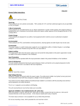
1.1
RFE1600 rated output Current and Voltage versus Line Voltage.
Figure 1–1: RFE1600-48; 48/S
Figure 1–2: RFE1600-32; 32/S
Figure 1–3: RFE1600-24; 24/S
Figure 1–4: RFE1600-12; 12/S
17A
21A
23A
28A
33A
265Vac
170Vac
132Vac
100Vac
85Vac
26A
31.5A
34.5A
39A
47A
265Vac
170Vac
132Vac
100Vac
85Vac
34A
42.5A
46A
56A
67A
265Vac
170Vac
132Vac
100Vac
85Vac
85A
87.5A
92A
121A
133A
265Vac
170Vac
132Vac
100Vac
85Vac
1584W Max
1104W Max
1000W Max
Iout
Vin
1504W Max
1104W Max
1000W Max
Iout
Vin
1608W Max
1104W Max
1000W Max
Iout
Vin
1596W Max
1104W Max
1000W Max
Iout
Vin
38.4~48V
58V
25.6~32V
38.4V
19.2~24V
29V
9.6~12V
13.2V

4
1.2
RFE1600 Output Power vs. Temp derating.
Figure 1–5: Output Power at temp -10~50°C.
Figure 1–6: Output Power derating at temp 60°C.
Figure 1–7: Output Power derating at temp 70°C.
1600W
265Vac
170Vac
132Vac
100Vac
85Vac
1500W
265Vac
170Vac
132Vac
100Vac
85Vac
1280W
265Vac
170Vac
132Vac
100Vac
85Vac
1200W
265Vac
170Vac
132Vac
100Vac
85Vac
880W
265Vac
170Vac
132Vac
100Vac
85Vac
825W
265Vac
170Vac
132Vac
100Vac
85Vac
550W
550W
RFE1600-32V
RFE1600-12, 24, 48V
RFE1600-12, 24, 48V
RFE1600-32V
RFE1600-32V
RFE1600-12, 24, 48V
1104W
1050W
1000W
1104W
1050W
1000W
Pout
Pout
Pout
Pout
Pout
Pout
880W
840W
800W
880W
840W
800W
600W
575W
600W
575W
Vin
Vin
Vin
Vin
Vin
Vin


6
1.4
Rear Panel IN/OUT Connector Pins Function Description
J1 – Main Connector
Pin #
Function
Description
Referenced to
J1-1, J1-14
-SENSE
Negative sense.
The -SENSE signal should be connected to -V on Power Supply or Load side.
-SENSE
J1-2
+SENSE
Positive sense.
The +SENSE signal should be connected to +V on Power Supply or Load side.
+SENSE
J1-3
VOLTAGE
PROGRAMMING
Input 0~5V. Provides Vout programming by Voltage.
Refer to Section 3.2.4, Section 3.2.5 and Section 3.2.6.
-SENSE
J1-4
CURRENT
PROGRAMMING
Input 0~5V. Provides Current programming by Voltage.
Refer to Section 3.2.7 and Section 3.2.8.
-SENSE
J1-5
V_REF
Variable when Voltage/Current programming is done with PMBus option. Refer
to Instruction Manual
-SENSE
J1-6
TEMP ALARM
TEMP ALARM signal. LOW when the internal temperature is within safe limit;
HIGH approx. 10°C below Thermal shut down. Open collector type (15V, 10mA).
SIGNAL RETURN
J1-7
DC OK
DC OK signal. LOW when the output voltage is higher than 85~95% of Vout set.
Open collector type (15V, 10mA).
SIGNAL RETURN
J1-8
ENABLE
Turns ON the main output by electrical signal or dry contact (0~0.6v or short).
SIGNAL RETURN
J1-9, J1-17
SIGNAL RETURN
Return for the following control signals: ENABLE supervisory signals TEMP
ALARM, AC FAIL, AUX and PMBus signals: SCL, SDA, SMB ALERT,
SIGNAL RETURN and mentioned signals are isolated from the output terminals
and
-SENSE.
J1-10
Local -SENSE
Negative Output Voltage (Can't supply load current)
-V
J1-11
Local +SENSE
Positive Output Voltage (Can't supply load current)
+V
J1-12
TRIMMER
Refer to Section 3.2.4.
-SENSE
J1-13
+5V
5V fix output for standard option unit.
-SENSE
J1-15
AC FAIL
AC FAIL Signal; LOW when the input voltage is 85Vac<Vin<270Vac;
HIGH when the input voltage is Vin<85Vac or Vin>270Vac.
Open collector type (15V, 10mA).
J1-15
J1-16
CURRENT SHARE
Current sharing signal should be connected when Power Supplies are connected
in parallel to allow accurate current share between units.
-SENSE
J1-18
+12V AUX OUT
11.2~12.5V Auxiliary Voltage Output. Maximum load current is 0.5A.
This output has a built in O-Ring diode.
Not affected by the ENABLE signal or any other fault.
SIGNAL RETURN
J2 - Optional PMBus interface
J2-1, J2-2,
J2-3
A0, A1, A1
(optional PMBus)
PMBus Address lines. Refer to the PMBus interface description RFE
Instruction Manual Section 5.1.3.
-SENSE
J2-4
Remote (-) SENSE
Negative sense.
-SENSE
J2-5
SMB ALERT
(optional PMBus)
PMBus INTERRUPT signal.
Refer to the PMBus interface description RFE Instruction Manual.
SIGNAL RETURN
J2-6
SDA
(optional PMBus)
Serial Data signal.
Refer to the PMBus interface description RFE Instruction Manual.
SIGNAL RETURN
J2-7
SCL
(optional PMBus)
Serial Clock signal.
Refer to the PMBus interface description RFE Instruction Manual.
SIGNAL RETURN
J2-8
SIGNAL RETURN
Return for the following control signals: ENABLE supervisory signals TEMP
ALARM, AC FAIL, AUX and PMBus signals: SCL, SDA, SMB ALERT,
SIGNAL RETURN and mentioned signals are isolated from the output terminals
and -SENSE.
SIGNAL RETURN
TB
TB-1
AC LINE
AC LINE. Refer to Section 2.1 for Safety Instructions.
TB-2
AC NEUTRAL
AC NEUTRAL. Refer to Section 2.1 for Safety Instructions.
TB-3
PROTECTIVE GROUND
AC GROUND. Refer to Section 2.1 for Safety Instructions.
Table 1-1:
Rear panel IN/OUT pins
Figure 1–8: IN/OUTPUT CONNECTORS

7
CHAPTER 2:
SAFETY APPROVALS
UL 60950-1 and CSA22.2 No.60950-1 - UL Recognized. C-UL for Canada.
IEC 60950-1 - CB Report and Certificate.
EN 60950-1 - CE mark.
Marking by the CE Symbol indicates compliance to the Low Voltage Directive of the European Union.
A “Declaration of Conformity” in accordance with the preceding directives and standards has been made and available on
file at our EU representative TDK LAMBDA GERMANY GmbH, located at Karl-Bold-Str. 40, D-77855 Achern.
A "Declaration of Conformity” may be accessed via company website www.uk.tdk-lambda.com/technical-data
2.1
Safety Instructions
CAUTION: The following safety precaution must be observed during all phases of operation, service and repair of this
equipment. Failure to comply with the safety precautions or warnings in this document violates safety standards of design,
manufacture and intended use of this equipment and may impair the built-in protections within. TDK Lambda shall not be
liable for user’s failure to comply with these requirements.
Vorsicht
Die folgenden Sicherheitsvorschriften müssen vor Inbetriebnahme und in jedem Betriebszustand bei Service oder
Reparatur beachtet werden. Missachtung der Sicherheitsvorschriften und Warnhinweise aus diesem Handbuch führen
zur Verletzung der bestehenden Sicherheitsstandards. Bei Betrieb des Gerätes ausserhalb dem bestimmungsgemässen
Einsatz können die im Gerät integrierten Schutzfunktionen beeinträchtigt werden.
TDK-Lambda ist nicht haftbar für Schäden, die durch Missachtung dieser Sicherheitsvorschriften entstehen können.
CAUTION: RFE1600-xy units are not authorized for use as critical component in nuclear control systems, life support systems
or equipment for use in hazardous environments without the express written approval of the managing director of TDK-
Lambda.
Vorsicht
Dieses Produkt ist nicht für die Verwendung als kritische Komponente in nuklearen Steuerungssystemen,
lebenserhaltenden Systemen oder Geräte für den Einsatz in gefährlichen Umgebungen, ohne die ausdrückliche
schriftliche Genehmigung durch TDK-Lambda zugelassen.
POWER SYSTEM, OVERVOLTAGE CATEGORY & ENVIRONMENTAL CONDITIONS
The RFE1600-xy units have been evaluated for using in TT and IT (230VAC line - to - line) power systems.
The RFE1600-xy units have been evaluated to Overvoltage category II.
The RFE1600-xy units intended for use in the following operation conditions:
* Indoor use * Pollution degree 2 * Max. Operational altitude: 3000m above sea level
*Ambient temperature: -10°C-50°C at 100% load, up to 70°C with output de-rating applied (refer to Specification above).
GROUNDING
RFE1600-xy units are Class I product. To minimize electrical shock hazard, the RFE1600-xy units must be connected to an
electrical ground. The instruments must be connected to the AC power supply mains through a three conductor power
cable, with the ground wire firmly connected to an electrical ground (safety ground) at the power outlet. For instruments
designed to be hard- wired to the supply mains, the protective earth terminal must be connected to the safety electrical
ground before any other connection is made. Any interruption of the protective ground conductor or disconnection of the
protective earth terminal will cause a potential shock hazard that might cause personal injury.
Erdungskonzept
Dieses Produkt ist ein Gerät der Schutzklasse 1. Zur Vermeidung von gefährlichen Energieinhalten und Spannungen, ist
das Gehäuse an eine Schutzerde anzuschliessen. Der PE-Anschluss ist an einen festen Erder anzuschliessen. Bei
Festverdrahtung des Gerätes ist sicherzustellen, dass der PE Anschluss als erstes angeklemmt wird. Jede mögliche
Unterbrechung des PE-Leiters oder Trennung der PE Verbindung kann einen möglichen elektrischen Schlag
hervorrufen, der Personenschäden zur Folge hätte.
LIVE CIRCUITS
Operating personnel must not remove the RFE1600-xy unit cover.
No internal adjustment or component replacement is allowed by non-TDK Lambda qualified service personnel. Never
replace components with power cable connected. To avoid injuries, always disconnect power, discharge circuits and
remove external voltage sources before touching components.
Restricted Access Area: RFE1600-xy units should only be installed in a Restricted Access Area. Access should be available to
service personnel only.
1/36