
Copyright © Innovative Technology Ltd 2019 Doc: NV9 Range User Manual
Version: 1.1

<< Back to Contents
Copyright © Innovative Technology Ltd 2019 Doc: NV9 Range User Manual
Version: 1.1
Page 1 of 70
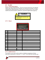
Document Name:
NV9 Range User Manual
Document Version:
1.1
Date of Release:
06/11/2019
TABLE OF CONTENTS
1 DOCUMENT INTRODUCTION .................................................................................................................. 4
1.1 RELATED DOCUMENTS ................................................................................................................................... 4
1.2 MANUAL AMENDMENTS ................................................................................................................................. 4
1.3 COPYRIGHT .................................................................................................................................................. 4
1.4 LIMITED WARRANTY ...................................................................................................................................... 4
1.5 PRODUCT SAFETY INFORMATION ...................................................................................................................... 5
2 PRODUCT INTRODUCTION ...................................................................................................................... 7
2.1 GENERAL DESCRIPTION ................................................................................................................................... 7
2.2 KEY FEATURES .............................................................................................................................................. 7
2.3 TYPICAL APPLICATIONS ................................................................................................................................... 7
2.4 COMPONENT OVERVIEW ................................................................................................................................ 7
2.5 BEZEL OPTIONS ............................................................................................................................................. 9
2.6 CASHBOX OPTIONS ........................................................................................................................................ 9
3 TECHNICAL DATA .................................................................................................................................. 10
3.1 DIMENSIONS .............................................................................................................................................. 10
3.2 WEIGHT(S) ................................................................................................................................................ 11
3.3 ENVIRONMENTAL REQUIREMENTS .................................................................................................................. 11
3.4 POWER REQUIREMENTS ............................................................................................................................... 11
3.4.1 Supply Voltages ............................................................................................................................. 11
3.4.2 Supply Currents ............................................................................................................................. 11
3.4.3 Power Supply Guidance ................................................................................................................ 12
3.5 INTERFACE LOGIC LEVELS .............................................................................................................................. 12
3.6 RELIABILITY DATA ........................................................................................................................................ 12
3.7 MEDIA REQUIREMENTS ................................................................................................................................ 13
3.7.1 Notes ............................................................................................................................................. 13
3.7.2 Tickets ........................................................................................................................................... 13
3.7.2.1 Ticket Dimensions ............................................................................................................................... 13
3.7.2.2 Barcode Requirements ....................................................................................................................... 13
4 MECHANICAL INSTALLATION ................................................................................................................ 16
4.1 COMPATIBILITY ........................................................................................................................................... 16
4.1.1 Hardware Compatibility ................................................................................................................ 16
4.1.1.1 Machine Mounting ............................................................................................................................. 16
4.1.1.2 Machine Interfacing ............................................................................................................................ 16
4.1.1.3 Power Supply ...................................................................................................................................... 17
4.1.2 Software Compatibility ................................................................................................................. 17
4.1.2.1 Interface Protocols .............................................................................................................................. 17
4.1.2.2 Re-programming ................................................................................................................................. 17
4.2 BEZEL MOUNTING ....................................................................................................................................... 18
4.2.1 Bezel Fitting .................................................................................................................................. 18
4.2.2 Bezel Removal ............................................................................................................................... 18
4.3 CASHBOX MOUNTING .................................................................................................................................. 19
4.3.1 Cashbox Fitting ............................................................................................................................. 19
4.3.2 Cashbox Removal .......................................................................................................................... 20
4.4 LOCK MOUNTING ........................................................................................................................................ 21
4.4.1 Lock Fitting .................................................................................................................................... 21
4.4.2 Lock Specifications ........................................................................................................................ 21

<< Back to Contents
Copyright © Innovative Technology Ltd 2019 Doc: NV9 Range User Manual
Version: 1.1
Page 2 of 70
4.4.3 Lock Cam ....................................................................................................................................... 22
4.5 MACHINE MOUNTING .................................................................................................................................. 23
4.5.1 Machine Mounting ....................................................................................................................... 23
4.5.2 Earth Bonding ............................................................................................................................... 23
5 SOFTWARE INSTALLATION AND CONFIGURATION ................................................................................ 24
5.1 INTRODUCTION ........................................................................................................................................... 24
5.2 SOFTWARE DOWNLOADS .............................................................................................................................. 24
5.3 DRIVERS .................................................................................................................................................... 24
5.4 DATASET/FIRMWARE PROGRAMMING ............................................................................................................ 24
5.4.1 Validator Manager........................................................................................................................ 24
5.4.1.1 General Description ............................................................................................................................ 24
5.4.1.2 System Requirements ......................................................................................................................... 24
5.4.1.3 Hardware Setup .................................................................................................................................. 25
5.4.1.4 Switching to Programming Mode (SSP) .............................................................................................. 26
5.4.1.5 Programming the device ..................................................................................................................... 26
5.4.2 DA3 ............................................................................................................................................... 27
5.4.2.1 General Description ............................................................................................................................ 27
5.4.2.2 System Requirements ......................................................................................................................... 27
5.4.2.3 Re-programming via DA3 .................................................................................................................... 28
5.4.2.4 SMART Update DA3 ............................................................................................................................ 29
5.4.3 Remote Updates ........................................................................................................................... 29
5.4.3.1 General Description ............................................................................................................................ 29
5.4.3.2 Software Requirements ...................................................................................................................... 29
5.4.4 Configuration Card ........................................................................................................................ 29
5.4.4.1 General Description ............................................................................................................................ 29
5.4.4.2 Hardware Requirements ..................................................................................................................... 30
5.4.4.3 Re-programming via Configuration Card ............................................................................................ 30
6 PROTOCOLS AND INTERFACING ............................................................................................................ 31
6.1 INTRODUCTION ........................................................................................................................................... 31
6.2 SSP AND ESSP ........................................................................................................................................... 31
6.2.1 General Description ...................................................................................................................... 31
6.2.2 Pin Assignments ............................................................................................................................ 31
6.2.3 Setup Examples ............................................................................................................................. 32
6.3 CCTALK
®
.................................................................................................................................................... 35
6.3.1 General Description ...................................................................................................................... 35
6.3.2 Pin Assignments ............................................................................................................................ 35
6.3.3 ccTalk
®
DES Encryption .................................................................................................................. 35
6.4 CC4 ......................................................................................................................................................... 37
6.4.1 General Description ...................................................................................................................... 37
6.4.2 Pinout ............................................................................................................................................ 37
6.5 SIO AND SI2 .............................................................................................................................................. 38
6.5.1 General Description ...................................................................................................................... 38
6.5.2 Pinout ............................................................................................................................................ 38
6.6 MDB ........................................................................................................................................................ 39
6.6.1 General Description ...................................................................................................................... 39
6.6.2 IF5 Interface .................................................................................................................................. 39
6.7 PARALLEL ................................................................................................................................................... 40
6.7.1 General Description ...................................................................................................................... 40
6.7.2 Pinout ............................................................................................................................................ 40
6.7.3 Inhibit Control ............................................................................................................................... 40
6.7.4 Escrow Control .............................................................................................................................. 41
6.7.5 IF10 Interface ................................................................................................................................ 41
6.8 BINARY ...................................................................................................................................................... 42
6.8.1 General Description ...................................................................................................................... 42
6.8.2 Pinout ............................................................................................................................................ 42
6.8.3 Inhibit Control ............................................................................................................................... 43
6.8.4 Escrow Control .............................................................................................................................. 43
6.8.5 IF9 Interface .................................................................................................................................. 43

<< Back to Contents
Copyright © Innovative Technology Ltd 2019 Doc: NV9 Range User Manual
Version: 1.1
Page 3 of 70
6.9 PULSE ....................................................................................................................................................... 44
6.9.1 General Description ...................................................................................................................... 44
6.9.2 Pinout ............................................................................................................................................ 44
6.9.3 Inhibit Control ............................................................................................................................... 44
6.9.4 Escrow Control .............................................................................................................................. 45
6.9.5 Credit Hold Function ..................................................................................................................... 45
6.9.6 IF15 Interface ................................................................................................................................ 45
7 ROUTINE MAINTENANCE ...................................................................................................................... 46
7.1 INTRODUCTION ........................................................................................................................................... 46
7.2 RECOMMENDED CLEANING INTERVALS ............................................................................................................ 46
7.3 RECOMMENDED BELT CHANGING INTERVALS .................................................................................................... 46
8 FIRST LEVEL SUPPORT ........................................................................................................................... 47
8.1 BEZEL LED FLASH CODES .............................................................................................................................. 47
8.2 STATUS LED FLASH CODES ............................................................................................................................ 47
8.3 CONFIGURATION BUTTON ............................................................................................................................. 48
8.4 DIL SWITCHES ............................................................................................................................................ 49
9 SECOND LEVEL SUPPORT ...................................................................................................................... 50
9.1 INTRODUCTION ........................................................................................................................................... 50
9.2 FAULT FINDING CHART ................................................................................................................................. 50
9.3 CLEARING A JAM ......................................................................................................................................... 51
9.4 CLEANING THE PRODUCT(S) .......................................................................................................................... 52
9.4.1 NV9USB+/NV11+ .......................................................................................................................... 52
9.4.2 Printer Head .................................................................................................................................. 53
9.5 CHANGING THE DRIVE BELTS ......................................................................................................................... 53
9.6 CLEARING A CHECKSUM ERROR ...................................................................................................................... 54
9.7 TESTING AFTER AN ERROR HAS BEEN CLEARED ................................................................................................... 55
9.8 RE-INITIALISATION OF THE SENSORS ................................................................................................................ 55
10 COMPLIANCES AND APPROVALS .......................................................................................................... 56
10.1 EC DECLARATION OF CONFORMITY ............................................................................................................ 56
11 APPENDIX ............................................................................................................................................. 57
11.1 CABLE DRAWINGS .................................................................................................................................. 57
11.1.1 CN00392 USB Type A to Validator Cable Assembly .................................................................. 57
11.1.2 CN00214 USB A to USB B Cable Assembly ............................................................................... 58
11.1.3 WR00147 Smart Payout to NV200 Adaptor Harness ............................................................... 59
11.1.4 CN00398 Dual ESSP Interface ................................................................................................... 60
11.1.5 WR02043 NVR280 Harness Power and Data ........................................................................... 61
11.2 CONNECTOR SPECIFICATIONS .................................................................................................................... 62
11.3 LOCK SPECIFICATIONS .............................................................................................................................. 62
11.4 MEDIA SPECIFICATIONS ........................................................................................................................... 63
11.5 SWITCHING TO PROGRAMMING MODE (SSP) .............................................................................................. 64
11.6 CCTALK DES ENCRYPTION – TRUSTED MODE ............................................................................................... 64
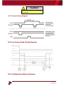
11.7 ESCROW CONTROL ................................................................................................................................. 66
11.7.1 Escrow Timing Diagram ........................................................................................................... 67
11.8 LOW POWER MODE TIMING DIAGRAM....................................................................................................... 67
11.9 CONFIGURATION BUTTON FUNCTIONS ........................................................................................................ 67
11.10 FILE NAMING CONVENTION ...................................................................................................................... 68
11.11 PROGRAMMING VIA CONFIGURATION CARD ................................................................................................ 69

<< Back to Contents
Copyright © Innovative Technology Ltd 2019 Doc: NV9 Range User Manual
Version: 1.1
Page 4 of 70
1 DOCUMENT INTRODUCTION
1.1 Related Documents
This document should be read together with the following:
For SSP/eSSP:
Protocol Manual – SSP (GA138) : SSP Interface Protocol Specification for integration
SSP Implementation Guide (GA973) : Information for programmers and integrators
For other third party interface protocols please contact support@innovative-
technology.com.
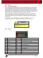
1.2 Manual Amendments
Rev.
Date
Amendment Details
Issued by
1.0
06/07/2017
First Issue
DH
1.1
06/11/2019
NV12 & Cables
HJ
1.3 Copyright
This manual set is Copyright © Innovative Technology Ltd. 2017. No part of this
publication may be reproduced in any form or by any means used to make any
derivative such as translation, transformation, or adaptation without permission from
Innovative Technology Ltd. The contents of this manual set may be subject to
change without prior notice.
1.4 Limited Warranty
Innovative Technology Ltd warrants each of its hardware products to be free from
defects in workmanship and materials under normal use and service for a period
commencing on the date of purchase from Innovative Technology Ltd or its
Authorized Reseller, and extending for the length of time stipulated by Innovative
Technology Ltd.
A list of Innovative Technology Ltd offices can be found in every section of this
manual set. If the product proves defective within the applicable warranty period,
Innovative Technology Ltd will repair or replace the product. Innovative Technology
Ltd shall have the sole discretion whether to repair or replace, and any replacement
product supplied may be new or reconditioned.
The foregoing warranties and remedies are exclusive and are in lieu of all other
warranties, expressed or implied, either in fact or by operation of law, statutory or
otherwise, including warranties of merchantability and fitness for a particular
purpose.
Innovative Technology Ltd shall not be liable under this warranty if it’s testing and
examination disclose that the alleged defect in the product does not exist or was
caused by the customer's or any third person's misuse, neglect, improper installation
or testing, unauthorized attempts to repair, or any other cause beyond the range of

<< Back to Contents
Copyright © Innovative Technology Ltd 2019 Doc: NV9 Range User Manual
Version: 1.1
Page 5 of 70
the intended use. In no event will Innovative Technology Ltd be liable for any
damages, including loss of profits, cost of cover or other incidental, consequential or
indirect damages arising out the installation, maintenance, use, performance, failure
or interruption of an Innovative Technology Ltd product, however caused.
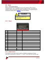
1.5 Product Safety Information
Throughout this user manual, we may draw your attention to key safety points that
you should be aware of when using or maintaining the product.
These safety points will be highlighted in a box, like this:
Caution!
This is an example text.
This user manual and the information it contains is only applicable to the model
stated on the front cover and must not be used with any other make or model.

<< Back to Contents
Copyright © Innovative Technology Ltd 2019 Doc: NV9 Range User Manual
Version: 1.1
Page 6 of 70
Safety Notice! Read before using this product!
Safety Notice - Warning. Ensure power is removed before allowing access to the inside of this product.
Ensure any static build up is discharged before allowing access to any part of this product or media
contained. Always earth this product/base plate in accordance with the manual.
For use only in or with complete equipment where the acceptability of the combination is determined by
UL LLC. When installed in an end-product, consideration must be given to the following:
• The power supply terminals and/or connectors are: Not investigated for field wiring
• The investigated Pollution Degree is: 2
• The following end-product enclosures are required: Mechanical, Fire
Sicherheitshinweis – Warnung: Es muss sichergestellt werden, dass das Gerät von der
Versorgungsspannung getrennt wird, bevor ein Eingriff in das Innere des Gerätes erfolgt. Es muss
sichergestellt werden, dass jegliche statische Aufladung des Gerätes entladen wird, bevor auf das Gerät
oder auf innerhalb des Gerätes befindliche Objekte zugegriffen wird. Die Erdung des Gerätes muss immer
gemäß Handbuch erfolgen.
Nur für die Verwendung in oder mit kompletter Ausstattung, dessen Eignung und Kombination von der UL
LLC ermittelt wurde. Bei der Installation in einem Endproduckt, muss folgendes berücksichtigt werden:
• Die Spannungsversorgungsklemmen und/oder Verbinder sind: Feldverkabelung wurde nicht
untersucht
• Der untersuchte Verschmutzungsgrad ist: 2
• Folgende Anforderungen an die Gehäuse des Endproduktes sind gefordert: Mechanisch, Feuer
Aviso de seguridad: Asegúrese de que la alimentación está desconectada y de que toda la energía
estática es descargada antes de manipular este producto. Conecte a tierra la chapa base de la manera que
se indica en el manual.
Solo para uso con dispositivos con los cuales la compatibilidad ha sido certificada por UL LLC. Tras su
instalación en producto acabado, tener en cuenta lo siguiente:
• Los conectores y terminales de alimentación son: No se ha investigado/especificado cableado
externo.
• El grado de contaminación determinado es: 2
• Los siguientes manuales/certificados de producto final son requeridos: Mecánico, Fuego
Avis de sécurité : Assurez-vous que l'alimentation est coupée et que toute l'énergie statique est
déchargé avant de manipuler ce produit. Connecter à la terre, la plaque de base à la manière indiquée
dans le manuel.
A utiliser Seulement avec les dispositifs dont la compatibilité a été certifiée par UL LLC. Après son
installation dans le produit fini, prendre en considération ce qui suit:-
• Les connecteurs et les bornes d'alimentation sont : cela n’a pas été étudié/spécifié câblage
externe.
• Le degré de contamination déterminé est: 2
• Les manuels suivants / les certificats du produit final sont nécessaires : mécanique, incendie
Bezpečnostní upozornění. Před manipulací uvnitř tohoto produktu se ujistěte, že je produkt odpojen od
zdroje elektrického napětí. Ujistěte se, že jakýkoliv elektrostatický náboj byl vybit před manipulací s
jakoukoliv částí tohoto produktu nebo obsaženým médiem. Vždy uzemněte tento produkt/základovou
desku v souladu s návodem.
Pouze pro použití v nebo s kompletním vybavením, kde je přijatelnost kombinace určena UL LLC. Při
instalaci v konečném produktu je třeba zvážit nasledující:
• Napájecí svorky a/nebo konektory: Nejsou sledované pro externí kabeláž
• Sledovaný stupeň znečištění je: 2
• Následující krytí konečného produktu jsou požadované: Mechanické, Protipožární

<< Back to Contents
Copyright © Innovative Technology Ltd 2019 Doc: NV9 Range User Manual
Version: 1.1
Page 7 of 70
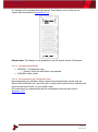
2 PRODUCT INTRODUCTION
2.1 General Description
The NV9 range are versatile banknote validators with cashbox and bezel options to suit all
applications, boasting enhanced sensing technology and a high acceptance rate for multi-
currency. The units can be mounted horizontally or vertically and exceptional field reliability
make them a truly global product range. A note float module can be added to provide note
recycling capability; and on the NV9USB+ a printer module can be added to allow for
printing and accepting of tickets.
2.2 Key Features
• Exceptional field reliability
• Enhanced sensing technology
• Cashbox and bezel options to suit all applications
• Future proof
o Add on recycler available. (NV11)
o Add on printer available. (NV12)
2.3 Typical Applications
• Amusement
• Vending
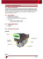
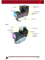
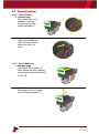
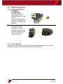
2.4 Component Overview
NV9USB+
NV11+


<< Back to Contents
Copyright © Innovative Technology Ltd 2019 Doc: NV9 Range User Manual
Version: 1.1
Page 9 of 70
2.5 Bezel Options
ITL Part Number
Description
Details
PA00188
NV9USB Vertical Up Bezel (82mm)
http://innovative-
technology.com/shop/bezels/nv9-vertical-up-
bezel-detail
PA00189
NV9USB Standard Horizontal Bezel (82mm)
http://innovative-
technology.com/shop/bezels/nv9-standard-
horizontal-bezel-detail
PA00190
NV9USB Vertical Up Snout Bezel (82mm)
http://innovative-
technology.com/shop/bezels/nv9-vertical-up-
snout-bezel-detail
PA00191
NV9USB Vertical Down Snout Bezel (82mm)
http://innovative-
technology.com/shop/bezels/nv9-vertical-down-
snout-bezel-detail
PA00268
NV9USB Horizontal Bezel (69mm)
http://innovative-technology.com/shop/nv9-a-
nv11-spares/nv9-horizontal-69mm-width-bezel-
detail
PA00296
NV9USB Vertical Up/Down Flat Bezel
(66mm)
http://innovative-technology.com/shop/nv9-a-
nv11-spares/nv9-66mm-vertical-updown-flat-
bezel-detail
PA00323
NV9USB Vertical Up/Down Flat Bezel
(69mm)
http://innovative-technology.com/shop/nv9-a-
nv11-spares/nv9-69mm-width-vertical-updown-
flat-bezel-detail
PA00896
NV11 Standard Bezel
http://innovative-technology.com/shop/nv9-a-
nv11-spares/nv11-standard-bezel-detail
PA01144
NV9USB+ Rainbow Bezel (82mm)
http://innovative-technology.com/shop/nv9-a-
nv11-spares/nv9-usb-rainbow-bezel-detail
PA00984
NV9USB Facia Short
http://innovative-technology.com/shop/nv9-a-
nv11-spares/nv9-usb-facia-short-detail
PA00985
NV9USB Facia Long
http://innovative-technology.com/shop/nv9-a-
nv11-spares/nv9-usb-facia-long-detail
2.6 Cashbox Options
ITL Part Number
Description
Details
PA00185
NV9 USB 300 Clip On Cashbox
http://www.innovative-
technology.com/shop/bezels/nv9-300-clip-on-
cashbox-detail
PA00186
NV9 USB 300 Lockable Cashbox
http://www.innovative-
technology.com/shop/bezels/nv9-300-lockable-
cashbox-detail
PA00192
NV9 USB 300 Slide Cashbox
http://www.innovative-
technology.com/shop/bezels/nv9-300-slide-
cashbox-detail
PA00193
NV9USB 600 Clip on Cashbox
http://innovative-technology.com/shop/nv9-a-
nv11-spares/nv9-600-clip-on-cashbox-detail
PA00194
NV9USB 600 Slide In Cashbox
http://innovative-technology.com/shop/nv9-a-
nv11-spares/nv9-600-slide-in-cashbox-detail
PA00898
NV11 Standard 300 Clip on Cashbox
http://innovative-technology.com/shop/nv9-a-
nv11-spares/nv11-standard-cashbox-detail

<< Back to Contents
Copyright © Innovative Technology Ltd 2019 Doc: NV9 Range User Manual
Version: 1.1
Page 10 of 70
3 TECHNICAL DATA
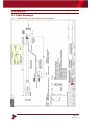
3.1 Dimensions
Note: If required, IGES 3D models are available on request from ITL technical
support; [email protected]

<< Back to Contents
Copyright © Innovative Technology Ltd 2019 Doc: NV9 Range User Manual
Version: 1.1
Page 11 of 70
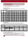
3.2 Weight(s)
NV9
NV9 300 clip with bezel – 1.41kg
NV9 300 slide with bezel – 1.86kg
NV9 600 clip with bezel – 1.72kg
NV9 600 slide with bezel – 2.14kg
NV11
NV9 300 clip with bezel + note float – 2.22kg
NV12
NV9 300 clip with bezel + NVR-280 printer – 2.2kg
3.3 Environmental Requirements
Environment
Minimum
Maximum
Temperature
+3°C
+3.7V to +12V
Humidity
5%
95% Non-condensing
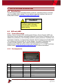
3.4 Power Requirements
3.4.1 Supply Voltages
Supply Voltage
Minimum
Nominal
Maximum
Supply Voltage (V DC)
+ 10.8 V DC
+ 12 V DC
+ 14.2 V DC
Supply Voltage (with IF5)
18 V DC
---
48 V DC or 34 V AC
Supply Ripple Voltage
0 V
0 V
0.25 V @ 100 Hz
3.4.2 Supply Currents
NV9USB+
Supply Current
Minimum
Nominal
Maximum
Standby
--
--
0.2 A
Running
--
--
1.0 A
Peak
--
--
1.5 A
NV11+
Supply Current
Minimum
Nominal
Maximum
Standby
--
--
0.35 A
Running
--
--
3.0 A
Peak
--
--
3.5 A
NV12+
Supply Current
Minimum
Nominal
Maximum

<< Back to Contents
Copyright © Innovative Technology Ltd 2019 Doc: NV9 Range User Manual
Version: 1.1
Page 12 of 70
Standby
--
--
0.35 A
Running
--
--
2.0 A
Peak
--
--
5.0 A
3.4.3 Power Supply Guidance
The NV9 Range of products require a stable 12V DC power supply. Please check the
power requirements of your host machine and other peripherals to dimension a
suitable power environment for your machine setup.
TDK Lambda manufactures suitable power supplies. Please see table below for
further details.
Power Supply
Unit
Specification
RS Stock Code
Farnell Stock
Code
Suitable for
use:
TDK Lambda SWS50-
12
+12 V DC / 4.3 A
466-5869
1184645
NV9USB+
NV11+
TDK Lambda SWS75-
12
+12 V DC / 6.3 A
466-5904
1184648
NV12+
3.5 Interface Logic Levels
Interface Logic Levels
Logic Low
Logic High
Inputs
0V to +0.5V
+3.7V to +12V
Outputs with 2K2Ω pull-up resistor
+0.6V
Pull-up voltage of host interface
Maximum Current Sink
50mA per Output
3.6 Reliability Data
The below data refers to the Mean Cycles Between Failure (MCBF) and the Mean
Cycles Between Intervention (MCBI). The difference between the two is that a
failure would usually require the unit being replaced. Whereas an intervention would
be an issue that is easily clearable such as a reset or clearing a note path jam.
A cycle is classed as a note or ticket being either accepted or dispensed. For
example; if a unit accepts a note and then dispenses a note as change, it is classed
as two cycles.
NV9USB+
MCBF: 200,000 Cycles
MCBI: 100,000 Cycles
It is important to note that when adding a recycler or printer, you are doubling the
number of modules. Thus, the MCBF/MCBI will naturally be halved.
NV11+
MCBF: 100,000 Cycles
MCBI: 50,000 Cycles

<< Back to Contents
Copyright © Innovative Technology Ltd 2019 Doc: NV9 Range User Manual
Version: 1.1
Page 13 of 70
NV12+
MCBF: 100,000 Cycles
MCBI: 50,000 Cycles
3.7 Media Requirements
3.7.1 Notes
Minimum
Maximum
Length
90mm
170mm
Width
62mm
82mm
The NV9 range supports multiple currencies and denominations as per the
specifications detailed in the table above. Furthermore polymer and windowed notes
are in use in a number of countries and so are already fully supported on the NV9
range of validators.
3.7.2 Tickets
The NV9USB+ validator is only able to read and accept barcode tickets, if the printer
module is attached (NV12+). The below information specifies the ticket dimensions
as well as the barcode requirements.
3.7.2.1 Ticket Dimensions
Tickets should have a width (A) of 65mm to 82mm, the smaller the ticket the larger
barcode width should be used.
The length (B) of the ticket is variable, tickets between 90mm and 166mm are
acceptable.
3.7.2.2 Barcode Requirements
The interface the validator is operating in will change the possible value of the
barcode number.
SSP: Barcode length can be between 6 to 24 characters.
ccTalk: Barcode length is fixed to 18 characters, however this is configurable.

<< Back to Contents
Copyright © Innovative Technology Ltd 2019 Doc: NV9 Range User Manual
Version: 1.1
Page 14 of 70
Dimension
The barcode itself should be no thinner (E) than 10mm. The narrow bar width
between 0.5mm and 0.6mm, with the wide narrow ratio (W:N) being 2:1.
A blank space (C) is required on either side of the barcode as pictures or text may
be seen as part of the barcode value.
This space should be 10mm.
Positioning
The barcode itself should be centred along the width (D) on the ticket.
Complete Ticket
Barcode
Characteristic
Details
Dimension
Details

<< Back to Contents
Copyright © Innovative Technology Ltd 2019 Doc: NV9 Range User Manual
Version: 1.1
Page 15 of 70
Narrow Bar Width
Minimum: 0.5mm
Maximum: 0.6mm
A
65mm to 82mm
W:N Ratio
2:1
B
90mm to 166mm
Number of Characters
Minimum: 6
Maximum: 24
C
Minimum 10mm
D
Barcode must be centred
E
Minimum 10mm

<< Back to Contents
Copyright © Innovative Technology Ltd 2019 Doc: NV9 Range User Manual
Version: 1.1
Page 16 of 70
4 MECHANICAL INSTALLATION
4.1 Compatibility
4.1.1 Hardware Compatibility
4.1.1.1 Machine Mounting
Assuming the suitable bezel (and cashbox) type has been ordered the NV9USB
range can be used as fitting replacement for the following products:
• NV7
• NV7M
• NV9
Please note: Considerations will need to be made when adding either the recycler
or printer module, as this will increase the space requirements inside the host
machine.
The NV11+ and NV12+ have the same space envelope so swapping the recycler for
the printer will not require any mechanical adjustments.
Innovative Technology Ltd. has a policy of continuous product improvement. Due to
design changes, older model or product bezels (and cashboxes) may not be
compatible with the current NV9USB+. However, new product deliveries always
include a bezel (and cashbox) that must be used.
4.1.1.2 Machine Interfacing
By design the NV9USB+ and NV11+ are pin to pin compatible with the fitting
replacement products listed above. No changes to existing machine harnessing are
required.
The NV12+ has an additional connector, in order to power and communicate with
the printer head.

<< Back to Contents
Copyright © Innovative Technology Ltd 2019 Doc: NV9 Range User Manual
Version: 1.1
Page 17 of 70
4.1.1.3 Power Supply
It is vital that the product is connected to a power supply being able to provide the
required power environment. A weak power supply can lead to unexpected
behaviour such as note rejects or missing credits. If you are replacing an older
model or product we recommend checking the power supply specifications of the
machine. The newer models might have higher power consumption. Refer to 3.4 for
full power requirement details of the full NV9 range.
4.1.2 Software Compatibility
4.1.2.1 Interface Protocols
When using the NV9 range of products as a fitting replacement for an older model or
product some events such like credits may be given earlier. This is due to improved
firmware routines and faster motors being used. This may cause missing events
such like credits in those host machines where timeouts are defined for the older
model or product. Please contact the machine manufacturer for full compatibility.
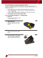
4.1.2.2 Re-programming
For re-programming the units always use the latest version of Validator Manager,
available for download from our website. Newer products may not be fully supported
on older versions of Validator Manager. For further details on Re-programming, refer
to 5.4.

<< Back to Contents
Copyright © Innovative Technology Ltd 2019 Doc: NV9 Range User Manual
Version: 1.1
Page 18 of 70
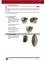
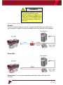
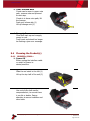
4.2 Bezel Mounting
4.2.1 Bezel Fitting
1. Locator lugs
Place bezel down onto
validator, ensuring
locating lugs go into
spaces provided (1).
2. Lock bezel in place
Slide bezel backwards
until you hear release
latch arm, click into
place.
4.2.2 Bezel Removal
1. Release clips
Pull release clip upwards (1)
With release clip held upwards,
you can pull bezel towards front
of unit (2).
2. Lift Bezel
Now bezel is free of locating
lugs, lift bezel upwards (3).

<< Back to Contents
Copyright © Innovative Technology Ltd 2019 Doc: NV9 Range User Manual
Version: 1.1
Page 19 of 70
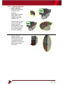
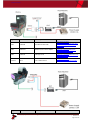
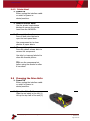
4.3 Cashbox Mounting
Below you will find details on how to fit the different cashboxes mentioned in section
2.6.
Slide cashboxes are made up of 2 x parts. The outer housing and the cashbox itself,
which slides in and out of the housing. These are used for when the unit is mounted
horizontally.
Clip on cashboxes attach directly onto the validator. These are mainly used for when
the unit is mounted vertically.
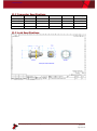
4.3.1 Cashbox Fitting
1. Slide Cashbox
The outer housing has 2 x
lugs on either side and these
need to be pushed up into
the cashbox slots as per the
image.
Then slide housing forwards
to lock into place.
The outer housing is
mounted inside the machine
and you simply slide the
removable cashbox, inside
the outer housing.
2. Clip-on Cashbox
The clip-on cashbox attaches
directly to the validator and
is identical to the process
above.
Seite wird geladen ...
Seite wird geladen ...
Seite wird geladen ...
Seite wird geladen ...
Seite wird geladen ...
Seite wird geladen ...
Seite wird geladen ...
Seite wird geladen ...
Seite wird geladen ...
Seite wird geladen ...
Seite wird geladen ...
Seite wird geladen ...
Seite wird geladen ...
Seite wird geladen ...
Seite wird geladen ...
Seite wird geladen ...
Seite wird geladen ...
Seite wird geladen ...
Seite wird geladen ...
Seite wird geladen ...
Seite wird geladen ...
Seite wird geladen ...
Seite wird geladen ...
Seite wird geladen ...
Seite wird geladen ...
Seite wird geladen ...
Seite wird geladen ...
Seite wird geladen ...
Seite wird geladen ...
Seite wird geladen ...
Seite wird geladen ...
Seite wird geladen ...
Seite wird geladen ...
Seite wird geladen ...
Seite wird geladen ...
Seite wird geladen ...
Seite wird geladen ...
Seite wird geladen ...
Seite wird geladen ...
Seite wird geladen ...
Seite wird geladen ...
Seite wird geladen ...
Seite wird geladen ...
Seite wird geladen ...
Seite wird geladen ...
Seite wird geladen ...
Seite wird geladen ...
Seite wird geladen ...
Seite wird geladen ...
Seite wird geladen ...
-
 1
1
-
 2
2
-
 3
3
-
 4
4
-
 5
5
-
 6
6
-
 7
7
-
 8
8
-
 9
9
-
 10
10
-
 11
11
-
 12
12
-
 13
13
-
 14
14
-
 15
15
-
 16
16
-
 17
17
-
 18
18
-
 19
19
-
 20
20
-
 21
21
-
 22
22
-
 23
23
-
 24
24
-
 25
25
-
 26
26
-
 27
27
-
 28
28
-
 29
29
-
 30
30
-
 31
31
-
 32
32
-
 33
33
-
 34
34
-
 35
35
-
 36
36
-
 37
37
-
 38
38
-
 39
39
-
 40
40
-
 41
41
-
 42
42
-
 43
43
-
 44
44
-
 45
45
-
 46
46
-
 47
47
-
 48
48
-
 49
49
-
 50
50
-
 51
51
-
 52
52
-
 53
53
-
 54
54
-
 55
55
-
 56
56
-
 57
57
-
 58
58
-
 59
59
-
 60
60
-
 61
61
-
 62
62
-
 63
63
-
 64
64
-
 65
65
-
 66
66
-
 67
67
-
 68
68
-
 69
69
-
 70
70


innovative technology NV11+ Technical Manual
- Typ
- Technical Manual
in anderen Sprachen
- English: innovative technology NV11+
Verwandte Artikel
Andere Dokumente
-
Phanteks NV9 Premium LED Kit Bedienungsanleitung
-
Acclaim Lighting APS-240-24 Installationsanleitung
-
 TDK-Lambda RFE1600-32 Installationsanleitung
-
 StarTech com A-LAPTOP-DESK-MOUNT Benutzerhandbuch
-
-
 TDK-Lambda Alpha 1000 Benutzerhandbuch
-
Wincor Nixdorf Value Line 3010-5020 Benutzerhandbuch
-
Samsung NV9 Schnellstartanleitung
-
Samsung SAMSUNG NV9 Benutzerhandbuch
-


