
User and
Maintenance Manual
Warranty information
FLOW MASTER
VOLUMETRIC FLOW METER
FOR CONTROLLING THE FLOW OF LIQUIDS.
MANUAL OR MOTORIZED ADJUSTMENT
http://www.dropsa.com
Manual drafted in compliance with
EC Directive 98/37
C2057IE – WK 01/12
TABLE OF CONTENTS
1. INTRODUCTION
2. GENERAL DESCRIPTION
3. PRODUCT-MACHINE IDENTIFICATION
4. TECHNICAL CHARACTERISTICS
5. MACHINE COMPONENTS
6. UNPACKING AND INSTALLING THE MACHINE
7. MACHINE OPERATIONS
8. TROUBLESHOOTING
9. MAINTENANCE PROCEDURE
10. DISPOSAL
11. ORDERING INFORMATION
12. DIMENSIONS
13. HANDLING AND TRANSPORTATION
14. OPERATING HAZARDS
15. PRECAUTIONS
16. WARRANTY INFORMATION
17. DECLARATION OF COMPLIANCE WITH STANDARDS
18. DROPSA LOCATIONS

2
1. INTRODUCTION
This manual refers to FLOW MASTER volumetric flow device.
You can find additional copies and newer revisions of this document from our website http://www.dropsa.com. Alternatively
contact one of our Sales Offices.
This User and Maintenance Manual contains important information on health and safety issues for the personnel.
It is recommended to attentively read this manual and carefully keep it in good condition so that it is always available to
personnel requiring to consult it.
2. GENERAL DESCRIPTION
FLOW MASTER is a volumetric flow meter, which constantly monitors lubrication.
Flow meter precise monitoring, without calibrations or adjustments, is due to volumetric measurements not dependent on
lubricant temperature or viscosity.
FLOWMASTER is a modular system consisting of two elements:
Base
Metering module
MODULAR SYSTEM
The base is common to all size modules, which are also interchangeable. The modular construction makes it possible to built
assys (base and metering module) of 20 modules or more.
OPERATING PRINCIPLE
A “satellite”, which rotates with a fixed orbital movement, is operated by the liquid passage through the metering module. An
inductive sensor picks up each orbital movement and transmits a signal to an electronic reader. The operator can read the
output of the metering module in litres/min or in rev/min directly from the FACT 2000 device-display or from a PC monitor.
VISUAL INDICATION OF THE FLOW OF LIQUID
A “satellite”, built in the module body, rotating with an orbital movement indicates the fluid velocity. The flow output is neither
reduced nor interrupted even if the “satellite” stops.
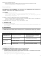
3. PRODUCT - MACHINE IDENTIFICATION
Machine identification red label is located on the front side of the unit and contains machine serial number.

3
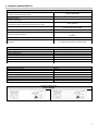
4. TECHNICAL CHARACTERISTICS
Proximity Inductor Sensor
Electric Diagram
Base and metering module
Fluid maximum viscosity
(at lubricant operating temperature)
1000 cSt (4628 SUS)
Operating temperature
-20 C ÷ +60 C (-4 °F ÷ +140 °F)
Minimum pressure
(continuous working)
6 bar (88.2 psi)
Maximum pressure
(intermittent working; maximum operating time: 1 hour)
20 bar (294 psi)
Base threads
-Inlet G”1/2 UNI-ISO 228/1-
- Outlet G” 3/8 UNI-ISO 228/1 -
Seals
O-Ring in Viton
Bases and metering modules
Stainless steel AISI 316
or
aluminium
Cover
Transparent polyamide
Maximum distance between a flow meter and the Electronic Control
Equipment
15 metres (16.4 yard)
It is advisable the use of a shielded cable
Motor for output adjustment
Supply voltage
12V DC
Reduction ratio
392:1 – Max torque: 3 Kg/cm (6.61 lb/cm)
Rev/min without load
6
Rev/min with max torque
5
Current consumption without load
15 mA
Current consumption with max torque
30mA
Revolution direction
reversible
Proximity Inductive Sensor
Maximum output current
200 mA
Supply voltage
10 ÷ 30V D.C.
Maximum switching frequency
200 Hz
Current consumption at 24 V D.C.
<18 mA
Outputs
NPN or PNP
Protection grade
IP 67
Temperature
-25 °C ÷ +70 °C (-13 °F ÷ + 158 °F)

4
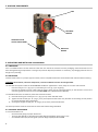
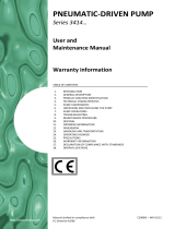
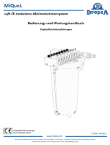
5. MACHINE COMPONENTS
6. UNPACKING AND INSTALLING THE MACHINE
6.1 UNPACKING
Once a suitable location has been found to install the unit remove the machine from the packaging. Check the device has not
been damaged during transportation or storage. No particular disposal procedures are necessary, as packaging materials are not
dangerous or polluting.
6.2 INSTALLING
Install the flow meter on a proper support surface, free from impediments which could interfere with machine well functioning.
WARNING: All the electric, electronic components, reservoirs and base structure must be grounded.
The stainless steel option makes the FLOW MASTER suitable for applications in harsh, damp or corrosive environments.
- Connect inlet (par. 11.3, fig.1, pos. J) and outlet (par. 11.3, fig.1, pos. K) piping.
- Connect the inductive sensor cables (and the motor cables, for the motorized option) to the electronic control and
monitoring equipment terminal strip (see FACT 2000 User and Maintenance Manual).
To assemble flow meters in batteries, follow the instructions below:
1) Unscrew the two grub screws (par. 11.3, fig.1, pos.1) of the next flow meter.
2) Tighten the two screws (par. 11.3, fig.1, pos.2) to the previous flow meter. Pay attention to the O-Ring correct position
to prevent damages during assembling.
3) Screw again the grub screws (par. 11.3, fig.1, pos.1) to the previous flow meter.
The above operations must be carried out for all the flow meters being assembled.
6.3 TECHNICAL INDICATIONS
It is recommended to use:
- Structural steel piping of proper dimensions
- Grip-ring pipe fittings (To assembly: block pipe fittings and tighten pipes using a vice)
- An inlet filter with a proper filter grade (not over 90µ), Dropsa part N°3130309
BASE
METERING
MODULE
INDUCTIVE
SENSOR
GEAR MOTOR FOR
OUTPUT ADJUSTMENT

5
If the machine is operated for the first time:
1. Decrease oil pumping unit pressure and ensure that all the connections are correct and there are no leaks.
2. Increase pressure progressively to suit individual flow requirements.
7. PUMP OPERATIONS
MANUAL OPTION
Output adjusting of the manual FLOWMASTER is easy: through the use of two needle valves the output adjustment can be
coarsely (par. 11.3, fig.1, pos. X) or finely adjusted (par. 11.3, fig.1, pos. Y).
To coarsely adjust:
1. Unlock the locknut of the needle valve.
2. Close the fine adjustment valve (par. 11.3, fig.1, pos. Y), by turning clockwise with a M3 allen spanner.
3. Increase or decrease the output by turning counterclockwise or clockwise, with a M5 allen spanner, the coarse
adjustment valve (par. 11.3, fig.1, pos. X).
It is advisable to make the fine adjustment only after the coarse adjustment, as follows:
- Increase or decrease the output by turning counterclockwise or clockwise, with a M3 allen spanner, the fine adjustment
valve (par. 11.3, fig.1, pos. Y) to suit individual flow requirements.
The fine adjustment valve (par. 11.3, fig.1, pos. Y) only is used for the size “A” module.
7.1 MOTORIZED OPTION
To adjust motorized FLOWMASTER output:
- Close the fine adjustment valve (par. 11.3, fig.1, pos. Y) and let the electronic control equipment start automatically in line
with the setting data.
8. TROUBLESHOOTING
The following diagnostic table indicates the main anomalies, which may be encountered, the probable causes and possible
solutions.
If you cannot solve the problem, do not attempt to disassemble parts of the machine but contact the Engineering Department of
DROPSA S.p.A., pointing out anomaly details.
9. MAINTENANCE PROCEDURE
FLOW MASTER has been designed and constructed to require a minimum of maintenance.
For an easy maintenance, it is advised to assemble the machine in an adequate location.
- To facilitate maintenance tasks without interrupting the operation of the machine, it is recommended to provide the flow
meter with an input ball valve to disconnect parts of the system.
- Periodically check pipe-joints to detect possible leaks.
- Always keep the machine unit clear to readily detect possible leaks.
- Periodically (once a year or when required) replace the refilling filter, part n°: 3130139.
ANOMALY
PROBABLE CAUSE
SOLUTION
No signal transmitted by
the flow meter
Wrong electrical connection
→ Check sensors (and motor, for the motorized
option) electrical connections on the control
equipment terminal strips
Blocked satellite
Impure oil in the circuit
→ Check and clean the oil output circuit filtering
cartridges. Replace them, if necessary
Abnormal satellite
rotation
Cold oil in the circuit
→ Act on the pumping system electrical resistance
Low pressure
→ Increase pressure
Oil leakage
Worn O-ring seals
→ Replace the seals.
(see machine parts drawing, par. 11.3)

6
The machine does not require any special tool for check or maintenance tasks. However, it is recommended the use only of
appropriate and in good conditions tooling, protective devices (gloves) and clothing (626/94 and DPR 547/55) to avoid injury to
persons or damage to machine parts.
WARNING: Before any maintenance procedure, be sure that power, hydraulic and pneumatic supplies are off.
10. DISPOSAL
During maintenance or disposal of the machine care should be taken to properly dispose of environmentally sensitive items.
Refer to local regulations in force in your area.
When disposing of this unit, it is important to ensure that the identification label and all the other relative documents are also
destroyed.
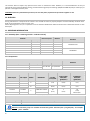
11. ORDERING INFORMATION
11.1 Assembly (base –metering module – inductive sensor)
Manual option
SERIAL N°
Motorized option
METERING
MODULE
MATERIAL
NPN output
PNP output
SERIAL N°
MODEL
1523730
1523870
1523950
A
STAINLESS STEEL
1523740
1523880
1523960
B
1523750
1523890
1523970
C
1523732
1523872
1523952
A
ALUMINIUM
1523742
1523882
1523962
B
1523752
1523892
1523972
C
11.2 Components
BASE
PART N°
THREADS
MATERIAL
Manual option
Motorized option
Inlet
Outlet
1523330
1523630
G ½ UNI-ISO
G 3/8 UNI-ISO
STAINLESS STEEL
1523332
1523632
ALUMINIUM
METERING MODULE
PART N°
NPN output
PNP output
MODEL
MATERIAL
FLOWRATE
cm³/min.
(cu.in.)/min.
MIN FLOWRATE
at 50 rev/min.
litres/min.
(galls/min.)
MAX FLOWRATE
at 1000/min.
litres/min.
(galls/min.)
1523734
1523874
A
STAINLESS STEEL
5
(0.3)
0.25
(0.05)
5
(1.1)
1523735
1523875
ALUMINIUM
1523744
1523884
B
STAINLESS STEEL
10
(0.61)
0.5
(0.11)
10
(2.2)
1523745
1523885
ALUMINIUM
1523754
1523894
C
STAINLESS STEEL
20
(1.22)
1
(0.22)
16
(3.52)
800 rev/min.
1523755
1523895
ALUMINIUM
INDUCTIVE SENSOR
PART N°
NPN output
PNP output
1523739
1523812
NOTICE: Pre-mounted groups are available for flowrates greater than 20 lt/min. (4.4 galls/min.): for example:
part n° 1524475.

7
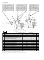
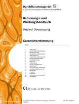
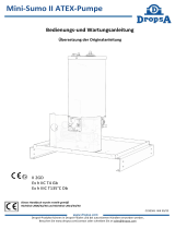
11.3 Spare parts
* O-Ring is built-in for 9 - 9a – 10 modules.
O-Ring Pos. 4 must be mounted only between base and base.
Screws (Pos. 11), Gasket (Pos. 5) and Plug (Pos. 6) must be ordered separately.
Pos.
Description
Part N°
(stainless steel)
Part N°
(aluminium)
Q.ty
1
Grub screw
675217
1523343
2
2
Screw
675230
14093
2
3
Base, threads UNI-ISO, completed with motor (X1), screws (Y), grub
screws (pos. 1), screws (pos. 2), O-Ring (pos. 4,12,13,14)
1523630
1523632
1
3A
Base threads UNI-ISO completed with grub screws (pos. 1), screws (X)
and (Y), screws (pos. 2), O-Ring (pos. 4,12,13,14)
1523330
1523332
1
4
O-Ring in Viton
1523352
1523352
1
5
Gasket
3190319
3190318
1
6
Plug - Threads G 1/4 UNI-ISO 228/1
3234207
3234206
1
7
Screw for metering module “A” 5 cm³ (0.3 cu.in.)
14165
14069
4
7
Screw for metering module “B” 10 cm³ (0.61 cu.in.)
14175
12769
4
7
Screw for metering module “C” 20 cm³ (1.22 cu.in.)
14177
14176
4
8
Sensor
1523739
1523739
1
9
Metering module “B” (completed with screw pos. 7)
1523744
1523745
1
9a
Metering module “C” (completed with screw pos. 7)
1523754
1523755
1
10
Metering module “A” (completed with screw pos. 7)
1523734
1523735
1
*
O-Ring in Viton for metering module
1523353
1523353
1
11
Screw
14157
14081
2
12
O-Ring in Viton
1523349
1523349
2
13
O-Ring in Viton for fine adjustment valve
1523354
1523354
1
14
O-Ring in Viton for coarse adjustment valve (motorized)
1523397
1523397
1
X1
Output adjustment unit with ratiomotor
1523692
1523691
1
MOTORIZED
MANUAL
Connector for pipe,
complete with nut and ring
Connector for pipe,
complete with nut and ring
Connector with check valve,
complete with nut and ring
Ø Pipe
Part N°
Ø Pipe
Part N°
Ø
Pipe
Part N°
for
stainless steel
base
for
aluminium
base
for stainless
steel base
for
aluminium
base
for
stainless steel
base
for
aluminium
base
mm
in.
mm
in.
mm
in.
10
0.39
530051
92374
8
0.31
530050
92363
8
0.31
530063
92368
12
0.47
530052
92375
10
0.39
530042
92270
10
0.39
530064
92369
16
0.62
530045
92376
12
0.47
530043
92254
12
0.47
530065
92370
Fig.1
J
K

8
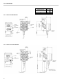
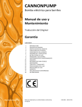
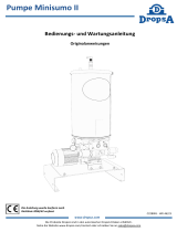
12. DIMENSIONS
12.1 Manual FLOW MASTER
12.2 Motorized FLOW MASTER
Depth “X”
mm
in.
Module metering
“A”
60
2.36
“B“
67.5
2.65
“C“
82
3.22

9
13. HANDLING AND TRANSPORTATION
Given the low weight and small dimensions of the machine, it is not necessary the use of material handling equipment.
Prior to shipping, the machine is carefully packed in cardboard packing.
During transportation and storage, pay attention to the side on the cardboard packing.
On receipt, check that the packing is not damaged and then, storage the machine in a dry location.
14. OPERATING HAZARDS
It is necessary to read carefully about the instructions and the risks involved in the use of lubrication components. The
operator must know machine functioning and dangers through the user manual.
Power supply
Any type of intervention must not be carried out before the unplugging of the machine from the power supply. Make sure that
no one can start it up again during the intervention.
All the installed electric and electronic equipment, reservoirs and basic components must be grounded.
Inflammability
The lubricant generally used in lubrication systems is not normally inflammable. However, it is advised to avoid contact with
extremely hot substances or naked flames.
Pressure
Prior to any intervention, check the absence of residual pressure in any branch of the lubricant circuit as it may cause oil sprays
when disassembling components or fittings.
Noise and vibrations
FLOW MASTER does not produce excessive noise, less than 70 dB(A).
15. PRECAUTIONS
No particular operating hazards characterize the FLOW MASTER, except for the following precautions:
Operator’s contact with lubricant during maintenance tasks:
The operator must be provided with suitable personal protective clothing and devices.
Use of incompatible lubricant:
MAIN NO COMPATIBLE FLUIDS
Fluids
Dangers
Lubricants containing abrasive components
Premature wear of pump
Lubricants containing silicon
Pump failure
Petrol – solvents – inflammable liquids
Fire – explosion –seal damage
Corrosive products
Pump damage - danger to persons
Water
Pump oxidization
Food Products
Contamination of the product
CAUTION: During storage, machine components can withstand temperatures –20 °C ÷ +60 °C (-4 °F ÷ +140 F°).
However, in order to avoid damages, machine starting should occur at a minimum temperature of +5 °C (+41
°F).

10
16. WARRANTY INFORMATION
All products manufactured and marketed by Dropsa are warranted to be free of defects in material or workmanship for a period
of at least 12 months from date of delivery. Extended warranty coverage applies as follows:
Complete system installation by Dropsa: 24 Months
All other components: 12 months from date of installation; if installed 6 months or more after ship date, warranty shall be
maximum of 18 months from ship date.
If a fault develops, notify us giving a complete description of the alleged malfunction. Include the part number(s), test record
number where available (format xxxxxx-xxxxxx), date of delivery, date of installation and operating conditions of subject
product(s).
We will subsequently review this information and, at our option, supply you with either servicing data or shipping instruction
and returned materials authorization (RMA) which will have instructions on how to prepare the product for return.
Upon prepaid receipt of subject product to an authorized Dropsa Sales & Service location, we will then either repair or replace
such product(s), at out option, and if determined to be a warranted defect, we will perform such necessary product repairs or
replace such product(s) at our expense.
Dropsa reserves the right to charge an administration fee if the product(s) returned are found to be not defective.
This limited warranty does not cover any products, damages or injuries resulting from misuse, neglect, normal expected wear,
chemically caused corrosion, improper installation or operation contrary to factory recommendation. Nor does it cover
equipment that has been modified, tampered with or altered without authorization.
Consumables and perishable products are excluded from this or any other warranty.
No other extended liabilities are stated or implied and this warranty in no event covers incidental or consequential damages,
injuries or costs resulting from any such defective product(s).
The use of Dropsa product(s) implies the acceptance of our warranty conditions. Modifications to our standard warranty must
be in made in writing and approved by Dropsa.

11
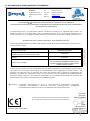
17. DECLARATION OF COMPLIANCE WITH CE STANDARDS
La persona autorizzata a costituire il Fascicolo Tecnico c/presso Dropsa S.P.A.
The person authorized to compile the Technical File care of Dropsa S.P.A.
Vimodrone (MI), Gennaio 2012
Dropsa Spa
Via Benedetto Croce, 1
20090 Vimodrone (MI)
Italy
Tel.:
Fax Sales:
E-mail:
Web site:
DICHIARAZIONE DI CONFORMITÁ/DECLARATION OF COMPLIANCE WITH STANDARDS/
DECLARATION DE CONFORMITE/ KONFORMITÄTSERKLÄRUNG DES STANDARDS /DECLARACIÓN DE CONFORMIDAD/
DECLARAÇÃO DE CONFORMIDADE
La società Dropsa S.p.A., con sede legale in Milano, Via Besana,5/ Dropsa S.p.A., registered office in Milan, Via
Besana,5 / Dropsa S.p.A. au Siège Social à Milan, Via Besana,5/ Dropsa S.p.A., Sitz in Milano, Via Besana 5/ La
sociedad Dropsa S.p.a., con sede legal en Milán, Via Besana,5/ A Dropsa S.p.A, com sede em Milão, via Besana, nº 5
DICHIARA /CERTIFIES / CERTIFIE/ ZERTIFIZIERT, DASS/ DECLARA/ CERTIFICA:
che il prodotto denominato/that the product called/ le produit appelè/ das Produkt mit dem Namen/ el producto que se
llama/ o produto chamado:
Descrizione/ Description/ Description/ Beschreibung/
Descripción/ Descrição:
Misuratore di portata
Volumetric flow meter
Nome Commerciale/ Product Name/ Dénomination/
Handelsname/ Denominación/ Denominação:
Flowmaster
Versioni/ Versions/ Versions/ Versionen/ Versiones/
Versões:
All versions
Codici/ Codes/ Códigos/:
1523730-1523740-1523750-1523732-1523742-
1523752-1523870-1523880-1523890-1523872-
1523882-1523892-1523950-1523960-1523970-
1523952-1523962-1523972
è conforme alle condizioni previste dalle Direttive CEE /has been constructed in conformity with the Directives Of
The Council Of The European Community on the standardization of the legislations of member states/ a été
construite en conformité avec les Directives Du Conseil Des Communautes Europeennes/ Entsprechend den
Richtlinien des Rates Der Europäischen Union, für die Standarisierung der Legislative der Mitgliederstaaten,
konstruiert wurde/ cumple con las condiciones establecidas por las directivas comunitarias/ foi construído em
conformidade com as diretivas do Conselho das Comunidades Europeias:
2004/104 CE Compatibilità elettromagnetica dei veicoli a motore/ Automotive Electromagnetic Compatibility/
Compatibilité électromagnétique automobile/ Automotive Elektromagnetische Verträglichkeit/
Compatibilidad Electromagnética Automotriz/ Compatibilidade Eletromagnética Automotive
Technical
Director:
Maurizio Greco
..........................
Legal
representative
Milena Gavazzi
...............................
......

12
18. DROPSA LOCATIONS
Dropsa S.p.A.
Via B. Croce,1
20090 Vimodrone (MI) Italy.
Tel: (+39) 02 - 250.79.1
Fax: (+39) 02 - 250.79.767
E-mail: [email protected] (Export)
E-mail: [email protected] (National)
Dropsa Ame
23, Av.des.Morillons
Z.I. des Doucettes 91140
Garges Les Gonesse, France
Tel: (+33) 01 39 93 00 33
Fax: (+33) 01 39 86 26 36
E-mail: [email protected]
Dropsa (UK) Ltd
Unit 6, Egham Business Village,
Egham,Surrey,TW20 8RB
Tel: (+44) 01784 - 431177
Fax: (+44) 01784 - 438598
E-mail: [email protected]
Dropsa do Brazil Ind. E Com. Ltda
Rua Sobralia 175,
Sao Paulo, Brazil
Tel: (+55) 011-5631-0007
Fax: (+55) 011-5631-9408
E-mail: [email protected]
Dropsa USA Inc.
6645 Burroughs Ave
48314-2132 Srerling Hts,Mi Us -USA
Tel: (+1) 586-566-1540
Fax: (+1) 586-566-1541
E-mail: [email protected]
Dropsa Lubrication Systems
Nr 8 Dongxing Road,
Songjiang Industrial Zone
(Shanghai) Co., Ltd
Tel: +86 (021) 67740275
Fax: +86 (021) 67740205
E-mail: [email protected]
Dropsa Gmbh
Volmerswerther Strasse 80
40221 Dusseldorf 1, Deutschland
Tel: (+49) 0211/39 4011
Fax:(+49) 0211/39 4013
E-mail: [email protected]
Dropsa Australia Pty.
C20/148 Old Pittwater Road
Brookvale, NSW 2100
Tel: +61 (02) 9938 6644
Fax: +61 (02) 99 386 611
E-mail: [email protected]
-
 1
1
-
 2
2
-
 3
3
-
 4
4
-
 5
5
-
 6
6
-
 7
7
-
 8
8
-
 9
9
-
 10
10
-
 11
11
-
 12
12


in anderen Sprachen
- English: DROPSA Flowmaster Owner's manual
- italiano: DROPSA Flowmaster Manuale del proprietario
Verwandte Artikel
-
 DROPSA Flowmaster Bedienungsanleitung
-
 DROPSA Pump Series 3414 Bedienungsanleitung
-
 DROPSA FLOW METERING DEVICE ATEX Bedienungsanleitung
-
 DROPSA SMART2 Bedienungsanleitung
-
 DROPSA CannonPump Bedienungsanleitung
-
 DROPSA Electro-pneumatic Valve (4/2) Bedienungsanleitung
-
 DROPSA CannonPump Bedienungsanleitung
-
 DROPSA MiQueL Bedienungsanleitung
-
 DROPSA MINI SUMO II ATEX Bedienungsanleitung
-
 DROPSA Mini-SUMO II Bedienungsanleitung


