SICK SEK90, SEK160, SEK260 Motor feedback system rotary HIPERFACE® Bedienungsanleitung
- Typ
- Bedienungsanleitung

DEUTSCH
SICK Motor-Feedback-Systeme sind nach den anerkannten Regeln der
Technik hergestellte Messgeräte.
▸
Der Anbau des Motor-Feedback-Systems ist von einem Fachmann
mit Kenntnissen in Elektrik und Feinmechanik vorzunehmen.
▸
Das Motor-Feedback-System darf nur zu dem seiner Bauart entspre-
chenden Zweck verwendet werden.
Sicherheitshinweise
▸
Beachten Sie die für Ihr Land gültigen berufsgenossenschaftlichen
Sicherheits- und Unfallverhütungsvorschriften.
▸
Schalten Sie die Spannung bei allen von der Montage betroffenen
Geräten/Maschinen und Anlagen ab.
▸
Elektrische Verbindungen zum Motor-Feedback-System nie bei
eingeschalteter Spannung herstellen bzw. lösen, kann sonst zu einem
Gerätedefekt führen.
▸
Schläge und Stöße auf die Welle unbedingt vermeiden.
▸
Niemals am Gehäuse des Motor-Feedback-Systems ziehen bzw.
drücken.
Anbauvorbereitung
Die Antriebswelle und Welle des Motor-Feedback-Systems entfetten.
Erforderliche Werkzeuge/Teile
▸
Kreuzschraubenzieher
▸
Innensechskantschlüssel SW2
Allgemein gültige Hinweise
Je genauer die Zentrierung für das Motor-Feedback-System ist, desto
geringer sind Winkel- und Wellenversatz bei der Montage.
Bei Geräten mit Leitungsanschluss ist die Schirmung bzw. das Schirm-
geecht mit dem Gerätegehäuse verbunden.
Es ist unter EMV-Gesichtspunkten zwingend notwendig, dass das
Gehäuse bzw. der Leitungsschirm an Erde bzw. Masse angeschlos-
sen wird. Dies wird über das Gehäuse des Gegensteckers bzw. den
Anschluss des Leitungs-Schirmgeechts realisiert. Das Schirmgeecht
sollte großächig angeschlossen werden.
Über den Zentrierbund wird das Gebergehäuse großächig auf das
Motorpotential gezogen.
Für einen störungsfreien Betrieb ist unbedingt auf eine saubere,
beidseitig aufgelegte Schirmanbindung zu achten.
Bei der Montage des Encoders ist darauf zu achten, dass die Hohlwel-
lenklemmung erst xiert wird, wenn der Rotor parallel zur Motorwelle
ist. Bei engen Toleranzen zwischen Motorwelle und Encoder kann das
Aufschieben des Rotors erschwert sein.
Bei der Demontage des Encoders muss der Encoder am Gehäuse ge-
halten werden und kann anschließend von der Motorwelle abgezogen
werden.
PIN- und Aderbelegung
SEK90, SEK160 und SEK260
PIN Signal Farbe der
Adern
Erklärung
1 U
S
Rot Versorgungsspannung des Gebers
Der Betriebsspannungsbereich am Geber liegt
zwischen +7 V und +12 V. Die empfohlene
Versorgungs spannung ist +8 V.
2 +SIN Weiß Prozessdatenkanal
+SIN ist ein Sinussignal von 1 V
PP
mit einem
statischen Oset von REFSIN
3 REFSIN Braun Prozessdatenkanal
Eine +2,5 V statische Spannung, die als
Referenzspannung für +SIN dient
4 +COS Rosa Prozessdatenkanal
+COS ist ein Cosinus signal von 1 V
PP
mit einem
statischen Oset von REFCOS
5 REFCOS Schwarz Prozessdatenkanal
Eine +2,5 V statische Spannung, die als
Referenzspannung für +COS dient
6 GND Blau Masseanschluss des Gebers
Galvanisch getrennt vom Gehäuse. Die zu GND
bezogene Spannung ist +U
s
.
7 Daten+ Grau oder
gelb
Parameterkanal; positives Datensignal
Der Para meterkanal ist eine asynchrone, Halb-
duplex-Schnittstelle, die physikalisch der EIA
RS485-Spezikation entspricht. Hierfür können
durch verschiedene Befehle Daten vom Geber
angefordert werden sowie anwenderspezische
Daten, wie z. B. Positionsoset im EEPROM des
Gebers abgespeichert werden.
8 Daten– Grün oder
violett
Parameterkanal; negatives Datensignal
Der Parameterkanal ist eine asynchrone, Halb-
duplex-Schnittstelle, die physikalisch der EIA
RS485-Spezikation entspricht. Hierfür können
durch verschiedene Befehle Daten vom Geber
angefordert werden sowie anwenderspezische
Daten wie z. B. Positionsoset im EEPROM des
Gebers abgespeichert werden.
DEUTSCHDEUTSCH
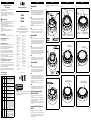
Montage SEK90
Bild 1
▸
Den Rotor des SEK90 vorsichtig unter Verwendung von 4 Anpress-
punkten auf die Motorwelle aufschieben, um die parallele Ausrich-
tung des Rotors und der Motorwelle zu gewährleisten. Bitte darauf
achten, dass die halbkreisförmigen Aussparungen am Flansch nicht
durch die Befestigungslaschen des Gebers verdeckt werden.
Bild 2
▸
Den Rotor sanft bis zum Anschlag herunterdrücken und die Schrau-
ben der Hohlwellenklemmung in der Reihenfolge der Nummerierung
(Schrauben 1 bis 6) mit einem Anzugsmoment von 0,4 Nm anziehen.
In einem zweiten Arbeitschritt sind die Schrauben in der umge-
kehrten Reihenfolge wie zuvor mit einem Anzugsmoment von 1 Nm
anzuziehen.
▸
Das Gehäuse drehen, bis es in den Zentrierbund einrastet.
Bild 3
▸
Das Gehäuse des SEK90 muss mit Schrauben am Flansch fixiert
werden. Das Anzugsmoment beträgt z. B. bei der Verwendung von
Schrauben M4 x 25 (nicht im Lieferumfang enthalten) ca. 2 Nm.
Montage SEK160
Bild 4
▸
Den Rotor des SEK160 vorsichtig unter Verwendung von 4 Anpress-
punkten auf die Motorwelle aufschieben, um die parallele Ausrich-
tung des Rotors und der Motorwelle zu gewährleisten. Bitte darauf
achten, dass die halbkreisförmigen Aussparungen am Flansch nicht
durch die Befestigungslaschen des Gebers verdeckt werden.
Bild 5
▸
Den Rotor sanft bis zum Anschlag herunterdrücken und die Schrauben
der Hohlwellenklemmung in der Reihenfolge der Nummerierung
(Schrauben 1 bis 6) mit einem Anzugsmoment von 0,4 Nm anziehen.
In einem zweiten Arbeitschritt sind die Schrauben in der umgekehrten
Reihenfolge wie zuvor mit einem Anzugsmoment von 1 Nm anzuziehen.
▸
Das Gehäuse drehen, bis es in den Zentrierbund einrastet.
Bild 6
▸
Das Gehäuse des SEK160 muss mit Schrauben am Flansch fixiert
werden. Das Anzugsmoment beträgt z. B. bei der Verwendung von
Schrauben M4 x 25 (nicht im Lieferumfang enthalten) ca. 2 Nm.
Montage SEK260
Bild 7
▸
Den Rotor des SEK260 vorsichtig unter Verwendung von 4 Anpres-
spunkten auf die Motorwelle aufschieben, um die parallele Ausrich-
tung des Rotors und der Motorwelle zu gewährleisten. Bitte darauf
achten, dass die halbkreisförmigen Aussparungen am Flansch nicht
durch die Befestigungslaschen des Gebers verdeckt werden.
Bild 8
▸
Den Rotor sanft bis zum Anschlag herunterdrücken und die Schrau-
ben der Hohlwellenklemmung in der Reihenfolge der Nummerie-
rung (Schrauben 1 bis 12) mit einem Anzugsmoment von 0,4 Nm
anziehen. In einem zweiten Arbeitschritt sind die Schrauben in der
umgekehrten Reihenfolge wie zuvor mit einem Anzugsmoment von
1 Nm anzuziehen.
▸
Das Gehäuse drehen, bis es in den Zentrierbund einrastet.
Bild 9
▸
Das Gehäuse des SEK260 muss mit Schrauben am Flansch fixiert
werden. Das Anzugsmoment beträgt z. B. bei der Verwendung von
Schrauben M4 x 25 (nicht im Lieferumfang enthalten) ca. 2 Nm.
Elektrischer Anschluss SEK90,
SEK160 und SEK260
▸
2 Schrauben des Leitungsanschluss lösen und die Abdeckung
entfernen.
▸
Den Stecker des Litzensatzes (nicht im Lieferumfang enthalten) oder
der Leitung (nicht im Lieferumfang enthalten) spannungsfrei in die
Steckerbuchse des Gebers einrasten.
▸
Den Litzensatz oder die Leitung in die Zugentlastung einführen.
▸
Abschließend die Abdeckung des Leitungsanschluss mit den Schrau-
ben fixieren.
Demontage SEK90, SEK160 und
SEK260
▸
2 Schrauben des Leitungsanschluss lösen und die Abdeckung
entfernen.
▸
Den Stecker des Litzensatz bzw. der Leitung spannungsfrei aus der Ste-
ckerbuchse des Gebers ziehen und aus der Zugentlastung entfernen.
▸
Lösen der Befestigungsschrauben des Gebergehäuses und der
Hohlwellenklemmung.
▸
Geber kann entfernt werden. Geber am Gehäuse halten und von der
Welle abziehen.
Bild 1
Bild 2
Bild 3
DEUTSCH DEUTSCH
Bild 4
Anpresspunkte
Bohrung für
Befestigungsschrauben
Mo
torwelle
M4-Gewindebohrung
en für
Befestigungsschrauben
Halbkreisförmige
Aussparungen
Bild 5
1
6
4
3
2
5
Schrauben für
Hohlwellenklemmung
Passsti
ft
Hohlwellenklemmung
Bild 6
Befestigungsschrauben
(nicht im Lieferumfang enthalten)
Bild 7
Anpresspunkte
Bohrung für
Bef
estigungs-
schrauben
Motorwelle
M4-Gewindebohrungen für
Befestigungsschrauben
Halbkreisförmige
Aussparungen
Bild 8
1
12
10
8
6
4
2
11
9
7
5
3
Schrauben für
Hohlwellenklemmung
Passsti
ft
Hohlwellenklemmung
Bild 9
Befestigungsschrauben
(nicht im Lieferumfang enthalten)
SICK Motor-Feedback-Systeme
Betriebsanleitung
SICK Motor-Feedback-Systeme
SEK90
SEK160
SEK260
SICK STEGMANN GmbH
Postfach 1560 · D-78156 Donaueschingen
Dürrheimer Straße 36 · D-78166 Donaueschingen
Telefon: +49 (0) 771 80 70 · Telefax +49 (0) 771 80 71 00
www.sick.com · [email protected]
Irrtümer und Änderungen vorbehalten.
a
ACHTUNG!
PIN-Belegung nur für Standard-Motor-Feedback-Systeme gültig. Bei
kundenspezifischen Motor-Feedback-Systemen bitte entsprech-
endes Datenblatt verwenden.
8013609/132Z/2019-04-02 ∙ AB_07
BZ int48
Please find detailed addresses and further locations in all major industrial
nations at www.sick.com
Australia
Phone +61 (3) 9457 0600
Austria
Phone +43 (0) 2236 62288-0
Belgium/Luxembourg
Phone +32 (0) 2 466 55 66
Brazil
Phone +55 11 3215-4900
Canada
Phone +1 905.771.1444
Czech Republic
Phone +420 2 57 91 18 50
Chile
Phone +56 (2) 2274 7430
China
Phone +86 20 2882 3600
Denmark
Phone +45 45 82 64 00
Finland
Phone +358-9-25 15 800
France
Phone +33 1 64 62 35 00
Germany
Phone +49 (0) 2 11 53 01
Hong Kong
Phone +852 2153 6300
Hungary
Phone +36 1 371 2680
India
Phone +91-22-6119 8900
Israel
Phone +972-4-6881000
Italy
Phone +39 02 27 43 41
Japan
Phone +81 3 5309 2112
Malaysia
Phone +603-8080 7425
Mexico
Phone +52 (472) 748 9451
Netherlands
Phone +31 (0) 30 229 25 44
New Zealand
Phone +64 9 415 0459
Norway
Phone +47 67 81 50 00
Poland
Phone +48 22 539 41 00
Romania
Phone +40 356-17 11 20
Russia
Phone +7 495 283 09 90
Singapore
Phone +65 6744 3732
Slovakia
Phone +421 482 901 201
Slovenia
Phone +386 591 78849
South Africa
Phone +27 (0)11 472 3733
South Korea
Phone +82 2 786 6321
Spain
Phone +34 93 480 31 00
Sweden
Phone +46 10 110 10 00
Switzerland
Phone +41 41 619 29 39
Taiwan
Phone +886-2-2375-6288
Thailand
Phone +66 2 645 0009
Turkey
Phone +90 (216) 528 50 00
United Arab Emirates
Phone +971 (0) 4 88 65 878
United Kingdom
Phone +44 (0)17278 31121
USA
Phone +1 800.325.7425
Vietnam
Phone +65 6744 3732

ENGLISH
Motor feedback systems are measuring instruments produced in ac-
cordance with recognized industrial regulations.
▸
The installation of the motor feedback system is to be carried out
by trained personal with knowledge of electrical engineering and
precision engineering
▸
A motor feedback system must be used only for the purpose ap-
propriate to its design.
Safety advice
▸
Observe the professional safety regulations and accident prevention
regulations applicable to your country.
▸
Switch off the voltage for all devices/machines and systems affected
by the assembly.
▸
Impacts to the shaft must be avoided.
▸
Never make or undo electrical connections to the motor
feedback system when voltage is applied as this may result in
damage to the device.
▸
Never pull or push on the motor feedback system housing.
Preparation for tting
Degrease the drive shaft and shaft of the motor feedback system.
Tools/parts required
▸
Phillips head screwdriver
▸
Hexagon key No. 2
General advice
The more exact the centering for the motor feedback system, the
narrower the angle and shaft oset for assembly.
For devices with a cable outlet, the shielding/braided shield is
connected to the device housing.
From an EMC point of view, it is essential that the device housing or
the cable shielding are grounded, either via the housing of the mating
plug or by connecting the braided shield of the cable. The braided
screen should be connected over a large area.
The large surface of the encoder housing is connected to the motor
potential via the spigot.
To ensure trouble-free operation, it is imperative to ensure a clean
screen connection on both sides.
When mounting the encoder, press shaft clamp after making sure it is
parallel to motor shaft. Hand pressure might be needed, when toler-
ances are tight.
When dismounting the encoder, pull it by holding housing only.
PIN and wire allocation
SEK90, SEK160 and SEK260
PIN Signal Color of
wires
Explanation
1 U
S
Red Supply voltage to the encoder
The supply voltage range of the encoder is
between +7 V and +12 V. The recommended
supply voltage is +8 V.
2 +SIN White Process data channel
+SIN is a sine signal of 1 V
PP
with a static oset
of REFSIN
3 REFSIN Brown Process data channel
A +2.5 V static voltage which serves as the
reference voltage for +SIN
4 +COS Pink Process data channel
+COS is a cosine signal of 1 V
PP
with a static
oset of REFCOS
5 REFCOS Black Process data channel
A +2.5 V static voltage which serves as the
reference voltage for +COS
6 GND Blue Encoder ground connection
Electrically isolated from the housing. The volt-
age relating to GND is +U
s
.
7 Data+ Gray or
yellow
Parameter channel; positive data signal
The parameter channel is an asynchronous,
semiduplex interface which corresponds
physically to the EIA RS485 specication. The
encoder can request data for this using various
commands. User-specic data such as position
oset in EEPROM of the encoder can also be
saved for this channel.
8 Data– Green or
purple
Parameter channel; negative data signal
The parameter channel is an asynchronous,
semiduplex interface which corresponds
physically to the EIA RS485 specication. The
encoder can request data for this using various
commands. User-specic data such as position
oset in EEPROM of the encoder can also be
saved for this channel.
ENGLISHENGLISH
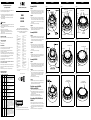
Assembly SEK90
Figure 1
▸
Carefully slide the SEK90 rotor onto the motor shaft, by using 4 fin-
ger points of pressure, to ensure parallelism between the encoder’s
rotor and motor’s shaft. Make sure that the semicircular notches on
the flange are not covered by the encoder's fastening lugs.
Figure 2
▸
Gently press the rotor down until it will go no further and tighten the
screws on the hollow shaft holder with a tightening torque of 0.4 in
the order in which they are numbered (screws 1 to 6). For the second
work step, tighten the screw in the opposite order with a tightening
torque of 1 Nm.
▸
Turn the housing until it clips into the spigot.
Figure 3
▸
The SEK90 housing must be attached to the flange using screws.
As an example, the tightening torque would be approx. 2 Nm when
using M4 x 25 screws (not included in delivery).
Assembly SEK160
Figure 4
▸
Carefully slide the SEK160 rotor onto the motor shaft, by using 4 fin-
ger points of pressure, to ensure parallelism between the encoder’s
rotor and motor’s shaft. Make sure that the semicircular notches on
the flange are not covered by the encoder's fastening lugs.
Figure 5
▸
Gently press the rotor down until it will go no further and tighten the
screws on the hollow shaft holder with a tightening torque of 0.4 in
the order in which they are numbered (screws 1 to 6). For the second
work step, tighten the screw in the opposite order with a tightening
torque of 1 Nm.
▸
Turn the housing until it clips into the spigot.
Figure 6
▸
The SEK160 housing must be attached to the flange using screws.
As an example, the tightening torque would be approx. 2 Nm when
using M4 x 25 screws (not included in delivery).
Assembly SEK260
Figure 7
▸
Carefully slide the SEK260 rotor onto the motor shaft, by using 4 fin-
ger points of pressure, to ensure parallelism between the encoder’s
rotor and motor’s shaft. Make sure that the semicircular notches on
the flange are not covered by the encoder's fastening lugs.
Figure 8
▸
Gently press the rotor down until it will go no further and tighten the
screws on the hollow shaft holder with a tightening torque of 0.4 Nm
in the order in which they are numbered (screws 1 to 12). For the
second work step, tighten the screw in the opposite order with a
tightening torque of 1 Nm.
▸
Turn the housing until it clips into the spigot.
Figure 9
▸
The SEK260 housing must be attached to the flange using screws.
As an example, the tightening torque would be approx. 2 Nm when
using M4 x 25 screws (not included in delivery).
Electrical connection SEK90,
SEK160 and SEK260
▸
Undo the two screws on the cable outlet and remove the cover.
▸
With the voltage supply disconnected, clip the plug of the braid set
(not included in delivery) or the cable (not included in delivery) into
the socket on the encoder.
▸
Feed the braid set or the cable into the cord grip.
▸
Finally, reattach the cable outlet cover using the screws.
Dismantling SEK90, SEK160 and
SEK260
▸
Undo the two screws on the cable outlet and remove the cover.
▸
With the voltage supply disconnected, pull the plug of the braid set or
the cable out of the encoder socket and remove from the cord grip.
▸
Undo the fastening screws on the encoder housing and the hollow
shaft holder.
▸
The encoder can be removed. Pull it by holding housing only.
Figure 1
Figure 2
Figure 3
ENGLISH ENGLISH
Figure 4
pressure points
mounting holes
mo
tor’s shaft
motor’s M4 thread hole
s
semi-circle area
Figure 5
1
6
4
3
2
5
shaft clamp screw
alignment
pin
shaft clamp
Figure 6
mounting screw
(not included in delivery)
Figure 7
pressure points
mounting
holes
motor’s shaft
motor M4
thread holes
semi-circle area
Figure 8
1
12
10
8
6
4
2
11
9
7
5
3
shaft clamp screws
alignment
pin
shaft clamp
Figure 9
mounting screw
(not included in delivery)
SICK Motor feedback systems
Operating instructions
SICK Motor feedback systems
SEK90
SEK160
SEK260
SICK STEGMANN GmbH
PO Box 1560 · D-78156 Donaueschingen, Germany
Dürrheimer Straße 36 · D-78166 Donaueschingen, Germany
Phone: +49 771 80 70 · Fax: +49 771 80 71 00
www.sick.com · [email protected]
a
Attention!
PIN allocation only valid for standard motor feedback systems.
For customer specific versions please see the relevant data sheet.
8013609/132Z/2019-04-02 ∙ AB_07
BZ int48
Australia
Phone +61 (3) 9457 0600
Austria
Phone +43 (0) 2236 62288-0
Belgium/Luxembourg
Phone +32 (0) 2 466 55 66
Brazil
Phone +55 11 3215-4900
Canada
Phone +1 905.771.1444
Czech Republic
Phone +420 2 57 91 18 50
Chile
Phone +56 (2) 2274 7430
China
Phone +86 20 2882 3600
Denmark
Phone +45 45 82 64 00
Finland
Phone +358-9-25 15 800
France
Phone +33 1 64 62 35 00
Germany
Phone +49 (0) 2 11 53 01
Hong Kong
Phone +852 2153 6300
Hungary
Phone +36 1 371 2680
India
Phone +91-22-6119 8900
Israel
Phone +972-4-6881000
Italy
Phone +39 02 27 43 41
Japan
Phone +81 3 5309 2112
Malaysia
Phone +603-8080 7425
Mexico
Phone +52 (472) 748 9451
Netherlands
Phone +31 (0) 30 229 25 44
New Zealand
Phone +64 9 415 0459
Norway
Phone +47 67 81 50 00
Poland
Phone +48 22 539 41 00
Romania
Phone +40 356-17 11 20
Russia
Phone +7 495 283 09 90
Singapore
Phone +65 6744 3732
Slovakia
Phone +421 482 901 201
Slovenia
Phone +386 591 78849
South Africa
Phone +27 (0)11 472 3733
South Korea
Phone +82 2 786 6321
Spain
Phone +34 93 480 31 00
Sweden
Phone +46 10 110 10 00
Switzerland
Phone +41 41 619 29 39
Taiwan
Phone +886-2-2375-6288
Thailand
Phone +66 2 645 0009
Turkey
Phone +90 (216) 528 50 00
United Arab Emirates
Phone +971 (0) 4 88 65 878
United Kingdom
Phone +44 (0)17278 31121
USA
Phone +1 800.325.7425
Vietnam
Phone +65 6744 3732
Subject to change without notice.
Please find detailed addresses and further locations in all major industrial
nations at www.sick.com
-
 1
1
-
 2
2


SICK SEK90, SEK160, SEK260 Motor feedback system rotary HIPERFACE® Bedienungsanleitung
- Typ
- Bedienungsanleitung
in anderen Sprachen
Verwandte Papiere
-
SICK SES/SEM70, SES/SEM90 Motor feedback system rotary HIPERFACE® Bedienungsanleitung
-
-
-
-
-
-
-
-
-