SICK SKS/SKM36 Motor feedback system rotary HIPERFACE® Bedienungsanleitung
- Typ
- Bedienungsanleitung

Sicherheitshinweise
Beachten Sie die für Ihr Land gültigen berufsgenossenschaftlichen
Sicherheits- und Unfallverhütungsvorschriften.
Schalten Sie die Spannung bei allen von der Montage betroffenen
Geräten/Maschinen und Anlagen ab.
Schläge und Stöße auf die Welle unbedingt vermeiden, kann zu
Kugellagerdefekt führen.
Für Stand Alone-Geber geeignete flexible Wellenkupplungen ver-
wenden. Die Eignung der Kupplung ist abhängig vom auftretenden
Winkel- und Wellenversatz, der Beschleunigung, Temperatur,
Drehzahl und von der im Motorfeedback-System-Datenblatt
angegebenen zulässigen Lagerbelastung für das Motorfeedback-
System.
Elektrische Verbindungen zum Motorfeedback-System nie bei ein-
geschalteter Spannung herstellen bzw. lösen, kann sonst zu
einem Gerätedefekt führen.
Das Wellenende des Motors darf beim SKS36/SKM36 mit Konus-
welle maximal einen Durchmesser von 12 mm haben
.
Anbauvorbereitung
Die Antriebswelle und Welle des Motorfeedback-Systems entfetten.
Erforderliche Werkzeuge/Teile
SKS36/SKM36 STAND ALONE
Für die Montage über die flanschseitigen Gewindebohrungen werden
Schrauben M4 benötigt.
Länge sowie Schraubenkopfausführung richten sich nach den
Einbauverhältnissen. Für die Befestigung über die Servonut werden
Servoklammern und Schrauben M3 benötigt; Schraubenlänge ent-
sprechend Einbauverhältnissen wählen.
SKS36/SKM36 mit Konuswelle
Für die Montage bzw. Demontage wird das Montagewerkzeug
BEF-MW-SKX36 benötigt.
Allgemein gültige Hinweise
Das Gehäuse ist mittels der Drehmomentabstützung für das
Motorfeedback-System verdrehfest mit der kundenseitigen
Anflanschung zu verbinden.
Je genauer die Zentrierung für das Motorfeedback-System ist, desto
geringer sind Winkel und Wellenversatz bei der Montage und um so
weniger werden die Lager des Motorfeedback-Systems belastet.
Es ist unter EMV-Gesichtspunkten zwingend notwendig, dass das
Gehäuse bzw. der Geber an Erde angeschlossen wird. Beim SKS36/
SKM36 mit Konuswelle wird dies über die Drehmomentenstütze
sichergestellt.
Bei Stand-Alone-Motorfeedback-Systemen mit Steckerabgang am
Gerätegehäuse ist das Steckergehäuse elektrisch leitend mit dem
Gerätegehäuse verbunden, während bei Geräten mit Kabelabgang
die Schirmung bzw. das Schirmgeflecht mit dem Gerätegehäuse ver-
bunden ist.
Es ist unter EMV-Gesichtspunkten zwingend notwendig, dass das
Gerätegehäuse bzw. der Kabelschirm an Erde angeschlossen wird.
Dies kann geschehen über das Gehäuse des Gegensteckers bzw.
durch Anschließen des Schirmgeflechts des Kabels. Das
Schirmgeflecht sollte großflächig angeschlossen werden.
Für einen störungsfreien Betrieb is t unbedingt auf eine saubere,
beidseitig aufgelegte Schirmanbindung zu achten.
DEUTSCH
SICK Motor-Feedback-Systeme
Betriebsanleitung
!
SICK Motor
-Feedback-Systeme
SKS36, SKM36
SKS36 STAND ALONE
SKM36 STAND ALONE
SICK STEGMANN GmbH
Postfach 1560 · D-78156 Donaueschingen
Dürrheimer Straße 36 · D-78166 Donaueschingen
Telefon: +49 (0) 771 80 70 · Telefax +49 (0) 771 80 71 00
www.sick.com · [email protected]
irrtümer und Änderungen vorbehalten
DEUTSCH
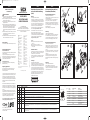
Motorfeedback-System mit Konus-
welle und Federblechabstützung
(Abb. 1)
Montage
Kundenseitige Antriebswelle blockieren.
Der Sechskant (1) der Geberwelle (2) muss in die Aussparung
der Befestigungsplatte (3) der Drehmomentenstütze (4) eingera-
stet sein. Das Montagewerkzeug (5) auf die Geberrückseite auf-
setzen und an den Ausschnitten des Gebergehäuses (6) einra-
sten. Den Geber mit Hilfe des am Montagewerkzeug (5) befind-
lichen Sechskants (7) in die Antriebswelle einschrauben.
Die Schrauben (8) dürfen nicht in die Befestigungslöcher des
Motors einhaken. Anzugsmoment: 4 Nm + 0,8 Nm.
Die Antriebswelle lösen und den Geber so drehen, bis die
Bohrungen in der Befestigungsplatte (3) über den
Befestigungslöchern des Motors liegen. Die Befestigungsplatte
(3) mit 2 Schrauben M3 (8) am Motorlagerschild abwechselnd
anziehen. Hierdurch wird die Geberwelle freigegeben.
Anzugsmoment: O,8 Nm ± 0,08 Nm.
Achtung!
Das Innengewinde in der Motorwelle muss schmutz- und
gratfrei sein.
Der Konus muss schmutz- und fettfrei sein.
Max. Drehmoment für das Gewinde, bevor der Konus
aufliegt: 0,8 Nm.
Elektrischer Anschluss
Die Abdeckung (12) ggf. mit Hilfe eines Schraubendrehers öffnen
(Bild A). Den Stecker (9) des Litzensatzes (10) spannungsfrei in
die Steckerbuchse (11) des Gebers einrasten.
Schließen (in die Aussparung des Gebergehäuses (6) einrasten
lassen). Das Einrasten muss durch Klicken deutlich spürbar
bzw. hörbar sein.
Demontage
Kundenseitige Antriebswelle blockieren.
Die Abdeckung (12) ggf. mit Hilfe eines Schraubendrehers öff-
nen. (Bild A). Den Litzensatz (9+10) spannungsfrei herausziehen.
Die 2 Schrauben M3 (8) entfernen. Die Befestigungsplatte (3) so
positionieren, dass die Schraubenlöcher mit der Drehmoment-
stütze (4) übereinstimmen. Bis zum Einrasten der Befestigungs-
platte (3) den Geber von Hand drehen. Das Montagewerkzeug (5)
auf die Geberrückseite aufsetzen und an den Ausschnitten des
Gebergehäuses (6) einrasten. Den Geber mit Hilfe des am
Montagewerkzeug (5) befindlichen Sechskants (7) von der
Antriebswelle lösen und entfernen.
DEUTSCH
Motorfeedback-System mit Ser vo-/
Klemmflansch (Stand-Alone)
Montage mit Montageplatte (Abb. 2)
Kundenseitige Antriebswelle blockieren.
Kupplung (5) am Geber (1) montieren. Darauf achten, dass diese
nicht am Geberflansch streift.
Geber mit 3 Schrauben M4 (3) z. B. an der Montageplatte (2)
befestigen. Geber (1) mit montierter Kupplung (5) und
Montageplatte (2) auf Antriebswelle und Zentrier-/Klemmansatz
aufschieben. Anschließend den Geber (1) über 4 Schrauben (4)
befestigen. Schrauben gegen Lösen sichern. Kupplung (5) auf der
Antriebswelle befestigen.
Elektrische Verbindung spannungsfrei herstellen.
Demontage
Kundenseitige Antriebswelle blockieren.
Elektrische Verbindung spannungsfrei trennen. Kupplung (5) auf
der Antriebswelle lösen. Die 4 Schrauben (4) lösen und den
Geber entfernen. Die Befestigungsplatte (2) durch Lösen der 3
Schrauben (3) sowie die Kupplung (5) vom Geber entfernen.
Montage mit Servoklammern (Abb. 3)
Kundenseitige Antriebswelle blockieren.
Kupplung (2) am Geber (1) montieren. Darauf achten, dass die
Kupplung (2) nicht am Geberflansch streift. Geber (1) mit mon-
tierter Kupplung (2) auf Antriebswelle und Zentrieransatz auf-
schieben.
Servoklammern (3) mit Schrauben M3 (4) montieren. Schrauben
(4) nur leicht festziehen, so dass der Geber (1) noch verdreht
werden kann.
Die Steckerposition durch Drehen am Gehäuse festlegen.
Schrauben (4) gegen Lösen sichern. Kupplung (2) auf der
Antriebswelle befestigen. Elektrische Verbindung spannungsfrei
herstellen.
Demontage
Kundenseitige Antriebswelle blockieren.
Elektrische Verbindung spannungsfrei trennen.
Servoklammern (3) durch Lösen der Schrauben (4) entfernen.
Kupplung (2) auf der Antriebswelle lösen und Zentrieransatz
trennen. Geber (1) abnehmen.
PIN- und Adernbelegung SKS36/SKM36
PIN Signal Kabelfarben Beschreibung
(Kabelabgang)
1U
s
rot Versorgungsspannung des Gebers. Der Betriebsspannungsbereich am Geber liegt zwischen + 7 V und + 12 V. Die empfohlene Versorgungsspannung ist + 8 V.
2 + SIN weiß Prozessdatenkanal; + SIN ist ein Sinussignal von 1 V
pp
mit einem statischen Offset von REFSIN.
3 REFSIN braun Prozessdatenkanal; eine + 2.5 V statische Spannung, die als Referenzspannung für + SIN dient.
4 + COS rosa Prozessdatenkanal; +COS ist ein Cosinussignal von 1 V
pp
mit einem statischen Offset von REFCOS.
5 REFCOS schwarz Prozessdatenkanal; eine + 2.5 V statische Spannung, die als Referenzspannung für + COS dient.
6 GND blau Masseanschluss des Gebers; galvanisch getrennt vom Gehäuse. Die zu GND bezogene Spannung ist + U
s
.
7 Daten + grau oder gelb Parameterkanal; positives Datensignal. Der Parameterkanal ist eine asynchrone, halbduplex Schnittstelle, die physikalisch der EIA RS485-Spezifikation entspricht.
Hierfür können durch verschiedene Befehle Daten vom Geber angefordert werden sowie anwenderspezifische Daten wie z. B. Positionsoffset im EEPROM des Gebers
abgespeichert werden.
8 Daten – grün oder violett Parameterkanal; negatives Datensignal. Der Parameterkanal ist eine asynchrone, halbduplex Schnittstelle, die physikalisch der EIA RS485-Spezifikation entspricht.
Hierfür können durch verschiedene Befehle Daten vom Geber angefordert werden sowie anwenderspezifische Daten wie z. B. Positionsoffset im EEPROM des Gebers
abgespeichert werden.
13
11
8
4
1
2
3
6
12
10
7
5
9
Demontage (Bild A)
Abb. 1
PIN- und Aderbelegung SKS36 STAND ALONE/SKM36 STAND ALONE
PIN Signal Farbe der Adern Erklärung
1 REFSIN braun Prozessdatenkanal
2 + SIN weiß Prozessdatenkanal
3 REFCOS schwarz Prozessdatenkanal
4 + COS rosa Prozessdatenkanal
5 Daten + grau oder gelb RS-485-Parameterkanal
6 Daten – grün oder violett RS-485-Parameterkanal
7 GND blau Masseanschluss
8 +U
s
rot Encoder-Versorgungsspannung
Schirm Gehäusepotenzial
12
3
45 6
7
8
8-polig-A-codiert
5
Ansicht Steckseite
5
2
3
3
4
4
1
Abb. 2
2
3
4
4
3
3
4
1
Abb. 3
For use in NFPA 79 applications only.
Interconnection cables and accessories are
available from SICK.
MA_SKS-M36:MA_SKS/M36 22.03.2011 10:25 Uhr Seite 1
8013452/13AP/2019-03-27 · AB_07
BZ int48
Please find detailed addresses and further locations in all major industrial
nations at www.sick.com
Australia
Phone +61 (3) 9457 0600
Austria
Phone +43 (0) 2236 62288-0
Belgium/Luxembourg
Phone +32 (0) 2 466 55 66
Brazil
Phone +55 11 3215-4900
Canada
Phone +1 905.771.1444
Czech Republic
Phone +420 2 57 91 18 50
Chile
Phone +56 (2) 2274 7430
China
Phone +86 20 2882 3600
Denmark
Phone +45 45 82 64 00
Finland
Phone +358-9-25 15 800
France
Phone +33 1 64 62 35 00
Germany
Phone +49 (0) 2 11 53 01
Hong Kong
Phone +852 2153 6300
Hungary
Phone +36 1 371 2680
India
Phone +91-22-6119 8900
Israel
Phone +972-4-6881000
Italy
Phone +39 02 27 43 41
Japan
Phone +81 3 5309 2112
Malaysia
Phone +603-8080 7425
Mexico
Phone +52 (472) 748 9451
Netherlands
Phone +31 (0) 30 229 25 44
New Zealand
Phone +64 9 415 0459
Norway
Phone +47 67 81 50 00
Poland
Phone +48 22 539 41 00
Romania
Phone +40 356-17 11 20
Russia
Phone +7 495 283 09 90
Singapore
Phone +65 6744 3732
Slovakia
Phone +421 482 901 201
Slovenia
Phone +386 591 78849
South Africa
Phone +27 (0)11 472 3733
South Korea
Phone +82 2 786 6321
Spain
Phone +34 93 480 31 00
Sweden
Phone +46 10 110 10 00
Switzerland
Phone +41 41 619 29 39
Taiwan
Phone +886-2-2375-6288
Thailand
Phone +66 2 645 0009
Turkey
Phone +90 (216) 528 50 00
United Arab Emirates
Phone +971 (0) 4 88 65 878
United Kingdom
Phone +44 (0)17278 31121
USA
Phone +1 800.325.7425
Vietnam
Phone +65 6744 3732
C
U
L
US
®

Safety Notes
Observe the professional safety regulations and accident preven-
tion regulations applicable to your country.
Switch off the voltage for all devices/machines and systems affec-
ted by the assembly.
Impacts and shocks to the shaft MUST be avoided, as this may
lead to damage to the ball bearings.
Use suitable flexible shaft couplings for stand alone encoders. The
suitability of the coupling depends on the occurring angle and
shaft offset, acceleration, temperature, speed and bearing load
permitted for the motor feedback system, as stipulated by the
motor feedback system datasheet.
Never make or undo electrical connections to the motor feedback
system when voltage is applied, otherwise this may result in
damage to the devices.
For SKS36/SKM36 encoders with tapered shaft the shaft end of
the motor may only have a diameter of 12 mm max..
Preparation for Attachment
Degrease the drive shaft and the shaft of the motor feedback
system.
Tools/Parts Required
SKS36/SKM36 STANDALONE
Mounting using the threaded flange holes requires M4 screws.
The length as well as the screw head type will depend on the fitting
conditions. Fixing via the servo groove requires servo clamps and M3
screws; select the screw length according to the fitting conditions.
SKS36/SKM36 with tapered shaft
For the mounting resp. demounting the assembly tool BEF-MW-
SKX36 is required.
Generally Applicable No tes
Using the torque support for the motor feedback system, the housing
must be correctly seated in the customer‘s flange arrangement.
The more precise the centring for the motor feedback system, the
less the angle and shaft offset during assembly and the less load on
the bearings of the motor feedback system.
EMC considerations make it mandatory to connect the housing and
the encoder, resp., to earth. For the SKS36/SKM36 with tapered
shaft, this is provided by the torque support.
For standalone motor feedback systems with a connector exit, the
connector housing is connected to the device housing so as to be
electrically conductive while, for devices with outgoing cable, the
screening and the woven screen, resp., will be connected to the
device housing.
EMC considerations make it mandatory to connect the device hou-
sing and the cable screen, resp., to earth. This may be effected via
the housing of the mating connector and by connecting the braided
screen of the cable, resp. The braided screen should be connected
over a large area.
To ensure trouble-free operation, it is imperative to ensure a clean
screen connection on both sides.
ENGLISH
SICK Motor feedback systems
Operating instructions
!
SICK Motor feedback systems
SKS36, SKM36
SKS36 STANDALONE
SKM36 STANDALONE
SICK STEGMANN GmbH
PO Box 1560 · D-78156 Donaueschingen, Germany
Dürrheimer Straße 36 · D-78166 Donaueschingen,
Germany Phone: +49 771 80 70 · Fax: +49 771 80 71 00
www.sick.com · [email protected]
Subject to change without notice
ENGLISH
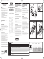
Motor Feedback System with
Tapered Shaft and Spring Mounting
Support (Fig. 1)
Assembly
Block customer‘s drive shaft to prevent rotation.
The hexagonal part (1) of the encoder shaft (2) must be engaged
in the recess of the fixing plate (3) of the torque support (4).
Place the assembly tool (5) on the back of the encoder and enga-
ge on the cut-outs of the encoder housing (6). Using the hexago-
nal part (7) of the assembly tool (5), screw the encoder into the
drive shaft.
Screws (8) must not hook into the fixing holes of the motor.
Tightening torque: 4 Nm + 0,8 Nm.
Release the drive shaft and rotate the encoder until the holes in
the fixing plate (3) are positioned over the fixing holes of the
motor flange. Alternately tighten the fixing plate (3) with 2 M3
screws (8) on the motor flange. This releases the encoder shaft.
Tightening torque: O,8 Nm ± 0,08 Nm.
Attention!
The internal thread in the motor shaft must be free from burrs
and dirt.
The taper must be free of dirt and grease.
Max. torque for the thread, before the taper is seated: 0,8 Nm.
Electrical connection
If neccessary please open the cover (12) with a screwdriver (Fig.
A). Engage the connector (9) fitted with the set of strands(10),
volt-free, in the connector socket (11) of the encoder. Close the
cover (12) (engage in the recess of the encoder housing). The
engagement by clicking must be clearly felt or heard.
Disassembly
Block customer’s drive shaft to prevent rotation.
If neccessary please open the cover (12) with a screwdriver
(Fig. A). Remove the connector fitted with the set of strands
(9+10) volt-free. Remove the 2 M3 screws (8). The fixing plate (3)
is to be positioned in such a way that the screw holes are aligned
with the stator coupling (4). Turn the encoder by hand until fixing
plate engages. Place the assembly tool (5) on the back of the
encoder and engage in the recesses of the encoder housing (6).
Using the hexagonal part (7) of the assembly tool (5), detach and
remove the encoder from drive shaft.
ENGLISH
Motor Feedback System with
Ser vo-/Face Mount Flange
(Standalone)
Assembly with mounting plate (Fig. 2)
Block customer’s drive shaft to prevent rotation.
Mount coupling (5) onto the encoder (1). Ensure that it does not
brush against the encoder flange.
Fit the encoder with 3 M4 screws (3), e.g. on the mounting plate
(2). Push encoder (1) with mounted coupling (5) and mounting
plate (2) onto drive shaft and centring/clamping neck.
Then fix the encoder (1) via 4 screws (4). Secure the screws
against loosening. Fix coupling (5) onto the drive shaft.
Screw on connector volt-free and connect strands of the
outgoing lead (volt-free), resp.
Disassembly
Block customer’s drive shaft to prevent rotation.
Undo electrical connection volt-free. Loosen coupling (5) on the
drive shaft. Undo the 4 screws (4) and remove the encoder.
Remove the fixing plate (2) by undoing the 3 screws (3) and also
remove the coupling (5) from the encoder.
Assembly with servo clamps (Fig. 3)
Block customer’s drive shaft to prevent rotation.
Mount coupling (2) on the encoder (1). Ensure that the coupling
(2) does not brush against the encoder flange. Push encoder (1)
with mounted coupling (2) onto the drive shaft and centring neck.
Mount servo clamps (3) with M3 screws (4). Tighten screws (4)
only lightly such that the encoder (1) can still be rotated.
Determine the connector position by rotating the housing. Fully
tighten to prevent screws (4) from working loose. Fix coupling (2)
onto the drive shaft.
Screw on connector volt-free and connect strands of the
outgoing lead (volt-free), resp.
Disassembly
Block customer’s drive shaft to prevent rotation.
Undo electrical connection volt-free. Remove servo clamps (3) by
undoing the screws (4). Loosen coupling (2) on the drive shaft
and detach centring neck. Remove encoder (1).
PIN and wire allocation SKS36/SKM36
PIN Signal Cable coulours Description
(Cable outlet)
1U
s
red Encoder supply voltage. The operating voltage at the encoder ranges from + 7 V to + 12 V. The recommended supply voltage is + 8 V.
2 + SIN white Process data channel; + SIN is a sine signal of 1 V
pp
with a static offset of REFSIN.
3 REFSIN brown Process data channel; a static voltage of + 2.5 V, which serves as reference voltage for + SIN.
4 + COS pink Process data channel; + COS is a cosine signal of 1 V
pp
with a static offset of REFCOS.
5 REFCOS black Process data channel; a static voltage of + 2.5 V, which serves as reference voltage for + COS.
6 GND blue Encoder ground connection; galvanically separated from the housing. The voltage relating to GND is + U
s
.
7 Data + grey or yellow Parameter channel; positive data signal. The parameter channel is an asynchronous, half-duplex interface, which physically corresponds to the EIA RS485 specification.
For this, data can be requested from the encoder through different commands; this also makes it possible to write user-specific data such as position offset to the
EEPROM of the encoder.
8 Data – green or purple Parameter channel; negative data signal. The parameter channel is an asynchronous, half-duplex interface, which physically corresponds to the EIA RS485 specification.
For this, data can be requested from the encoder through different commands; this also makes it possible to write user-specific data such as position offset to the
EEPROM of the encoder.
13
11
8
4
1
2
3
6
12
10
7
5
9
Disassembly (Fig. A)
5
2
3
3
4
4
1
Fig. 1
Fig. 2
PIN and wire allocation SKS36 STANDALONE/SKM36 STANDALONE
PIN Signal Colour of wires Explanation
1 REFSIN brown Process data channel
2 + SIN white Process data channel
3 REFCOS black Process data channel
4 + COS pink Process data channel
5 Daten + grey or yellow RS-485 Parameter channel
6 Daten – green or purple RS-485 Parameter channel
7 GND blue Ground connection
8 +U
s
red Encoder Supply voltage
Screen Housing potential
View of the plug-in face
2
3
4
4
3
3
4
1
Fig. 3
12
3
45 6
7
8
8-pin A coded
5
For use in NFPA 79 applications only.
Interconnection cables and accessories
are available from Sick.
C US
U
L
®
MA_SKS-M36:MA_SKS/M36 22.03.2011 10:25 Uhr Seite 2
8013452/13AP/2019-03-27 · AB_07
BZ int48
Please find detailed addresses and further locations in all major industrial
nations at www.sick.com
Australia
Phone +61 (3) 9457 0600
Austria
Phone +43 (0) 2236 62288-0
Belgium/Luxembourg
Phone +32 (0) 2 466 55 66
Brazil
Phone +55 11 3215-4900
Canada
Phone +1 905.771.1444
Czech Republic
Phone +420 2 57 91 18 50
Chile
Phone +56 (2) 2274 7430
China
Phone +86 20 2882 3600
Denmark
Phone +45 45 82 64 00
Finland
Phone +358-9-25 15 800
France
Phone +33 1 64 62 35 00
Germany
Phone +49 (0) 2 11 53 01
Hong Kong
Phone +852 2153 6300
Hungary
Phone +36 1 371 2680
India
Phone +91-22-6119 8900
Israel
Phone +972-4-6881000
Italy
Phone +39 02 27 43 41
Japan
Phone +81 3 5309 2112
Malaysia
Phone +603-8080 7425
Mexico
Phone +52 (472) 748 9451
Netherlands
Phone +31 (0) 30 229 25 44
New Zealand
Phone +64 9 415 0459
Norway
Phone +47 67 81 50 00
Poland
Phone +48 22 539 41 00
Romania
Phone +40 356-17 11 20
Russia
Phone +7 495 283 09 90
Singapore
Phone +65 6744 3732
Slovakia
Phone +421 482 901 201
Slovenia
Phone +386 591 78849
South Africa
Phone +27 (0)11 472 3733
South Korea
Phone +82 2 786 6321
Spain
Phone +34 93 480 31 00
Sweden
Phone +46 10 110 10 00
Switzerland
Phone +41 41 619 29 39
Taiwan
Phone +886-2-2375-6288
Thailand
Phone +66 2 645 0009
Turkey
Phone +90 (216) 528 50 00
United Arab Emirates
Phone +971 (0) 4 88 65 878
United Kingdom
Phone +44 (0)17278 31121
USA
Phone +1 800.325.7425
Vietnam
Phone +65 6744 3732
-
 1
1
-
 2
2


SICK SKS/SKM36 Motor feedback system rotary HIPERFACE® Bedienungsanleitung
- Typ
- Bedienungsanleitung
in anderen Sprachen
Verwandte Papiere
-
SICK SEK37, SEL37 AXIAL CONNECTOR Motor feedback system rotary HIPERFACE® Bedienungsanleitung
-
-
-
-
-
-
-
-
-