SICK SEK34, SEL34 Motor feedback system rotary HIPERFACE® Bedienungsanleitung
- Typ
- Bedienungsanleitung

DEUTSCH
SICK Motor-Feedback-Systeme sind nach den anerkann ten Regeln der Technik
hergestellte Messgeräte.
aDer Anbau des Motor-Feedback-Systems ist von einem Fachmann mit Kennt-
nissen in Elektrik und Feinmechanik vorzunehmen.
aDas Motor-Feedback-System darf nur zu dem seiner Bauart entsprechenden
Zweck verwendet werden.
aSicherheitshinweise
▸
Beachten Sie die für Ihr Land gültigen berufsgenossenschaftlichen Sicher-
heits- und Unfallverhütungsvorschriften.
▸
Schalten Sie die Spannung bei allen von der Montage betroffenen Gerä-
ten / Maschinen und Anlagen ab.
▸
Schläge und Stöße auf die Welle unbedingt vermeiden.
▸
Elektrische Verbindungen zum Motor-Feedback-
System nie bei eingeschalteter Spannung herstellen bzw. lösen, kann sonst zu
einem Gerätedefekt führen.
▸
Niemals am Motor-Feedback-System-Gehäuse ziehen bzw. drücken.
Anbauvorbereitung
Die Antriebswelle und Welle des Motor-Feedback-Systems entfetten.
Erforderliche Werkzeuge / Teile
Torx-Werkzeug T10
Allgemein gültige Hinweise
Je genauer die Zentrierung für das Motor-Feedback-System ist, desto geringer
sind Winkel und Wellenversatz bei der Montage und um so weniger werden die
Kupplung und die Lager des Motor-Feedback-Systems belastet.
Es ist unter EMV-Gesichtspunkten zwingend notwendig, dass das Gerätegehäuse
bzw. der Leitungsschirm an Erde angeschlossen wird. Dies kann geschehen über
das Gehäuse des Gegensteckers bzw. durch Anschließen des Schirmgeechts
der Leitung. Das Schirmgeecht sollte großächig angeschlossen werden.
Für einen störungsfreien Betrieb ist unbedingt auf eine saubere, beidseitig
aufgelegte Schirmanbindung zu achten.
SICK Motor-Feedback-Systeme
Betriebsanleitung
DEUTSCH
SICK Motor-Feedback-Systeme
SEK34, SEL34
SICK STEGMANN GmbH
Postfach 1560 · D-78156 Donaueschingen
Dürrheimer Straße 36 · D-78166 Donaueschingen
Telefon: +49 (0) 771 80 70 · Telefax +49 (0) 771 80 71 00
www.sick.com · [email protected]
Australia
Phone +61 (3) 9457 0600
Austria
Phone +43 (0) 2236 62288-0
Belgium/Luxembourg
Phone +32 (0) 2 466 55 66
Brazil
Phone +55 11 3215-4900
Canada
Phone +1 905.771.1444
Czech Republic
Phone +420 2 57 91 18 50
Chile
Phone +56 (2) 2274 7430
China
Phone +86 20 2882 3600
Denmark
Phone +45 45 82 64 00
Finland
Phone +358-9-25 15 800
France
Phone +33 1 64 62 35 00
Germany
Phone +49 (0) 2 11 53 01
Hong Kong
Phone +852 2153 6300
Hungary
Phone +36 1 371 2680
India
Phone +91-22-6119 8900
Israel
Phone +972-4-6881000
Italy
Phone +39 02 27 43 41
Japan
Phone +81 3 5309 2112
Malaysia
Phone +603-8080 7425
Mexico
Phone +52 (472) 748 9451
Netherlands
Phone +31 (0) 30 229 25 44
New Zealand
Phone +64 9 415 0459
Norway
Phone +47 67 81 50 00
Poland
Phone +48 22 539 41 00
Romania
Phone +40 356-17 11 20
Russia
Phone +7 495 283 09 90
Singapore
Phone +65 6744 3732
Slovakia
Phone +421 482 901 201
Slovenia
Phone +386 591 78849
South Africa
Phone +27 (0)11 472 3733
South Korea
Phone +82 2 786 6321
Spain
Phone +34 93 480 31 00
Sweden
Phone +46 10 110 10 00
Switzerland
Phone +41 41 619 29 39
Taiwan
Phone +886-2-2375-6288
Thailand
Phone +66 2 645 0009
Turkey
Phone +90 (216) 528 50 00
United Arab Emirates
Phone +971 (0) 4 88 65 878
United Kingdom
Phone +44 (0)17278 31121
USA
Phone +1 800.325.7425
Vietnam
Phone +65 6744 3732
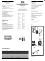
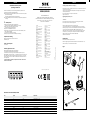
Klemmung der Federelemente durch
Motorabdeckung (Abb. 1)
Kundenseitige Antriebswelle blockieren. Geber (1) vorsichtig auf die Motorwelle
schieben. Darauf achten, dass der innere oder äußere Zentrierbund des Gebers
(7) sauber in der Zentrierung des Motors (2) anliegt und die Konuswelle (6)
gerade in den Konus der Motorwelle eingeführt wird.
Die Konus-Befestigungsschraube (3) anziehen:
Anzugmoment 2,2 Nm ± 5 %.
aACHTUNG!
▸
Das Innengewinde in der Motorwelle muss schmutz-, fett- und gratfrei sein.
▸
Der Konus muss schmutz- und fettfrei sein.
Den Stecker (11) des Litzensatzes (12) spannungsfrei in die seitliche Stecker-
buchse (8) des Gebers einrasten. Bei der Verwendung dieses Gebertyps muss
auf eine ausreichende Zugentlastung geachtet werden. Schirmanschluss (10)
anschließen.
Den Geber, wie im Maßbild des SEK34 / SEL34 in der Produktinformation
(8014799) beschrieben, über die Federelemente des Deckels (9) mit der Mo-
torabdeckung (4) klemmen.
Kundenseitige Antriebswelle freigeben.
Demontage
Kundenseitige Antriebswelle blockieren. Motorab deckung önen.
Elektrische Verbindung (8 + 11) spannungsfrei trennen.
Konus-Befestigungschraube (3) lösen und entfernen.
Klemmung der Federelemente durch
Motorabdeckung
Abb. 1
2
1
3
4
10
9
8
6
7
11
12
PIN- und Adernbelegung SEK34 / SEL34
PIN Signal Farbe der Adern Erklärung
1
U
s
rot 7 ... 12 V Versorgungsspannung
2
+ SIN
weiß Prozessdatenkabel
3
REFSIN
braun Prozessdatenkabel
4
+ COS
rosa Prozessdatenkabel
5
REFCOS
schwarz Prozessdatenkabel
6
GND
blau Masseanschluss
7
Daten +
grau oder gelb RS-485-Parameterkabel
8
Daten -
grün oder violett RS-485-Parameterkabel
Der GND-(0 V) Anschluss der Versorgungsspannung hat keine Verbindung zum Gehäuse.
8014728/132Z/2019-04-02 ∙ AB_07
BZ int48
Irrtümer und Änderungen vorbehalten.

ENGLISH
SICK motor feedback systems are measuring instruments produced in Ac-
cordance with recognized indus trial regulations.
aThe installation of the motor feedback system is to be carried out by trained
personal with knowledge
of electrical engineering and precision engineering.
aA motor feedback system must be used only for the purpose appropriate to
its design.
aSafety advice
▸
Observe the professional safety regulations and
accident prevention regulations applicable to your country.
▸
Switch off the voltage for all devices / machines
and systems affected by the assembly.
▸
Impacts to the shaft MUST be avoided.
▸
Never make or undo electrical connections to the motor feedback system
when voltage is applied as
this may result in damage to the device.
▸
Never pull or push on the motor feedback system housing.
Preparation for tting
Degrease the drive shaft and shaft of the motor
feedback system.
Tools / parts required
Torx tool T10
Generally applicable notes
Mounting angles and shaft oset during assembly
can introduce inaccuracy. Maximum performance
is achieved when the centering of the motor feedback system is precise.
Regarding EMC, the device housing, i. e. the cable screen must be connected to
earth. This can be achieved via the housing of the mating plug, i. e. by connec-
ting the braided screen of the cable. The braided screen should be connected
over a large area.
To ensure trouble-free operation, it is imperative to ensure a clean screen
connection on both sides.
SICK Motor feedback systems
Operating instructions
ENGLISH
SICK Motor feedback systems
SEK34, SEL34
SICK STEGMANN GmbH
PO Box 1560 · D-78156 Donaueschingen, Germany
Dürrheimer Straße 36 · D-78166 Donaueschingen, Germany
Phone: +49 771 80 70 · Fax: +49 771 80 71 00
www.sick.com · [email protected]
Clamping of spring elements via cover (Fig. 1)
Block motor drive shaft. Carefully push encoder (1) onto motor shaft. Ensure that
the inner or outer centering
collar (7) of the encoder located cleanly with the center ing of the motor (2) and
that the tapered shaft (6)
is inserted straight into the taper of the motor shaft.
Tighten the screw (3):
Tightening torque: 2.2 Nm ± 5 %.
aCaution!
▸
The thread in the motor shaft must be free from dirt, grease and burrs.
▸
The taper must be free from dirt and grease.
With the supply voltage disconnect, push the plug (11)
of the stranded cable set (12), into the lateral plug socket (8) of the encoder.
When using this type of encoder a suitable method of strain relief must be used
to secure the stranded cable assembly. Make shielding connection (10).
Clamping of encoder via the motor cover (4), using the spring elements on the
encoder cover (9), according to the description in the dimension drawing for
SEK34 / SEL34 in the product information (8014800).
Unblock motor drive shaft.
Disassembly
Block motor drive shaft. Open motor cover.
With the supply voltage disconnected withdraw the stranded cable set (8 + 11).
Undo the screw (3). The encoder can be removed.
Fig. 1
Clamping of spring elements via cover
2
1
3
4
10
9
8
6
7
11
12
PIN and wire allocation SEK34 / SEL34
PIN Signal Color of wires Explanation
1
U
s
red Supply voltage 7 ... 12 V
2
+ SIN
white Process data channel
3
REFSIN
brown Process data channel
4
+ COS
pink Process data channel
5
REFCOS
black Process data channel
6
GND
blue Ground connection
7
Data +
grey or yellow RS-485-parameter channel
8
Data -
green or purple RS-485-parameter channel
The GND (0 V) connection of the supply voltage has no connection to the housing.
Australia
Phone +61 (3) 9457 0600
Austria
Phone +43 (0) 2236 62288-0
Belgium/Luxembourg
Phone +32 (0) 2 466 55 66
Brazil
Phone +55 11 3215-4900
Canada
Phone +1 905.771.1444
Czech Republic
Phone +420 2 57 91 18 50
Chile
Phone +56 (2) 2274 7430
China
Phone +86 20 2882 3600
Denmark
Phone +45 45 82 64 00
Finland
Phone +358-9-25 15 800
France
Phone +33 1 64 62 35 00
Germany
Phone +49 (0) 2 11 53 01
Hong Kong
Phone +852 2153 6300
Hungary
Phone +36 1 371 2680
India
Phone +91-22-6119 8900
Israel
Phone +972-4-6881000
Italy
Phone +39 02 27 43 41
Japan
Phone +81 3 5309 2112
Malaysia
Phone +603-8080 7425
Mexico
Phone +52 (472) 748 9451
Netherlands
Phone +31 (0) 30 229 25 44
New Zealand
Phone +64 9 415 0459
Norway
Phone +47 67 81 50 00
Poland
Phone +48 22 539 41 00
Romania
Phone +40 356-17 11 20
Russia
Phone +7 495 283 09 90
Singapore
Phone +65 6744 3732
Slovakia
Phone +421 482 901 201
Slovenia
Phone +386 591 78849
South Africa
Phone +27 (0)11 472 3733
South Korea
Phone +82 2 786 6321
Spain
Phone +34 93 480 31 00
Sweden
Phone +46 10 110 10 00
Switzerland
Phone +41 41 619 29 39
Taiwan
Phone +886-2-2375-6288
Thailand
Phone +66 2 645 0009
Turkey
Phone +90 (216) 528 50 00
United Arab Emirates
Phone +971 (0) 4 88 65 878
United Kingdom
Phone +44 (0)17278 31121
USA
Phone +1 800.325.7425
Vietnam
Phone +65 6744 3732
8014728/132Z/2019-04-02 ∙ AB_07
BZ int48
Subject to change without notice.
-
 1
1
-
 2
2


SICK SEK34, SEL34 Motor feedback system rotary HIPERFACE® Bedienungsanleitung
- Typ
- Bedienungsanleitung
in anderen Sprachen
Verwandte Papiere
-
SICK SKS/SKM36 Motor feedback system rotary HIPERFACE® Bedienungsanleitung
-
-
-
-
-
-
-
-
-