SICK SES/SEM70, SES/SEM90 Motor feedback system rotary HIPERFACE® Bedienungsanleitung
- Typ
- Bedienungsanleitung

Betrie
bsan‐
leitung
D E U T S C H d e
1 Zu diesem Dokument
Bitte lesen Sie diese Betriebsanleitung sorgfältig, bevor Sie mit dem Motor-Feed‐
back-System SES/SEM70, SES/SEM90 arbeiten, es montieren, in Betrieb neh‐
men oder warten.
1.1 Funktion dieses Dokuments
Diese Betriebsanleitung leitet das technische Personal des Maschinenherstellers
bzw. Maschinenbetreibers zur Montage, Elektroinstallation, Inbetriebnahme sowie
zum Betrieb und zur Wartung des Motor-Feedback-Systems SES/SEM70 sowie
SES/SEM90 an.
1.2 Verwendete Symbole
WARNUNG
Ein Warnhinweis weist Sie auf konkrete oder potenzielle Gefahren hin. Dies
soll Sie vor Unfällen bewahren. Lesen und befolgen Sie Sicherheitshinweise
sorgfältig.
1.3 Zugehörige Dokumente
Schnittstellenhandbuch „HIPERFACE
®
“, Bestellnummer 8010701, Stand 02.2016
(oder neuer)
1.4 Wartung und Reparatur
Das Motor-Feedback-System SES/SEM70 sowie SES/SEM90 ist wartungsfrei. Bei
Defekt ist keine Reparaturmöglichkeit vorgesehen. Bitte kontaktieren Sie uns bei
Reklamationen. Mehrfache Montage/Demontage des Motor-Feedback-Systems
ist nicht vorgesehen.
1.5 Entsorgung
b
Entsorgen Sie unbrauchbare oder irreparable Geräte immer gemäß den
jeweils gültigen landesspezifischen Abfallbeseitigungsvorschriften.
HINWEIS
Gerne sind wir Ihnen bei der Entsorgung dieser Geräte behilflich. Sprechen
Sie uns an.
2 Produktbeschreibung
Geber der Typen SES/SEM70 sowie SES/SEM90 sind Motor-Feedback-Systeme,
die aufgrund ihrer Ausstattung zum dynamischen und präzisen Betrieb von Servo-
Regelkreisen prädestiniert sind.
Das Gesamtsystem, bestehend aus Geber, Auswertesystem, Servo-Umrichter und
Motor, bildet einen Regelkreis. Aus den Gebersignalen werden Ist-Werte für Kom‐
mutierung, Drehzahl, Drehrichtung und Lage abgeleitet.
Die Übermittlung der Sensorsignale zum Auswertesystem erfolgt über eine
HIPERFACE
®
-Schnittstelle.
WARNUNG
Das Motor-Feedback-System SES/SEM70 und SES/SEM90 ist kein Sicher‐
heitsbauteil.
3 Allgemein gültige Hinweise
Schalten Sie die Spannung bei allen von der Montage betroffenen Maschinen /
Anlagen ab.
Je genauer die Zentrierung für das Motor-Feedback-System ist, desto geringer
sind Winkel und Wellenversatz bei der Montage.
Es ist unter EMV-Gesichtspunkten zwingend notwendig, dass das Gehäuse bzw.
der Geber an Erde angeschlossen wird.
Beim SES/SEM70 und SES/SEM90 mit geschirmten Kabel (Artikel-Nr. 2089521)
wird dies über die integrierte Schirmleitung sichergestellt.
Beim SES/SEM70 und SES/SEM90 mit ungeschirmten Kabel (Artikel-Nr.
2031086) muss dies über das Gesamtsystem sichergestellt werden.
WARNUNG
Für einen störungsfreien Betrieb ist unbedingt auf eine geeignete Schirman‐
bindung des Motors zu achten.
Bei engen Toleranzen zwischen Motorwelle und Motor-Feedback-System kann das
Aufschieben des Rotors erschwert sein.
Bei der Demontage des Motor-Feedback-Systems muss das Motor-Feedback-Sys‐
tem am Gehäuse gehalten und anschließend von der Motorwelle abgezogen wer‐
den.
3.1 Anbauvorbereitung
b
Die Antriebswelle ggf. entfetten.
b
Auf Beschädigungen achten!
4 Motor-Feedback-System SES/SEM70
4.1 Erforderliche Werkzeuge/Teile
Für die Befestigung des Motor-Feedback-Systems werden 3 Stk. Zylinderkopf‐
schrauben M3 nach ISO 4762 (DIN 912) oder ähnliche Schraubentypen mit einer
Mindestfestigkeit von 8.8 benötigt. Schraubenlänge (mindestens 20mm) und
Schraubenkopfausführung sind entsprechend den Einbauverhältnissen zu wäh‐
len.
Für die Montage bzw. Demontage der Hohlwellenklemmung wird ein Innensechs‐
kantschlüssel SW2 benötigt.
4.2 Montage
b
Kundenseitige Antriebswelle blockieren.
b
Den Rotor des SES/SEM70 vorsichtig unter Verwendung von 4 Anpresspunk‐
ten auf die Motorwelle aufschieben, um die parallele Ausrichtung des Rotors
und der Motorwelle zu gewährleisten.
HINWEIS
Bitte darauf achten, dass der Zentrierbund des Motor-Feedback-Sys‐
tems nicht komplett in den Zentrierbund des Motorflansches einrastet.
b
Durch die Geometrie des Zentrierbundes mit den Ausprägungen auf der
Rückseite des Motor-Feedback-Systems entsteht ein definierter Spalt. Auf
diese Weise kann ohne ein Montagewerkzeug das Motor-Feedback-System
justiert werden.
b
Den Rotor sanft bis zum Anschlag herunterdrücken und die Schrauben der
Hohlwellenklemmung in der Reihenfolge der Nummerierung (Schrauben 1
bis 5) anziehen.
Anzugsmoment Schraube (Hohlwellenklemmung): 0,4 Nm.
b
In einem zweiten Arbeitsschritt sind die Schrauben in der umgekehrten Rei‐
henfolge wie zuvor anzuziehen.
Anzugsmoment Schraube (Hohlwellenklemmung): 0,7 Nm
b
Das Gehäuse drehen, bis es in den Zentrierbund einrastet
b
Das Gehäuse muss mit 3 Schrauben (nicht im Lieferumfang enthalten) am
Flansch fixiert werden.
Anzugsmoment Schrauben (Gehäuse): 1,0 Nm ± 10% Nm.
4.3 Demontage
b
Kundenseitige Antriebswelle blockieren.
b
2 Schrauben des Kabelabgangs lösen und die Abdeckung entfernen.
b
Den Litzensatz spannungsfrei herausziehen und aus der Zugentlastung ent‐
fernen.
b
Die Schrauben des Gebergehäuses und der Hohlwellenklemmung lösen und
entfernen.
b
Geber kann entfernt werden. Geber am Gehäuse halten und von der Welle
abziehen.
5 Motor-Feedback-System SES/SEM90
5.1 Erforderliche Werkzeuge/Teile
Für die Befestigung des Motor-Feedback-Systems werden 3 Stk. Zylinderkopf‐
schrauben M4 nach ISO 4762 (DIN 912) oder ähnliche Schraubentypen mit
einer Mindestfestigkeit von 8.8 benötigt. Schraubenlänge (mindesten 20mm) und
Schraubenkopfausführung sind entsprechend den Einbauverhältnissen zu wäh‐
len.
Für die Montage bzw. Demontage der Hohlwellenklemmung wird ein Innensechs‐
kantschlüssel SW2 benötigt.
5.2 Montage
b
Kundenseitige Antriebswelle blockieren.
b
Den Rotor des SES/SEM90 vorsichtig unter Verwendung von 4 Anpresspunk‐
ten auf die Motorwelle aufschieben, um die parallele Ausrichtung des Rotors
und der Motorwelle zu gewährleisten.
HINWEIS
Bitte darauf achten, dass der Zentrierbund des Motor-Feedback-Sys‐
tems nicht komplett in den Zentrierbund des Motorflansches einrastet.
b
Durch die Geometrie des Zentrierbundes mit den Ausprägungen auf der
Rückseite des Motor-Feedback-Systems entsteht ein definierter Spalt. Auf
diese Weise kann ohne ein Montagewerkzeug das Motor-Feedback-System
justiert werden.
b
Den Rotor sanft bis zum Anschlag herunterdrücken und die Schrauben der
Hohlwellenklemmung in der Reihenfolge der Nummerierung (Schrauben 1
bis 5) anziehen.
Anzugsmoment Schraube (Hohlwellenklemmung): 0,4 Nm.
b
In einem zweiten Arbeitsschritt sind die Schrauben in der umgekehrten Rei‐
henfolge wie zuvor anzuziehen.
Anzugsmoment Schraube (Hohlwellenklemmung): 0,7 Nm
b
Das Gehäuse drehen, bis es in den Zentrierbund einrastet
b
Das Gehäuse muss mit 3 Schrauben (nicht im Lieferumfang enthalten) am
Flansch fixiert werden.
Anzugsmoment Schrauben (Gehäuse): 2,3 Nm ± 10% Nm
5.3 Demontage
b
Kundenseitige Antriebswelle blockieren.
b
3 Schrauben des Kabelabgangs lösen und die Abdeckung entfernen.
8021244/132Z/2019-03-13/de, en SES/SEM70
SES/SEM90 | SICK
1
8021244/132Z/2019-03-13
www.sick.com
SES/SEM70
SES/SEM90
SICK STEGMANN GmbH
Dürrheimer Str. 36
D-78166 Donaueschingen

b
Den Litzensatz spannungsfrei herausziehen und aus der Zugentlastung ent‐
fernen.
b
Die Schrauben des Gebergehäuses und der Hohlwellenklemmung lösen und
entfernen.
b
Geber kann entfernt werden. Geber am Gehäuse halten und von der Welle
abziehen.
6 Elektroinstallation
WARNUNG
Beachten Sie die nachfolgenden Punkte für die Elektroinstallation des Motor-
Feedback-Systems SES/SEM70 sowie SES/SEM90.
b
Zum Anschluss der Sensoren die entsprechende Betriebsanleitung des
externen Antriebssystems bzw. übergeordneten Steuerung beachten.
b
Elektrische Verbindungen zum Motor-Feedback-System nie bei eingeschalte‐
ter Spannung herstellen bzw. lösen, kann sonst zu einem Gerätedefekt füh‐
ren.
6.1 Erforderliche Werkzeuge/Teile
b
Für die Montage bzw. Demontage der Abdeckung wird ein Torx-Werkzeug TX8
benötigt.
6.2 Anschluss Schnittstelle
b
Die Abdeckung mit Hilfe eines Torx abnehmen.
b
Den Stecker des Litzensatzes spannungsfrei in die Steckerbuchse des
Gebers einrasten.
b
Das Kabel in die Zugentlastung einführen. Bei einem geschirmten Kabel
muss die Schirmhülse in die vorgesehene Einkerbung eingelegt werden.
b
Abdeckung schließen und Schrauben anziehen.
Abbildung 1: Anschlussart Reihenstecker, 8-polig
PIN-Belegung Schnittstelle, 8-polig
PIN Signal Farbe der
Adern
Erklärung
1 U
S
Rot Versorgungsspannung des Gebers
Der Betriebsspannungsbereich am Geber liegt zwi‐
schen +7 V und +12 V. Die empfohlene Versor‐
gungsspannung ist +11 V.
2 +SIN Weiß Prozessdatenkanal
+SIN ist ein Sinussignal von 1 V
PP
mit einem stati‐
schen Offset von REFSIN.
3 REFSIN Braun Prozessdatenkanal
Eine +2,3 V statische Spannung, die als Referenz‐
spannung für +SIN dient.
4 +COS Rosa Prozessdatenkanal
+COS ist ein Sinussignal von 1 V
PP
mit einem stati‐
schen Offset von REFCOS.
5 REFCOS Schwarz Prozessdatenkanal
Eine +2,3 V statische Spannung, die als Referenz‐
spannung für +COS dient.
6 GDN Blau Masseanschluss des Gebers
Galvanisch getrennt vom Gehäuse. Die zu GND
bezogene Spannung ist +U
S
.
7 Daten+ Grau oder
gelb
Parameterkanal; positives Datensignal
Der Parameterkanal ist eine asynchrone Halbdu‐
plex-Schnittstelle, die physikalisch der EIA RS485
-Spezifikation entspricht. Hierfür können durch
verschiedene Befehle Daten vom Geber angefor‐
dert werden sowie anwenderspezifische Daten,
wie z. B. Positionsoffset im EEPROM des Gebers
abgespeichert werden.
8 Daten- Grün oder
violet
Parameterkanal; negatives Datensignal
Der Parameterkanal ist eine asynchrone Halbdu‐
plex-Schnittstelle, die physikalisch der EIA RS485
-Spezifikation entspricht. Hierfür können durch
verschiedene Befehle Daten vom Geber angefor‐
dert werden sowie anwenderspezifische Daten,
wie z. B. Positionsoffset im EEPROM des Gebers
abgespeichert werden.
WARNUNG
PIN-Belegung nur für Standard-Motor-Feedback-Systeme gültig. Bei kunden‐
spezifischen Motor-Feedback-Systemen bitte entsprechendes Datenblatt ver‐
wenden.
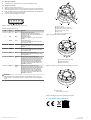
1 Anpresspunkte
2 Halbkreisförmige Aussparungen
3 M4 Gewindebohrungen für Befestigungsschrauben
4 Bohrung für Befestigungsschrauben
5 Motorwelle
6 Schrauben für Abdeckung Kabelabgang
6
1
2
5
34
Abbildung 2: SEy70/90: Gerätebeschreibung
1
2
3
4
5
1 Schrauben für Hohlwellenklemmung
2 Hohlwellenklemmung
3 Drehrichtung
1
2
3
Abbildung 3: SEy70/90: Montagehinweis Hohlwellenklemmung
1 Befestigungsschrauben
(nicht im Lieferumfang enthalten)
1
Abbildung 4: SEy70/90: Montagehinweis Befestigungsschrauben
7 Konformität mit EU-Richtlinien
8021244/132Z/2019-03-13/de, en SES/SEM70
SES/SEM90 | SICK
2

E N G L I S H e n
1 About this document
Please read these operating instructions carefully before using the SES/SEM70,
SES/SEM90 motor feedback systems or mounting them, putting them into opera‐
tion, or servicing them.
1.1 Purpose of this document
These operating instructions are for giving technical personnel of the machine
manufacturer or operator instructions on the assembly, electrical installation,
commissioning, operation and maintenance of SES/SEM70 and SES/SEM90
motor feedback systems.
1.2 Symbols used
WARNING
A warning indicates a specific or potential hazard. This is intended to protect
you against accidents. Read the safety notes carefully and follow them.
1.3 Associated documents
“HIPERFACE
®
” interface manual, part number 8010701, as of 02.2016 (or
newer)
1.4 Maintenance and repairs
The SES/SEM70 and SES/SEM90 motor feedback systems are maintenance-free.
No repair option is provided in the event of a defect. Please contact us if you have
any complaints. The motor feedback system is not intended for repeated mount‐
ing/dismantling.
1.5 Disposal
b
Always dispose of unusable or irreparable devices in accordance with the
applicable waste disposal regulations specific to your country.
NOTE
We will be glad to help you dispose of these devices. Please contact us.
2 Product description
Encoders of type SES/SEM70 and SES/SEM90 are motor feedback systems that
are ideal for the dynamic and precise operation of servo-control circuits due to
their equipment.
The overall system, consisting of encoder, evaluation system, servo inverter, and
motor, forms a control circuit. Actual values for commutation, rotational speed,
direction of rotation, and position are derived from the encoder signals.
The sensor signals are transferred to the evaluation system via a HIPERFACE
®
interface.
WARNING
The SES/SEM70 and SES/SEM90 motor feedback systems are not safety
components.
3 Generally applicable notes
Switch off the voltage of all affected machines/units during the mounting
process.
The more precise the centering for the motor feedback system, the less the angle
and shaft offset during mounting.
EMC considerations make it mandatory to connect the housing or the encoder to
ground.
The integrated shielded cable ensure this with the SES/SEM70 and SES/SEM90
with shielded cable (part number 2089521).
This must be ensured via the total system with the SES/SEM70 and SES/SEM90
with unshielded cable (part number 2031086).
WARNING
To ensure trouble-free operation, ensure that the motor shielding is con‐
nected properly.
If tolerances are narrow between the motor shaft and the motor feedback system,
pushing the rotor may be more difficult.
When dismantling the motor feedback system, the motor feedback system must
be held on the housing and then pulled off of the motor shaft.
3.1 Preparation for mounting
b
Degrease the drive shaft if necessary.
b
Look for any damage!
4 SES/SEM70 motor feedback system
4.1 Tools/parts required
3 M3 cylinder head screws according to ISO 4762 (DIN 912) or similar screws
with a minimum strength of 8.8 are required for mounting the motor feedback
system. Select the screw length (at least 20 mm) and screw head type according
to the mounting conditions.
An SW2 Allen wrench is required for mounting or dismantling the hollow-shaft
clamp.
4.2 Mounting
b
Block the customer's drive shaft.
b
Push the rotor of the SES/SEM70 carefully onto the motor shaft using 4
pressure points to ensure parallel alignment of the rotor and the motor
shaft.
NOTE
Please make sure that the centering collar of the motor feedback sys‐
tem does not snap completely into the centering collar of the motor
flange.
b
A defined gap is created due to the geometry of the centering collar with the
forms on the rear side of the motor feedback system. This makes it possible
to adjust the motor feedback system without a mounting tool.
b
Gently press the rotor down to the stop and tighten the screws of the hollow-
shaft clamp in number order (screws 1-5).
Screw tightening torque (hollow-shaft clamp): 0.4 Nm.
b
In the second work stop, the screws must be tightened in the reverse order
from before.
Screw tightening torque (hollow-shaft clamp): 0.7 Nm.
b
Turn the housing until it engages in the centering collar
b
The housing must be fixed to the flange with 3 screws (not included with
delivery).
Screw tightening torque (housing): 1.0 Nm ± 10% Nm.
4.3 Dismantling
b
Block the customer's drive shaft.
b
Loosen 2 screws of the cable outlet and remove the cover.
b
De-energize and pull out the set of stranded wires and remove the strain
relief.
b
Unscrew the screws on the encoder housing and the hollow-shaft clamp and
remove them.
b
The encoder can be removed. Hold the encoder on the housing and pull off
of the shaft.
5 SES/SEM90 motor feedback system
5.1 Tools/parts required
3 M4 cylinder head screws according to ISO 4762 (DIN 912) or similar screws
with a minimum strength of 8.8 are required for mounting the motor feedback
system. Select the screw length (at least 20 mm) and screw head type according
to the mounting conditions.
An SW2 Allen wrench is required for mounting or dismantling the hollow-shaft
clamp.
5.2 Mounting
b
Block the customer's drive shaft.
b
Push the rotor of the SES/SEM90 carefully onto the motor shaft using 4
pressure points to ensure parallel alignment of the rotor and the motor
shaft.
NOTE
Please make sure that the centering collar of the motor feedback sys‐
tem does not snap completely into the centering collar of the motor
flange.
b
A defined gap is created due to the geometry of the centering collar with the
forms on the rear side of the motor feedback system. This makes it possible
to adjust the motor feedback system without a mounting tool.
b
Gently press the rotor down to the stop and tighten the screws of the hollow-
shaft clamp in number order (screws 1-5).
Screw tightening torque (hollow-shaft clamp): 0.4 Nm.
b
In the second work stop, the screws must be tightened in the reverse order
from before.
Screw tightening torque (hollow-shaft clamp): 0.7 Nm.
b
Turn the housing until it engages in the centering collar
b
The housing must be fixed to the flange with 3 screws (not included with
delivery).
Screw tightening torque (housing): 2.3 Nm ± 10% Nm.
5.3 Dismantling
b
Block the customer's drive shaft.
b
Loosen 3 screws of the cable outlet and remove the cover.
b
De-energize and pull out the set of stranded wires and remove the strain
relief.
b
Unscrew the screws on the encoder housing and the hollow-shaft clamp and
remove them.
b
The encoder can be removed. Hold the encoder on the housing and pull off
of the shaft.
6 Electrical installation
WARNING
Observe the following points in relation to electrical installation of the SES/
SEM70 and SES/SEM90 motor feedback systems.
b
To connect the sensors, refer to the corresponding operating instructions for
the external drive system or for the higher-order control system.
b
Never establish or remove electrical connections to the motor feedback sys‐
tem with the voltage switched on, since that could result in a faulty device.
8021244/132Z/2019-03-13/de, en SES/SEM70
SES/SEM90 | SICK
3

6.1 Tools/parts required
b
A TX8 Torx tool is required for mounting or dismantling the cover.
6.2 Interface connection
b
Remove the cover using a Torx tool.
b
While de-energized, insert the male connector for the set of stranded wires
into the female connector on the encoder far enough that it clicks into place.
b
Insert the cable into the strain relief. With a shielded cable, the shield sleeve
must be inserted into the provided notch.
b
Close the cover and tighten the screws.
Figure 1: Series connector connection type, 8-pin
Interface pin assignment, 8-pin
PIN Signal Wire colors Definition
1 V
S
Red Supply voltage to the encoder
The supply voltage range of the encoder is
between +7 V and +12 V. The recommended sup‐
ply voltage is +11 V.
2 +SIN White Process data channel
+SIN is a sine signal of 1 V
pp
with a static offset of
REFSIN.
3 REFSIN Brown Process data channel
A +2.3 V static voltage which serves as the refer‐
ence voltage for +SIN.
4 +COS Pink Process data channel
+COS is a sine signal of 1 V
pp
with a static offset of
REFCOS.
5 REFCOS Black Process data channel
A +2.3 V static voltage which serves as the refer‐
ence voltage for +COS.
6 GDN Blue Ground connection of the encoder
Electrically isolated from the housing The voltage
relating to GND is + V
S
.
7 Data + Gray or yel‐
low
Parameter channel; positive data signal
The parameter channel is an asynchronous, half-
duplex interface, which physically conforms to the
EIA RS485 specification. For this, data can be
requested from the encoder through different
commands; this also makes it possible to write
user-specific data such as position offset to the
EEPROM of the encoder.
8 Data Green or
violet
Parameter channel; negative data signal
The parameter channel is an asynchronous, half-
duplex interface, which physically conforms to the
EIA RS485 specification. For this, data can be
requested from the encoder through different
commands; this also makes it possible to write
user-specific data such as position offset to the
EEPROM of the encoder.
WARNING
PIN assignment only valid for standard motor feedback systems. For cus‐
tomer-specific motor feedback systems, please use the corresponding data
sheet.
1 Pressure points
2 Halbkreisförmige Aussparungen
3 M4 threaded holes for fixing screws
4 Bore hole for fixing screws
5 Motor shaft
6 Screws for the cable outlet cover
6
1
2
5
34
Figure 2: SEy70/90: device description
1
2
3
4
5
1 Screws for hollow-shaft clamp
2 Hollow-shaft clamp
3 Direction of rotation
1
2
3
Figure 3: SEy70/90: hollow-shaft clamp operating instructions
1 Fixing screws
(Not included with delivery)
1
Figure 4: SEy70/90: fixing screw operating instructions
7 Compliance with EU Directives
8021244/132Z/2019-03-13/de, en SES/SEM70
SES/SEM90 | SICK
4
-
 1
1
-
 2
2
-
 3
3
-
 4
4


SICK SES/SEM70, SES/SEM90 Motor feedback system rotary HIPERFACE® Bedienungsanleitung
- Typ
- Bedienungsanleitung
in anderen Sprachen
Verwandte Artikel
-
SICK SEK90, SEK160, SEK260 Motor feedback system rotary HIPERFACE® Bedienungsanleitung
-
-
-
-
-
-
-
-
-