
GCE CENTRAL GAS SYSTEMS
IMPORTANT!
Read carefully before use! Keep the manual for future consultation!
WICHTIG!
Vor Gebrauch sorgfältig lesen!
Bewahren Sie die Gebrauchsanweisung für späteres Nachschlagen auf!
INSTRUCTION FOR USE
GEBRAUCHSANLEITUNG
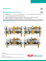
MANIFOLD
ENTSPANNUNGSSTATION
EN
DE
M MANIFOLD | T TEC | M MID FLOW | H0 HIGH PRESSURE WITH FKM |
HE HIGH PRESSURE WITH EPDM ORING |
HS HIGH PRESSURE REGULATOR WITH SST VALVE + EPDM ORINGS |
S SEMIAUTOMATIC CHANGE OVER | S SINGLE STAGE

2/64
EN
CONTENT
1. GENERAL ......................................................................................................................................................................................... 4
1.1. INFORMATION ABOUT THIS INSTRUCTIONS MANUAL ............................................................................................................ 4
1.2. INFORMATION ABOUT THIS MANIFOLD .................................................................................................................................. 4
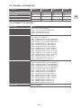
1.2.1. MTMH0SSS, MTMHESSS, MTMHSSSS .............................................................................................................................. 5
1.2.2. MTMH0SSP, MTMHESSP, MTMHSSSP .............................................................................................................................. 5
1.3. EXPLANATION OF SYMBOLS .................................................................................................................................................... 6
1.4. LIMITATIONS OF LIABILITY ........................................................................................................................................................ 6
1.5. COPYRIGHT .................................................................................................................................................................................7
1.6. SPARE PARTS ..............................................................................................................................................................................7
1.7. WARRANTY PROVISION ..............................................................................................................................................................7
1.8. CUSTOMER SERVICE ..................................................................................................................................................................7
2. SAFETY ............................................................................................................................................................................................7
2.1. INTENDED USE ............................................................................................................................................................................7
2.1.1. STRUCTURAL CHANGES AT THE MANIFOLD ................................................................................................................... 8
2.2. FUNDAMENTAL RISKS .............................................................................................................................................................. 8
2.3. OPERATOR’S RESPONSIBILITY ................................................................................................................................................. 9
2.4. PERSONNEL REQUIREMENTS .................................................................................................................................................. 9
2.4.1. QUALIFICATIONS .............................................................................................................................................................. 9
2.4.2. UNAUTHORIZED PERSONNEL .......................................................................................................................................10
2.4.3. TRAINING ........................................................................................................................................................................10
2.5. PERSONAL PROTECTIVE EQUIPMENT ....................................................................................................................................10
2.6. BEHAVIOR IN CASE OF FIRE OR ACCIDENT ............................................................................................................................11
2.7. ENVIRONMENTAL PROTECTION ...............................................................................................................................................11
2.8. SIGNAGE ...................................................................................................................................................................................12
2.8.1. SIGNS THAT GIVE ORDERS .............................................................................................................................................12
2.8.2. SIGNS INDICATING BANS ............................................................................................................................................... 12
2.8.3. WARNING SIGNS ............................................................................................................................................................. 12
3. TECHNICAL SPECIFICATIONS ................................................................................................................................................. 13
3.1. FLOW SCHEME MTMH0SSP, MTMHESSP, MTMHSSSP ........................................................................................................13
3.2. DIMENSION SHEET MTMH0SSP, MTMHESSP, MTMHSSSP ................................................................................................14
3.3. FLOW SCHEME MTMH0SSS, MTMHESSS, MTMHSSSS.......................................................................................................15
3.4. DIMENSION SHEET MTMH0SSS, MTMHESSS, MTMHSSSS ................................................................................................16
3.5. GENERAL INFORMATION ......................................................................................................................................................... 17
3.6. CONNECTION VALUES ............................................................................................................................................................17
3.7. PERFORMANCE VALUE.............................................................................................................................................................18
3.8. OPERATING CONDITIONS .......................................................................................................................................................18
4. SETUP AND FUNCTION .......................................................................................................................................................... 18
4.1. OVERVIEW MTMH0SSS0, MTMHESSS0, MTMHSSSS0 SPECIAL U ..................................................................................18
4.2. OVERVIEW MTMH0SSSS, MTMHESSSS, MTMHSSSSS SPECIAL U .................................................................................19
4.3. OVERVIEW MTMH0SSP0, MTMHESSP0, MTMHSSSP0 SPECIAL U .................................................................................19
4.4. OVERVIEW MTMH0SSPS, MTMHESSPS, MTMHSSSPS SPECIAL U ................................................................................20
4.5. BRIEF DESCRIPTION MTMH0SS, MTMHESS, MTMHSSS .......................................................................................................20
5. TRANSPORT, PACKAGING AND STORAGE .........................................................................................................................21
5.1. SAFETY INFORMATION FOR TRANSPORTATION ....................................................................................................................21
5.2. TRANSPORT INSPECTION .......................................................................................................................................................21
5.3. PACKAGING ..............................................................................................................................................................................21
5.4. STORAGE ................................................................................................................................................................................. 22

3/64
EN
6. INSTALLATION AND INITIAL STARTUP .............................................................................................................................. 22
6.1. SAFETY NOTES FOR INSTALLATION AND INITIAL STARTUP ................................................................................................ 22
6.2. PREPARATION .........................................................................................................................................................................22
6.3. INSTALLATION ......................................................................................................................................................................... 22
6.4. REQUIRED QUALIFICATIONS FOR INITIAL STARTUP AND CYLINDER ..................................................................................................
CHANGING ....................................................................................................................................................................................23
6.5. INITIAL START UP .................................................................................................................................................................... 23
6.5.1. PROCESS GAS PURGING MTMH0SSP, MTMHESSP, MTMHSSSP ..................................................................................24
6.5.2. FILL THE PROCESS GAS TUBING WITH PROCESS GAS ...............................................................................................25
6.5.3. CHANGE EMPTY GAS CYLINDER ..................................................................................................................................25
6.5.4. TAKING MANIFOLD OUT OF OPERATION ....................................................................................................................25
6.6. TESTS ......................................................................................................................................................................................25
7. OPERATION .................................................................................................................................................................................25
8. MAINTENANCE ..........................................................................................................................................................................26
8.1. SAFETY NOTES FOR MAINTENANCE ......................................................................................................................................26
8.2. MAINTENANCE PLAN .............................................................................................................................................................26
8.3. MAINTENANCE WORK ............................................................................................................................................................26
8.3.1. CLEANING .......................................................................................................................................................................26
8.3.2. REQUIREMENTS FOR MAINTENANCE ..........................................................................................................................26
8.3.3. NECESSARY MAINTENANCE .........................................................................................................................................26
8.4. MEASURES FOLLOWING MAINTENANCE .............................................................................................................................. 27
9. TROUBLESHOOTING ............................................................................................................................................................... 27
9.1. SAFETY NOTES FOR TROUBLESHOOTING ............................................................................................................................27
10. DISMANTLING AND DISPOSAL ...........................................................................................................................................29
10.1. SAFETY NOTES FOR DISMANTLING AND DISPOSAL ...........................................................................................................29
10.2. DISMANTLING ........................................................................................................................................................................29
10.3. DISPOSAL ............................................................................................................................................................................... 30

4/64
EN
1. GENERAL
1.1. INFORMATION ABOUT THIS INSTRUCTIONS MANUAL
This instruction is only intended for use with the manifold product type:
• MTMH0SSS, MTMHESSS, MTMHSSSS
• MTMH0SSP, MTMHESSP, MTMHSSSP
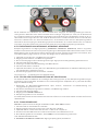
Manifolds of this type are suitable to take gas out of gas cylinder or bundle and reduce the pressure. These
manifolds were installed as permanently wall assembly and are connected to gas cylinder or bundle with
coil or hose.
These instructions enable you to operate the system safely and e ciently. These instructions form an integral
part of the system and must always be kept with the system and within easy reach of sta .
Prior to commencing any work, the sta must read these instructions carefully and understand the contents.
Observance of all the safety information and instructions for operation that are contained in these instructions
is essential to ensure work safety.
Local accident prevention regulations and general safety regulations governing the use of the system must
also be observed.
Illustrations in these instructions serve to ensure a basic understanding of the system and may di er from
the actual version.
1.2. INFORMATION ABOUT THIS MANIFOLD
Manifolds of this type are only suitable for gases defi ned as standard gas. The maximum working pressure
for these manifolds is 300 bar.
Single stage manifolds consist of valves and a pressure regulator with metal diaphragm, created and ap-
proved as ISO7291/ISO10297 including oxygen shock test.
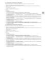
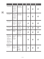
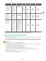
Product line DruvaTEC Line MID Flow
(Brass)
H0 - High Pressure Regulator
with FKM Relief Valve Seat
• Suitable Gases (including their mixtures)
• Industrial
• Inert
• Flammable
• Oxidizing
• O
• Not Suitable Gases (including their mixtures)
• Corrosive
• Toxic
• CO, NO
HE - High Pressure Regulator
with EPDM Relief Valve Seat
• Suitable Gases (including their mixtures)
• Industrial
• Inert
• Flammable
• Oxidizing
• CO, NO
• Not Suitable Gases (including their mixtures)
• Corrosive
• Toxic
• O
HS – High Pressure Regulator
with stainless steel internal parts
& EPDM O-Rings
Gas mixture with low content of nitric oxide (NO)
ENGLISH
INSTRUCTION FOR USE: MANIFOLD

5/64
EN
1.2.1. MTMH0SSS, MTMHESSS, MTMHSSSS
This manifold is available in brass. It consists of the following components:
• Pressure Regulator with inlet and outlet pressure gauge
• Option -S: 4-Port Shut-o valve at inlet
• Relief Valve
• Front and ground plate
• Option -S: 4-Port Shut-o valve at outlet
SPECIALS
• 0 - WITHOUT
• C - CHECK VLV
• F - SAFETY DEV. FLAM.
• G - CHECK VLV + SAFETY DEV. FLAM.
• H - CHECK VLV + SAFETY VLV + SAFETY DEV. FLAM.
• N - SAFETY DEV. OXY/AIR
• P - CHECK VLV + SAFETY DEV. OXY/AIR
• Q - CHECK VLV + SAFETY VALVE + SAFETY DEV. OXY/AIR
• S - SAFETY VLV
• U - CHECK VLV + SAFETY VLV
• Y - SAFETY DEV. FLAM. + SAFETY VLV
• Z - SAFETY DEV. OXY/AIR + SAFETY VLV
1.2.2. MTMH0SSP, MTMHESSP, MTMHSSSP
This manifold is available in brass. It consists of the following components:
• Pressure Regulator with inlet and outlet pressure gauge
• Option -P: Purge valve for process gas purging and 4-Port Shut-o valve at inlet
• Relief Valve
• Front and ground plate
• Option -S: 4-Port Shut-o valve at outlet
SPECIALS
• 0 - WITHOUT
• C - CHECK VLV
• F - SAFETY DEV. FLAM.
• G - CHECK VLV + SAFETY DEV. FLAM.
• H - CHECK VLV + SAFETY VLV + SAFETY DEV. FLAM.
• N - SAFETY DEV. OXY/AIR
• P - CHECK VLV + SAFETY DEV. OXY/AIR
• Q - CHECK VLV + SAFETY VALVE + SAFETY DEV. OXY/AIR
• S - SAFETY VLV
• U - CHECK VLV + SAFETY VLV
• Y - SAFETY DEV. FLAM. + SAFETY VLV
• Z - SAFETY DEV. OXY/AIR + SAFETY VLV

6/64
EN
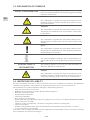
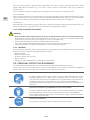
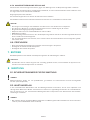
1.3. EXPLANATION OF SYMBOLS
SAFETY INFORMATION Safety information is highlighted by symbols in these instruc-
tions. This safety information is preceded by signal words that
defi ne the extent of risk.
DANGER!
This combination of symbol and signal word indicates an im-
mediately dangerous situation that will cause death or severe
injury if not avoided.
WARNING!
This combination of symbol and signal word indicates a pos-
sibly dangerous situation that can cause death or severe injury
if not avoided.
BEWARE!
This combination of symbol and signal word indicates a pos-
sibly dangerous situation that can cause minor injury if not
avoided.
NOTE!
This combination of symbol and signal word indicates a pos-
sibly dangerous situation that can cause property and environ-
mental damage if not avoided.
TIPS AND RECOMMENDATIONS
This symbol highlights useful tips and recommendations, to-
gether with help for ensuring e cient and trouble-free opera-
tion.
SPECIAL SAFETY
INFORMATION
The following symbols are used in the safety information to
draw your attention to particular risks.
DANGER!
This combination of symbol and signal word indicates an im-
mediately dangerous situation involving electrical current. Ig-
noring such a warning could result in severe or fatal injuries.
1.4. LIMITATIONS OF LIABILITY
All of the information and notes in these instructions have been compiled in accordance with applicable
standards and regulations. They refl ect best engineering practice and our years of experience.
The manufacturer accepts no liability for damages in the following instances:
• Failure to observe these instructions
• Utilization of the system for any other than the intended purpose
• Operation by untrained sta
• Unauthorized modifi cations
• Technical modifi cations
• Use of unlicensed spare parts
• Working with the gas supply panel when any safety device is broken or not functional mounted or safety
devices don’t work correctly
• Improper control of components, connections and gaskets, which are wearing parts.
• Incorrect reparations
• Violation of temperature limits, which are dedicated in the datasheet during operation or storage
• In case of disaster or force majeure
The actual scope of supply may di er from the explanations and illustrations in these instructions following
the incorporation of new technical changes.

7/64
EN
The obligations stipulated in the supply agreement, our general terms and conditions of business, the manu-
facturer’s terms and conditions of supply and the statutory regulations in force at the time of contract conclu-
sion apply.
1.5. COPYRIGHT
The contents of these instructions are protected by copyright. They may be used in connection with the
operation of the system. Any other use above and beyond the aforementioned is only permitted with the
written consent of the manufacturer.
1.6. SPARE PARTS
WARNING!
• Risk of injury from using incorrect spare parts!
• The use of incorrect or defective spare parts can result in risks for the operating sta and in damages,
malfunctions or total failure of the system.
• Only use original spare parts from the manufacturer or spare parts authorized by the manufacturer.
• Always consult the manufacturer if in doubt.
LOSS OF WARRANTY
• The manufacturer’s warranty lapses if unauthorized spare parts are used.
1.7. WARRANTY PROVISION
The warranty provisions are included in the manufacturer’s general terms and conditions of business. See
chapter VI. Warranty Claims.
1.8. CUSTOMER SERVICE
GCE GmbH
Weyherser Weg 8
DE-36043 Fulda
www.gcegroup.com
Please do not hesitate to provide us with information and experiences gained through use; we welcome any
valuable input that will help to improve our products.
2. SAFETY
This section provides an overview of all the important safety aspects to ensure the protection of your sta
and the safe and trouble-free operation of the equipment. Further safety information relating to specifi c tasks
can be found in the sections on the individual life cycle phases.
2.1. INTENDED USE
The manifold is only usable for the defi ned standard gases and pressures observing the given temperature
range. The maximum fl ow is 100 m/h.
Intended use also includes compliance with all the information in these instructions and compliance with
reparation, maintenance working, type label and data sheets.
Any use other than, or above and beyond, the intended use constitutes improper use.
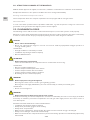
WARNING!
• Danger from improper use!
• Improper use of the system can lead to dangerous situations.
• Never use the manifold with liquid fl uids.

8/64
EN
2.1.1. STRUCTURAL CHANGES AT THE MANIFOLD
Without written approval of supplier, no extensions, additions or alternations are allowed on the manifold.
Components which are not in perfect condition have to be changed immediately.
Cleaning of manifold and disposal of residues
Used components which are ready for reparation has to be purged with an inert gas before.
Noise Generation
In some cases when specifi c infl uence quantities collaborate, e.g. fl ow and pressure range can cause noise
generation or the gas itself. If this happens please contact supplier.
2.2. FUNDAMENTAL RISKS
The following section addresses the residual risks that may arise, even if the system is used properly.
Observance of the safety information included below and in other sections of these instructions is mandatory
in order to reduce the risk of injury and property damage and to avoid dangerous situations.
DANGER!
• Gases can be life threatening!
• Gases can supersede the oxygen in air. This can result in death by asphyxiation. Oxygen produces a
strongly oxidizing e ect.
THEREFORE:
• Enough ventilation is absolutely essential.
• Installation only through certifi ed company.
• Observe ATEX directive
ATTENTION!
• Risk of injury from environment!
There can be malfunctions on component due to condensation and/ or icing.
THEREFORE:
• Observe suitable temperatures.
• Protect component from liquids from outside
• Protect component from dust from outside
• Protect component from weather conditions
• Grounding has to be mounted properly
WARNING!
• Risk of injury from using oil and grease!
Oil and grease must never be used in gas regulating systems.
Oil and grease are highly infl ammatory and can react violently to certain pressurized gases.
THEREFORE:
• Never use oil and grease
WARNING!
• Risk of injury from residual energy stored in the system!
If handled incorrectly, pressurized components can move uncontrollably and cause severe injury. If handled
incorrectly or defective, pressurized components can leak gas under high pressure and cause severe or
even fatal injuries.
BEFORE STARTING WORK WITH THESE COMPONENTS:
• Installation only through certifi ed company.
• Always wear protective goggles when working.
• Always wear ear protection.
• Make sure the equipment is depressurized. Also make sure the residual energy is discharged.
• Always ensure that gas cannot leak unintentionally.
• Make sure that defective components that are pressurized during operation are immediately replaced by
trained sta .

9/64
EN
WARNING!
• Danger of accident!
Due to wrong installation there can be serious or even mortal injuries.
THEREFORE:
• During installation the component should be kept safe
• Never throw the component
Pressurised components are only for intended use.
If there are mechanical damages at tubing or components the whole system must be put in a safe condition.
A ected area must be blocked. Troubles which could infl uence safety, must be eliminated through qualifi ed
sta or supplier.
Especially with gases failure in pressure regulator could happen. Indications for defective regulator is no fl ow
or immediately rising outlet pressure. In this case system must be shut-o and the relevant department for
maintenance must be informed. Never close exhaust piping.
2.3. OPERATOR’S RESPONSIBILITY
OPERATOR
The operator is the person who operates the system for commercial or business purposes or who provides
the system for use/application by a third party, and who bears legal product responsibility for protecting the
user, sta or third parties during operation.
OPERATOR’S DUTIES
The system is used for commercial purposes. The operator of the system is therefore subject to legal work
safety obligations.
Compliance with the safety, accident prevention and environmental protection regulations that apply for the
use of the system is mandatory, in addition to the safety information in these instructions.
THE FOLLOWING APPLIES IN PARTICULAR:
• The operator must be aware of the applicable work safety regulations and must perform a risk assessment
to identify risks that may occur as a result of the specifi c working conditions at the site where the system
is operated. The operator must use this assessment as the basis for compiling instructions for operating
the system.
• During the entire period in which the system is operated, the operator must ensure that these operating
instructions comply with the latest regulations, and must update the instructions if necessary.
• The operator must assign clear and specifi c responsibility for installation, operation, troubleshooting,
maintenance and cleaning.
• The operator must ensure that all members of sta who work with the system have read and understood
these instructions. The operator must also ensure that these members of sta are trained at regular inter-
vals and are aware of the risks.
• The operator must provide the sta with the requisite protective equipment and bindingly obligate the
sta to wear the necessary protective equipment.
In addition, the operator is responsible for ensuring full technical reliability of the system at all times.
AS SUCH, THE FOLLOWING APPLIES:
• The operator must ensure compliance with the maintenance intervals specifi ed in these instructions.
• The operator must ensure that all safety equipment is regularly inspected for functional reliability and
completeness.
2.4. PERSONNEL REQUIREMENTS
2.4.1. QUALIFICATIONS
The various tasks described in these instructions constitute di ering requirements in respect of the qualifi ca-
tions of the sta charged with performing these tasks.
WARNING!
• Danger if sta is insu ciently qualifi ed!
• Insu ciently qualifi ed sta is not able to assess the risks associated with the system and expose both
themselves and others to the risk of severe or fatal injury.
• Ensure that all works are only performed by sta qualifi ed for the specifi c task.
• Keep insu ciently qualifi ed people out of the work area.

10/64
EN
The works must always be assigned only to individuals who can be trusted to perform the works reliably.
People with impaired reactions, e.g. as a result of drugs, alcohol or medication, must not be allowed to
perform works.
These instructions defi ne the qualifi cations below that are necessary for the respective tasks:
GAS ENGINEER:
Have a professional training, skills and experience and the knowledge of the pertinent standards and regula-
tions to perform works on gas systems and to identify potential hazards. Gas engineers are trained specifi -
cally for the site where they work and are familiar with all relevant standards and regulations.
TECHNICIAN
Have the professional training, skills and experience and the knowledge of the pertinent standards and regu-
lations to perform the assigned works and to identify and avoid potential hazards.
2.4.2. UNAUTHORIZED PERSONNEL
WARNING!
• Risks associated with unauthorized personnel in the hazard and work areas can be life threatening!
• Unauthorized individuals without the qualifi cations described in this section are not familiar with the risks
in the work area. As such, they are in danger of severe or even fatal injury.
• Keep unauthorized personnel away from the hazard and work area.
• If in doubt, approach individuals and instruct them to leave the hazard and work area.
• Stop any work while unauthorized individuals are in the hazard and work area.
2.4.3. TRAINING
The operator must train the sta at regular intervals. A training log must be maintained for purposes of better
tracking and must contain the following information, at least:
• Date of training
• Names of trained sta
• Contents of the training session
• Name of trainer
• Signatures of the sta members in training and of the trainer
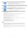
2.5. PERSONAL PROTECTIVE EQUIPMENT
Personal protective equipment protects sta from safety and health hazards while working.
Various tasks on and associated with, the system necessitate the use of personal protective equipment,
which is described in more detail in the individual sections of these instructions.
BREATHING APPARATUS
To protect against harmful gases, vapors, dust and similar materials and media.
Breathing apparatus (e.g. compressed air respirator) must be used when an oxy-
gen content of at least 17% in the ambient air is not guaranteed or when the limit of
a hazardous substance in the ambient air is exceeded more than 100-fold.
Breathing apparatus may only be worn by people who have been specially trained
in the use.
BREATHING APPARATUS, DEPENDENT ON AIR CIRCULATION
To protect against harmful gases, vapors, dust and similar materials and media.
Breathing apparatus must be worn if a permissible limit is exceeded 100-fold.
The breathing apparatus may only be used when the oxygen content in the ambi-
ent air measures at least 17%.
PROTECTIVE GOGGLES
To protect the eyes against airborne parts and splashes of liquid.

11/64
EN
CHEMICAL-RESISTANT GLOVES
To protect the hands from aggressive substances.
Make sure the protective gloves are leak-proof before wear,
Before taking the gloves o , clean them and then store them in a well ventilated
location.
PROTECTIVE GLOVES
To protect the hands against abrasion, scrapes, pricks or deeper injuries
and contact with hot or cold surfaces.
EAR PROTECTION
To protect the ears from noise and prevent acoustic trauma.
2.6. BEHAVIOR IN CASE OF FIRE OR ACCIDENT
PREVENTIVE MEASURE
• Always be prepared for fi res and accidents!
• Always keep fi rst aid equipment (kit, blankets, etc.) and fi re extinguishing equipment in working order and
close to hand.
• Familiarize the sta with accident reporting, fi rst aid and emergency procedures.
• Keep the access routes free for emergency service vehicles.
MEASURES IN THE EVENT OF FIRE OR ACCIDENT
• If there is no risk to your own safety, remove people from the danger zone.
• Administer fi rst aid if necessary.
• Notify the fi re brigade and/or emergency service.
• In the event of fi re: If there is no risk to your own safety, use fi re extinguishing equipment to fi ght the fi re
until the fi re brigade arrives.
• Inform the person responsible at the location.
• Make sure the access routes are free for emergency service vehicles.
• Direct the emergency service vehicles.
2.7. ENVIRONMENTAL PROTECTION
NOTE!
• Risk of environmental pollution from incorrect handling of environmentally hazardous substances!
• The environment can su er substantial damage if environmentally hazardous substances are handled,
and especially disposed of, incorrectly.
• Always observe the information below on handling environmentally hazardous substances and their dis-
posal.
• Take immediate measures if environmentally hazardous substances are accidentally released into the
environment. If in doubt, notify the responsible local authorities about the damage and enquire about the
suitable measures to be taken.

12/64
EN
2.8. SIGNAGE
WARNING!
• Danger from illegible signs!
• Labels and signs can gather dirt or become otherwise illegible over time, thus preventing the recognition
of risks and compliance with the requisite operating information. This could result in injury.
• Make sure all safety, warning and operation information is legible at all times.
• Immediately replace any damaged signs or labels.
2.8.1. SIGNS THAT GIVE ORDERS
• No signs
2.8.2. SIGNS INDICATING BANS
• No signs
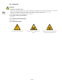
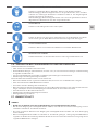
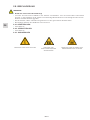
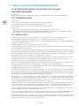
2.8.3. WARNING SIGNS
GAS BOTTLES HAZARD EXPLOSION HAZARDOUS
AREA
WARNING OF TOXIC AND/ OR
CORROSIVE SUBTANCES

13/64
EN
3. TECHNICAL SPECIFICATIONS
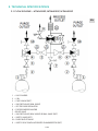
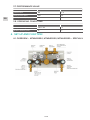
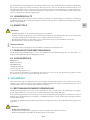
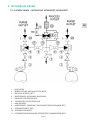
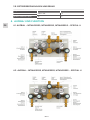
3.1. FLOW SCHEME MTMH0SSP, MTMHESSP, MTMHSSSP
1 – GAS CYLINDER
2 – COIL
3 – CHECK VALVE (OPT.)
4 – SHUT-OFF VALVE (3XIN; 1XOUT)
5 – SET PRESSURE REGULATOR
6 – FIX PRESSURE REGULATOR
7 – RELIEF VALVE
8 – SHUT-OFF VALVE (1XIN; 3XOUT) OR BALL VALVE (OPT.)
9 – SAFETY VALVE (OPT.)
10 – PURGE OUTLET VALVE
11 – SAFETY DEVICE WITH INTEGRATED FLAMEARRESTOR (OPT.)

14/64
EN
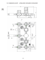
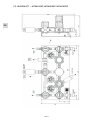
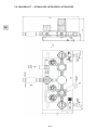
3.2. DIMENSION SHEET MTMH0SSP, MTMHESSP, MTMHSSSP

15/64
EN
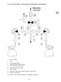
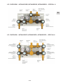
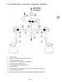
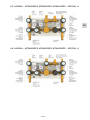
3.3. FLOW SCHEME MTMH0SSS, MTMHESSS, MTMHSSSS
1 – GAS CYLINDER
2 – COIL
3 – CHECK VALVE (OPT.)
4 – SHUT-OFF VALVE (3XIN, 1XOUT)
5 – SET PRESSURE REGULATOR
6 – FIX PRESSURE REGULATOR
7 – RELIEF VALVE
8 – SHUT-OFF VALVE (1XIN; 3XOUT) OR BALL VALVE (OPT.)
9 – SAFETY VALVE (OPT.)
10 – SAFETY DEVICE WITH INTEGRATED FLAMEARRESTOR (OPT.)
3.2. DIMENSION SHEET MTMH0SSP, MTMHESSP, MTMHSSSP

16/64
EN
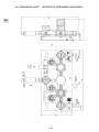
3.4. DIMENSION SHEET MTMH0SSS, MTMHESSS, MTMHSSSS

17/64
EN
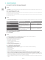
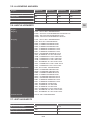
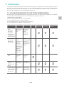
3.5. GENERAL INFORMATION
Information MTMH0SSS MTMHESSS MTMH0SSP MTMHESSP
Max. weight [kg] 9,6 9,6 10,5 10,5
Length [mm] 400 400 400 400
Depth [mm] 150 150 150 150
Max. height [mm] 364 364 364 364
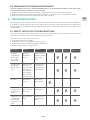
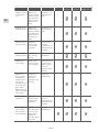
3.6. CONNECTION VALUES
Information Value
Inlet N38F - NPT3/8 INCH FEMALE
E2MR - G3/8 INCH MALE EN560 RIGHT
W2ML - W21.8X1/4 MALE LEFT
W2MR - W21.8X1/4 MALE RIGHT
Outlet N38F - NPT3/8 INCH FEMALE
G12F - G1/2 INCH FEMALE
M12B - COMPRESSION FITTING 12MM BRASS
M15B - COMPRESSION FITTING 15MM BRASS
M18B - COMPRESSION FITTING 18MM BRASS
M12S - COMPRESSION FITTING 12MM SS
M15S - COMPRESSION FITTING 15MM SS
M18S - COMPRESSION FITTING 18MM SS
M25S - COMPRESSION FITTING 25MM SS
IX8B - COMPRESSION FITTING 1/2" BRASS
IX10B - COMPRESSION FITTING 5/8" BRASS
IX12B - COMPRESSION FITTING 3/4" BRASS
IX14B - COMPRESSION FITTING 7/8" BRASS
IX8S - COMPRESSION FITTING 1/2" SS
IX12S - COMPRESSION FITTING 3/4" SS
IX16S - COMPRESSION FITTING 1" SS
Outlet Purge Valve (if existent) N14F - NPT1/4 INCH FEMALE
M06B - COMPRESSION FITTING 6MM BRASS
M08B - COMPRESSION FITTING 8MM BRASS
M10B - COMPRESSION FITTING 10MM BRASS
M12B - COMPRESSION FITTING 12MM BRASS
M06S - COMPRESSION FITTING 6MM SS
M08S - COMPRESSION FITTING 8MM SS
M10S - COMPRESSION FITTING 10MM SS
M12S - COMPRESSION FITTING 12MM SS
IX4B - COMPRESSION FITTING 1/4" BRASS
IX6B - COMPRESSION FITTING 3/8" BRASS
IX8B - COMPRESSION FITTING 1/2" BRASS
IX4S - COMPRESSION FITTING 1/4" SS
IX6S - COMPRESSION FITTING 3/8" SS
IX8S - COMPRESSION FITTING 1/2" SS
Safety valve NPT1/2" FEMALE

18/64
EN
3.7. PERFORMANCE VALUE
Information Value Unit
Nominal fl ow 100 m3/h
Inlet pressure (max.) 300 bar
Outlet pressure (max.) 100 bar
3.8. OPERATING CONDITIONS
Information Value Unit
Temperature range -20 till +60 °C
Relative humidity (max.) 98 %
4. SETUP AND FUNCTION
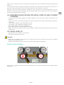
4.1. OVERVIEW MTMH0SSS0, MTMHESSS0, MTMHSSSS0 SPECIAL U

19/64
EN
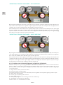
4.2. OVERVIEW MTMH0SSSS, MTMHESSSS, MTMHSSSSS SPECIAL U
4.3. OVERVIEW MTMH0SSP0, MTMHESSP0, MTMHSSSP0 SPECIAL U

20/64
EN
4.4. OVERVIEW MTMH0SSPS, MTMHESSPS, MTMHSSSPS SPECIAL U
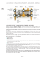
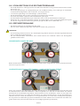
4.5. BRIEF DESCRIPTION MTMH0SS, MTMHESS, MTMHSSS
With the manifold type MTMH0SS, MTMHESS… (material: brass) an industrial, fl ammable, oxidizing, inert,
non-toxic and non-corrosive gas or gas mixture, which can be reduced from maximum 300 bar pressure to
tubing pressure (10 bar, 20 bar, 40 bar, 100 bar).
With the manifold type MTMHSSS… (material: brass) a gas mixture with Gas mixture with low content of nitric
oxide (NO), which can be reduced from maximum 300 bar pressure to tubing pressure (10 bar, 20 bar, 40
bar, 100 bar).
This manifold is able to switch automatically between two high pressure connection sides using a back
pressure di erence of two pressure regulators. The operator of the plant can defi ne the direction of the
switchover at any time.
A relief valve at pressure regulator secures the manifold with its outlet pressure against incorrect pressure
rising at the outlet due to leakage in regulator seat.
Can be added individually or as a combination:
• Inlet Purge Valve
• Outlet Purge Valve
• Outlet Ball Valve
• Inlet Check Valve
• Safety devices according to ISO 5175 with a gas non-return valve, a fl ame arrester and a temperature-
controlled afterfl ow-arrestor at the outlet
• Outlet Safety Valve
• Safety devices according to ISO 5175 with a gas non-return valve, a fl ame arrester and a temperature-
controlled afterfl ow-arrestor at the outlet for oxygen and compressed air
The real inlet and outlet pressure of the manifold is displayed at the pressure gauges. There is the possibility
to use contact gauges for inlet and outlet pressure.
If the manifold has the opportunity for process gas purging, this can be done before initial start-up to remove
contaminates. Furthermore, it is possible to depressurize the high-pressure side before cylinder is changed.
The described system is mounted on a stainless-steel plate. The two plates design enables to mount the
component easy and with less weight.
The cut-outs in the front plate enable to change the gauge without disassembly of the complete manifold. At
the back plate at both sides are holes to connect the cylinder hoses with carabiner hook. To connect ground-
ing, you can fi nd screw at the ground plate.
Seite wird geladen ...
Seite wird geladen ...
Seite wird geladen ...
Seite wird geladen ...
Seite wird geladen ...
Seite wird geladen ...
Seite wird geladen ...
Seite wird geladen ...
Seite wird geladen ...
Seite wird geladen ...
Seite wird geladen ...
Seite wird geladen ...
Seite wird geladen ...
Seite wird geladen ...
Seite wird geladen ...
Seite wird geladen ...
Seite wird geladen ...
Seite wird geladen ...
Seite wird geladen ...
Seite wird geladen ...
Seite wird geladen ...
Seite wird geladen ...
Seite wird geladen ...
Seite wird geladen ...
Seite wird geladen ...
Seite wird geladen ...
Seite wird geladen ...
Seite wird geladen ...
Seite wird geladen ...
Seite wird geladen ...
Seite wird geladen ...
Seite wird geladen ...
Seite wird geladen ...
Seite wird geladen ...
Seite wird geladen ...
Seite wird geladen ...
Seite wird geladen ...
Seite wird geladen ...
Seite wird geladen ...
Seite wird geladen ...
Seite wird geladen ...
Seite wird geladen ...
Seite wird geladen ...
Seite wird geladen ...
-
 1
1
-
 2
2
-
 3
3
-
 4
4
-
 5
5
-
 6
6
-
 7
7
-
 8
8
-
 9
9
-
 10
10
-
 11
11
-
 12
12
-
 13
13
-
 14
14
-
 15
15
-
 16
16
-
 17
17
-
 18
18
-
 19
19
-
 20
20
-
 21
21
-
 22
22
-
 23
23
-
 24
24
-
 25
25
-
 26
26
-
 27
27
-
 28
28
-
 29
29
-
 30
30
-
 31
31
-
 32
32
-
 33
33
-
 34
34
-
 35
35
-
 36
36
-
 37
37
-
 38
38
-
 39
39
-
 40
40
-
 41
41
-
 42
42
-
 43
43
-
 44
44
-
 45
45
-
 46
46
-
 47
47
-
 48
48
-
 49
49
-
 50
50
-
 51
51
-
 52
52
-
 53
53
-
 54
54
-
 55
55
-
 56
56
-
 57
57
-
 58
58
-
 59
59
-
 60
60
-
 61
61
-
 62
62
-
 63
63
-
 64
64


in anderen Sprachen
- English: GCE Manifold Operating instructions
Verwandte Artikel
-
GCE Manifold Bedienungsanleitung
-
-
GCE 2-/ 4-PORT SHUT OFF VALVE Bedienungsanleitung
-
-
-
-
-
-
-
Andere Dokumente
-
Varian 948 Operation And Service Manual
-
 Hach Lange APA 6000 Maintenance And Troubleshooting Manual
-
Buhler GAS 222.21 AMEX Installation And Operation Instructions Manual
-
Buhler GAS 222.31 Ex2 Installation And Operation Instructions Manual
-
Mark G+ Series Technical Manual
-
Ega Master 56885 Bedienungsanleitung
-
Trox X-CUBE Ex Bedienungsanleitung
-
Wacker Neuson BS50-4s Benutzerhandbuch
-
-
