
Gas Analysis
Installation and Operation Instructions
Original instructions
Sample gas probe
ECO
BE460013
01/2020
Bühler Technologies GmbH, Harkortstr. 29, D-40880 Ratingen
Tel. +49 (0) 21 02 / 49 89-0, Fax: +49 (0) 21 02 / 49 89-20
E-Mail: [email protected]
Internet: www.buehler-technologies.com

Bühler Technologies GmbH, Harkortstr. 29, D-40880 Ratingen
Tel. +49 (0) 21 02 / 49 89-0, Fax: +49 (0) 21 02 / 49 89-20
Internet: www.buehler-technologies.com
E-Mail: [email protected]
Read this instruction carefully prior to installation and/or use. Pay at-
tention particularly to all advises and safety instructions to prevent in-
juries. Bühler Technologies can not be held responsible for misusing
the product or unreliable function due to unauthorised modifications.
All rights reserved. Bühler Technologies GmbH 2020
Document information
Document No.......................................................... BE460013
Version.........................................................................01/2020

ECO
Table of Contents
1 Introduction..................................................................................................................................................................................................................... 2
1.1 Intended Use.........................................................................................................................................................................................................2
1.2 Scope of Delivery.................................................................................................................................................................................................. 2
1.3 Ordering Instructions.........................................................................................................................................................................................2
2 Safety instructions......................................................................................................................................................................................................... 3
2.1 Important advice................................................................................................................................................................................................. 3
2.2 General hazard warnings .................................................................................................................................................................................4
3 Transport and storage .................................................................................................................................................................................................. 5
4 Installation and connection ........................................................................................................................................................................................6
4.1 Installation site requirements.........................................................................................................................................................................6
4.2 Installation ............................................................................................................................................................................................................6
4.3 Insulation...............................................................................................................................................................................................................6
4.4 Connecting the Gas Line....................................................................................................................................................................................6
4.5 Electrical connections ........................................................................................................................................................................................ 7
4.5.1 Plug Connection....................................................................................................................................................................................7
5 Operation and controls ................................................................................................................................................................................................8
5.1 Before Start-Up ....................................................................................................................................................................................................8
6 Maintenance....................................................................................................................................................................................................................9
6.1 Backwashing the Inlet Filter.............................................................................................................................................................................9
7 Service and repair......................................................................................................................................................................................................... 10
7.1 Troubleshooting ................................................................................................................................................................................................10
7.2 Spare Parts and Accessories ........................................................................................................................................................................... 10
8 Disposal............................................................................................................................................................................................................................ 11
9 Appendices......................................................................................................................................................................................................................12
9.1 Technical Data.................................................................................................................................................................................................... 12
9.2 Functional diagram .......................................................................................................................................................................................... 12
9.3 Dimensions ..........................................................................................................................................................................................................13
10 Attached Documents................................................................................................................................................................................................... 14
iBühler Technologies GmbHBE460013 ◦ 01/2020

ECO
1 Introduction
1.1 Intended Use
The sample gas probe is intended for installation into gas analysis systems in commercial applications.
Sample gas probes are among the main components in a gas conditioning system.
– Therefore also note the related drawing in the data sheet in the appendix.
– Before installing the device, verify the listed technical data meet the application parameters.
– Further verify all contents are complete.
Please refer to the type plate to identify your model. In addition to the job number/ID number, this also contains the article
number and model designation.
Please note the specific values of the device when connecting, and the correct versions when ordering spare parts.
1.2 Scope of Delivery
– 1 x Sample gas probe
– 1 x Flange gasket and screws
– Product documentation
– Connection and mounting accessories (only optional)
1.3 Ordering Instructions
Item no. Description Material
46 22 290 Sample Gas Probe ECO
46 22 2007 Sampling tube 10, max. 135°C Polyester / 1.4571
46 22 2015 Sampling tube 11, max. 260°C PTFE / 1.4571
46 22 2303 Sampling tube 03, max. 600°C 1.4571
46 22 20071 Spare filter hose Polyester
46 22 20072 Spare filter hose PTFE
2 Bühler Technologies GmbH BE460013 ◦ 01/2020

ECO
2 Safety instructions
2.1 Important advice
Operation of the device is only valid if:
– the product is used under the conditions described in the installation- and operation instruction, the intended application
according to the type plate and the intended use. In case of unauthorized modifications done by the user Bühler Technolo-
gies GmbH can not be held responsible for any damage,
– when complying with the specifications and markings on the nameplates.
– the performance limits given in the datasheets and in the installation- and operation instruction are obeyed,
– monitoring devices and safety devices are installed properly,
– service and repair is carried out by Bühler Technologies GmbH,
– only original spare parts are used.
This manual is part of the equipment. The manufacturer keeps the right to modify specifications without advanced notice. Keep
this manual for later use.
Signal words for warnings
DANGER
Signal word for an imminent danger with high risk, resulting in severe injuries or death if not avoided.
WARNING
Signal word for a hazardous situation with medium risk, possibly resulting in severe injuries or death if not
avoided.
CAUTION
Signal word for a hazardous situation with low risk, resulting in damaged to the device or the property or
minor or medium injuries if not avoided.
NOTICE
Signal word for important information to the product.
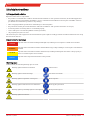
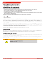
Warning signs
In this manual, the following warning signs are used:
Warning against hazardous situations General notice
Warning against electrical voltage Disconnect from mains
Warning against respiration of toxic gases Wear respirator
Warning against acid and corrosive substances Wear eye/face protection
Warning against potentially explosive atmospheres Wear protection gloves
Warning against hot surface
3Bühler Technologies GmbHBE460013 ◦ 01/2020

ECO
2.2 General hazard warnings
The equipment must be installed by a professional familiar with the safety requirements and risks.
Be sure to observe the safety regulations and generally applicable rules of technology relevant for the installation site. Prevent
malfunctions and avoid personal injuries and property damage.
The operator of the system must ensure:
– Safety notices and operating instructions are available and observed,
– The respective national accident prevention regulations are observed,
– The permissible data and operational conditions are maintained,
– Safety guards are used and mandatory maintenance is performed,
– Legal regulations are observed during disposal,
– compliance with national installation regulations.
Maintenance, Repair
Please note during maintenance and repairs:
– Repairs to the unit must be performed by Bühler authorised personnel.
– Only perform conversion-, maintenance or installation work described in these operating and installation instructions.
– Always use genuine spare parts.
– Do not install damaged or defective spare part. If necessary, visually inspect prior to installation to determine any obvious
damage to the spare parts.
Always observe the applicable safety and operating regulations in the respective country of use when performing any type of
maintenance.
DANGER Electrical voltage
Electrocution hazard.
a) Disconnect the device from power supply.
b) Make sure that the equipment cannot be reconnected to mains unintentionally.
c) The device must be opened by trained staff only.
d) Regard correct mains voltage.
DANGER Toxic, corrosive gases
The measuring gas led through the equipment can be hazardous when breathing or
touching it.
a) Check tightness of the measuring system before putting it into operation.
b) Take care that harmful gases are exhausted to a save place.
c) Before maintenance turn off the gas supply and make sure that it cannot be turned
on unintentionally.
d) Protect yourself during maintenance against toxic / corrosive gases. Use suitable pro-
tective equipment.
DANGER Potentially explosive atmosphere
Explosion hazard if used in hazardous areas.
The device is not suitable for operation in hazardous areas with potentially explosive at-
mospheres.
Do not expose the device to combustible or explosive gas mixtures.
4 Bühler Technologies GmbH BE460013 ◦ 01/2020

ECO
3 Transport and storage
The device should be only transported in the original case or in appropriate packing.
If the device is not used for some time, protect it against heat and humidity. Store the device in a roofed, dry, and dust free
room. Temperature should be between –20 °C and 40 °C (-4 °F and 104 °F).
5Bühler Technologies GmbHBE460013 ◦ 01/2020

ECO
4 Installation and connection
4.1 Installation site requirements
Sample gas probes are intended for flange mounting.
– Installation site and installation position are determined based on requirements specific to the application.
– If necessary, the connection piece should be slightly tilted toward the centre of the channel.
– The installation site should be protected from the weather.
– In addition, adequate and safe access for installation and future maintenance work should be provided. Particularly follow
the uninstalled size of the probe tube!
If the probe is transported to the installation site in pieces, it will first need to be assembled.
4.2 Installation
Sampling tube 03 (sintered stainless steel filter) only needs to be screwed on.
Sampling tubes 10 and 11 need to be screwed in, then covered with filter paper and secured on the flange end with the clamp.
The pressure vessel has two fittings with G ¼" internal thread on the outside. One of these fittings is needed to discharge con-
densate and must point downward. The other can be used to connect a pressure gauge (not included). Unused fittings must be
sealed with a plug.
The pressure vessel can be turned to allow any mounting position of the probe. To do so, unscrew the plug for from the air con-
nection at the back (drawing see data sheet). You will now see the hex nut inside the opening. Loosen this, pull the pressure ves-
sel away from the probe and turn it in the desired direction. Ensure one fitting on the outside points downwards to discharge
condensate. Now tighten the nut again and screw in the plug until tight.
The probe is then attached to the mating flange using the included seals and screws.
4.3 Insulation
On heated probes completely insulate any exposed flange areas and, if applicable, the connection piece to absolutely prevent
thermal bridges. The insulating material must meet the application requirements and be weatherproof.
4.4 Connecting the Gas Line
The sample gas line must be carefully and properly connected using a suitable fitting (NPT ¼"). This also applies to the test gas
connection. If the latter is not being used, seal it with a plug.
To avoid condensation in the line in your application, it will need to be heated. The screw-in connection and the probe must
then be insulated.
WARNING Gas emanation
Sample gas can be harmful to the health!
Check the lines for leaks.
6 Bühler Technologies GmbH BE460013 ◦ 01/2020

ECO
4.5 Electrical connections
WARNING Hazardous electrical voltage
The device must be installed by trained staff only.
CAUTION Wrong mains voltage
Wrong mains voltage may damage the device.
Regard the correct mains voltage as given on the type plate.
Electric strength test
The necessary tests of all assemblies required to be tested were carried out at the factory (test voltage 1 kV or 1.5 kV depending
on component).
To check the electric strength again yourself, only do so on the respective individual components.
– Now perform the electric strength test against earth.
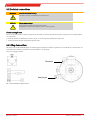
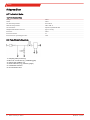
4.5.1 Plug Connection
This device has an EN 175301-803 plug. The following pin assignments and the assignment of solenoid valves to the function are
listed below. The numbers specified correspond with those on the plugs.
The power supply is 24 VDC.
Blowback
Sample gas
Fig.1: A02-100034 pin assignment ECO
7Bühler Technologies GmbHBE460013 ◦ 01/2020

ECO
5 Operation and controls
NOTICE
The device must not be operated beyond its specifications.
5.1 Before Start-Up
Before starting the device, verify
– the hose- and electrical connections are not damaged and correct installed.
– no parts of the gas probe have been removed.
– the safety and monitoring devices are installed and functional.
– the gas inlet and outlet of the gas probe are open.
– ambient parameters are met.
– the performance specifications in the type plate are met.
– voltage and frequency in the type plate match the mains values.
– all connection cables are installed without strain.
– precautions have been taken.
– cable glands are sealed properly.
– the earth is proper and functional.
8 Bühler Technologies GmbH BE460013 ◦ 01/2020

ECO
6 Maintenance
During maintenance, remember:
– The equipment must be maintained by a professional familiar with the safety requirements and risks.
– Only perform maintenance work described in these operating and installation instructions.
– When performing maintenance of any type, observe the respective safety and operation regulations.
DANGER Electrical voltage
Electrocution hazard.
a) Disconnect the device from power supply.
b) Make sure that the equipment cannot be reconnected to mains unintentionally.
c) The device must be opened by trained staff only.
d) Regard correct mains voltage.
DANGER
The gas inside the filter, condensate and used filter elements may be caustic or corros-
ive.
Sample gas can be harmful.
a) Before maintenance turn off the gas supply and surge with air if necessary.
b) Exhaust sample gas to a safe place.
c) Protect yourself against toxic / corrosive gas during maintenance. Wear appropriate
personal protection equipment.
CAUTION Hot surface
Risk of burns
Housing temperatures may be high during operation.
Allow the unit to cool down before performing maintenance.
6.1 Backwashing the Inlet Filter
Be sure to use filtered air with a minimum rating of PNEUROP / ISO Class 4 for blowback:
Class Particles / m
3
Particle size:
(1 to 5) µm
Pressure dew point
[°C]
Residual oil content
[mg / m
3
]
4
to 1000
(no particles ≥ 15 µm)
≤ 3 ≤ 5
The control unit of the system requires sequential valve control, i.e.:
1. closing the solenoid valve for the sample gas outlet.
2. Open the solenoid valve between the pressure vessel and probe for approx. 10 seconds.
3. Open the solenoid valve for the sample gas outlet again.
A delay is required between one solenoid valve closing and the other solenoid valve opening to prevent pressure surges in the
sample gas line.
Blowback can also be set as a closed process at intervals ranging from several minutes to hours or even days based on require-
ments. We offer a type RSS 24 blowback control.
9Bühler Technologies GmbHBE460013 ◦ 01/2020

ECO
7 Service and repair
This chapter contains information on troubleshooting and correction should an error occur during operation.
Repairs to the unit must be performed by Bühler authorised personnel.
Please contact our Service Department with any questions:
Tel.: +49-(0)2102-498955
or your agent
If the equipment is not functioning properly after correcting any malfunctions and switching on the power, it must be inspected
by the manufacturer. Please send the equipment inside suitable packaging to:
Bühler Technologies GmbH
- Reparatur/Service -
Harkortstraße 29
40880 Ratingen
Germany
Please also attach the completed and signed RMA decontamination statement to the packaging. We will otherwise be unable to
process your repair order.
You will find the form in the appendix of these instructions, or simply request it by e-mail:
.
7.1 Troubleshooting
CAUTION Risk due to defective device
Personal injury or damage to property
a) Switch off the device and disconnect it from the mains.
b) Repair the fault immediately. The device should not be turned on again before elim-
ination of the failure.
Problem / Malfunction Possible cause Action
No or reduced gas flow – Filter element clogged – Clean or replace filter element
– Solenoid valve closed – Open solenoid valve
– Blowback not responding – Check compressed air supply
Tab.1: Troubleshooting
7.2 Spare Parts and Accessories
Please also specify the model and serial number when ordering parts.
Upgrade and expansion parts can be found in our catalog.
Available spare parts:
Item no. Description
90 090 79 Flange seal type 222.
90 090 68 Probe tube seal type 222.
46 222 007 1 Replacement filter up to 135 °C, polyester
46 222 007 2 Replacement filter up to 260 °C, PTFE
90 09 081 O-ring for pressure vessel
90 09 053 Cu sealing ring for pressure vessel
10 Bühler Technologies GmbH BE460013 ◦ 01/2020

ECO
8 Disposal
Dispose of parts so as not to endanger the health or environment. Follow the laws in the country of use for disposing of elec-
tronic components and devices during disposal.
11Bühler Technologies GmbHBE460013 ◦ 01/2020

ECO
9 Appendices
9.1 Technical Data
Gas Probe Technical Data
Flange: 1.4571
Head: 1.4571
Gas inlet temperature: max. 120 °C
Ambient temperature: -20 to +60 °C
Solenoid valve: VA/ Viton/ EPDM 24 VDC
Weight without filter element: approx. 9.3 kg
Reservoir: 1.4571
Reservoir volume: 2 L
Reservoir max. operating pressure: 5 bar
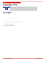
9.2 Functional diagram
1= sampling tube (accessory)
2= NPT 1/4" connection (e.g. calibrating gas)
3= sample gas Off NPT 1/4"
4= G1/4 connector (e.g. pressure gauge)
5= condensate Off G1/4
6= air connection G1/4
12 Bühler Technologies GmbH BE460013 ◦ 01/2020

ECO
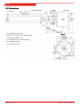
9.3 Dimensions
1= sampling tube (accessory)
2= NPT 1/4" connection (e.g. calibrating gas)
3= sample gas Off NPT 1/4"
4= G1/4 connector (e.g. pressure gauge)
5= condensate Off G1/4
6= air connection G1/4
Accessories
Flange DN65 PN6
Reservoir:
View A
approx. 392 (15.4)
13Bühler Technologies GmbHBE460013 ◦ 01/2020

ECO
10 Attached Documents
– Declaration of Conformity KX460003
– RMA - Decontamination Statement
14 Bühler Technologies GmbH BE460013 ◦ 01/2020


RMA-Nr./ RMA-No.
Die RMA-Nummer bekommen Sie von Ihrem Ansprechpartner im Vertrieb oder Service./ You may obtain the RMA
number from your sales or service representative.
Firma/ Company
Firma/ Company
Straße/ Street
PLZ, Ort/ Zip, City
Land/ Country
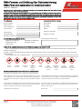
Zu diesem Rücksendeschein gehört eine Dekontaminierungserklärung. Die gesetzlichen Vorschriften schreiben vor,
dass Sie uns diese Dekontaminierungserklärung ausgefüllt und unterschrieben zurücksenden müssen. Bitte füllen Sie
auch diese im Sinne der Gesundheit unserer Mitarbeiter vollständig aus./ This return form includes a decontamination
statement. The law requires you to submit this completed and signed decontamination statement to us. Please com-
plete the entire form, also in the interest of our employee health.
Ansprechpartner/ Person in charge
Name/ Name
Abt./ Dept.
Tel./ Phone
E-Mail
Gerät/ Device
Anzahl/ Quantity
Auftragsnr./ Order No.
Serien-Nr./ Serial No.
Artikel-Nr./ Item No.
Grund der Rücksendung/ Reason for return
Kalibrierung/ Calibration Modifikation/ Modification
Reklamation/ Claim Reparatur/ Repair
andere/ other
bitte spezifizieren/ please specify
Ist das Gerät möglicherweise kontaminiert?/ Could the equipment be contaminated?
Nein, da das Gerät nicht mit gesundheitsgefährdenden Stoffen betrieben wurde./ No, because the device was not operated with
hazardous substances.
Nein, da das Gerät ordnungsgemäß gereinigt und dekontaminiert wurde./ No, because the device has been properly cleaned and
decontaminated.
Ja, kontaminiert mit:/ Yes, contaminated with:
explosiv/
explosive
entzündlich/
flammable
brandfördernd/
oxidizing
komprimierte
Gase/
compressed
gases
ätzend/
caustic
giftig,
Lebensgefahr/
poisonous, risk
of death
gesundheitsge-
fährdend/
harmful to
health
gesund-
heitsschädlich/
health hazard
umweltge-
fährdend/
environmental
hazard
Bitte Sicherheitsdatenblatt beilegen!/ Please enclose safety data sheet!
Das Gerät wurde gespült mit:/ The equipment was purged with:
Diese Erklärung wurde korrekt und vollständig ausgefüllt und von einer
dazu befugten Person unterschrieben. Der Versand der (dekontaminier-
ten) Geräte und Komponenten erfolgt gemäß den gesetzlichen Bestim-
mungen.
This declaration has been filled out correctly and completely, and signed by
an authorized person. The dispatch of the (decontaminated) devices and
components takes place according to the legal regulations.
Datum/ Date
rechtsverbindliche Unterschrift/ Legally binding signature
Falls die Ware nicht gereinigt, also kontaminiert bei uns eintrifft, muss die
Firma Bühler sich vorbehalten, diese durch einen externen Dienstleister
reinigen zu lassen und Ihnen dies in Rechnung zu stellen.
Should the goods not arrive clean, but contaminated, Bühler reserves the
right, to comission an external service provider to clean the goods and in-
voice it to your account.
Firmenstempel/ Company Sign
DE000011
01/2019
RMA-Formular und Erklärung über Dekontaminierung
RMA-Form and explanation for decontamination
Bühler Technologies GmbH, Harkortstr. 29, D-40880 Ratingen
Tel. +49 (0) 21 02 / 49 89-0, Fax: +49 (0) 21 02 / 49 89-20
E-Mail: [email protected]
Internet: www.buehler-technologies.com

Dekontaminierungserklärung
Die Analyse defekter Baugruppen ist ein wesentlicher Bestandteil der Qualitätssicherung der Firma
Bühler Technologies.
Um eine aussagekräftige Analyse zu gewährleisten muss die Ware möglichst unverändert untersucht
werden. Es dürfen keine Veränderungen oder weitere Beschädigungen auftreten, die Ursachen ver-
decken oder eine Analyse unmöglich machen.
Bei elektronischen Baugruppen kann es sich um elektrostatisch sensible Baugruppen handeln. Es ist
darauf zu achten, diese Baugruppen ESD-gerecht zu behandeln. Nach Möglichkeit sollten die Baugrup-
pen an einem ESD-gerechten Arbeitsplatz getauscht werden. Ist dies nicht möglich sollten ESD-
gerechte Maßnahmen beim Austausch getroffen werden. Der Transport darf nur in ESD-gerechten Be-
hältnissen durchgeführt werden. Die Verpackung der Baugruppen muss ESD-konform sein. Verwenden
Sie nach Möglichkeit die Verpackung des Ersatzteils oder wählen Sie selber eine ESD-gerechte Ver-
packung.
Beachten Sie beim Einbau des Ersatzteils die gleichen Vorgaben wie oben beschrieben. Achten Sie auf
die ordnungsgemäße Montage des Bauteils und aller Komponenten. Versetzen Sie vor der Inbetrieb-
nahme die Verkabelung wieder in den ursprünglichen Zustand. Fragen Sie im Zweifel beim Hersteller
nach weiteren Informationen.
Analysing defective assemblies is an essential part of quality assurance at Bühler Technologies.
To ensure conclusive analysis the goods must be inspected unaltered, if possible. Modifications or
other damages which may hide the cause or render it impossible to analyse are prohibited.
Electronic assemblies may be sensitive to static electricity. Be sure to handle these assemblies in an
ESD-safe manner. Where possible, the assembles should be replaced in an ESD-safe location. If un-
able to do so, take ESD-safe precautions when replacing these. Must be transported in ESD-safe con-
tainers. The packaging of the assemblies must be ESD-safe. If possible, use the packaging of the spare
part or use ESD-safe packaging.
Observe the above specifications when installing the spare part. Ensure the part and all components
are properly installed. Return the cables to the original state before putting into service. When in doubt,
contact the manufacturer for additional information.
DE000011
01/2019
Bühler Technologies GmbH, Harkortstr. 29, D-40880 Ratingen
Tel. +49 (0) 21 02 / 49 89-0, Fax: +49 (0) 21 02 / 49 89-20
E-Mail: [email protected]
Internet: www.buehler-technologies.com
-
 1
1
-
 2
2
-
 3
3
-
 4
4
-
 5
5
-
 6
6
-
 7
7
-
 8
8
-
 9
9
-
 10
10
-
 11
11
-
 12
12
-
 13
13
-
 14
14
-
 15
15
-
 16
16
-
 17
17
-
 18
18
-
 19
19


Buhler Eco Installation And Operation Instructions Manual
- Typ
- Installation And Operation Instructions Manual
- Dieses Handbuch eignet sich auch für
in anderen Sprachen
- English: Buhler Eco
Verwandte Artikel
-
Buhler GAS 222.31 Ex2 Installation And Operation Instructions Manual
-
Buhler GAS 222.21 AMEX Installation And Operation Instructions Manual
-
-
-
-
-
-
-
-
