
Analysentechnik
Installation and Operation Instructions
Original instructions
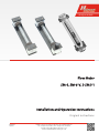
Flow Meter
SM-6, SM-6-V, S-SM 3-1
BE400001
11/2016
Bühler Technologies GmbH, Harkortstr. 29, D-40880 Ratingen
Tel. +49 (0) 21 02 / 49 89-0, Fax: +49 (0) 21 02 / 49 89-20
E-Mail: [email protected]
Internet: www.buehler-technologies.com

Bühler Technologies GmbH, Harkortstr. 29, D-40880 Ratingen
Tel. +49 (0) 21 02 / 49 89-0, Fax: +49 (0) 21 02 / 49 89-20
Internet: www.buehler-technologies.com
E-Mail: [email protected]
Read this instruction carefully prior to installation and/or use. Pay at-
tention particularly to all advises and safety instructions to prevent in-
juries. Bühler Technologies can not be held responsible for misusing
the product or unreliable function due to unauthorised modifications.
All rights reserved. Bühler Technologies GmbH 2017
Document information
Document No......................................................... BE400001
Version...........................................................................11/2016

SM-6, SM-6-V, S-
SM 3-1
Contents
1 Introduction..................................................................................................................................................................................................................... 2
1.1 Intended use .........................................................................................................................................................................................................2
1.2 Contents................................................................................................................................................................................................................. 2
1.3 Ordering instructions ........................................................................................................................................................................................ 3
2 Safety instructions.........................................................................................................................................................................................................4
2.1 Important advice .................................................................................................................................................................................................4
2.2 General hazard warnings .................................................................................................................................................................................4
3 Transport and storage ..................................................................................................................................................................................................6
4 Installation and connection ........................................................................................................................................................................................ 7
4.1 Mounting a flow sensor with brackets (type SM-6 / SM-6-V only)....................................................................................................... 7
5 Operation and control ..................................................................................................................................................................................................8
5.1 Read the flow value ............................................................................................................................................................................................8
5.2 Adjusting the needle valve ...............................................................................................................................................................................8
6 Maintenance....................................................................................................................................................................................................................9
6.1 Replacing the flow sensor with brackets (type SM-6 / SM-6-V only) ...................................................................................................9
6.2 Replacing the metering tube (type SM-6 / SM-6V only)......................................................................................................................... 11
6.2.1 Without flow sensor ...........................................................................................................................................................................11
6.2.2 With flow sensor..................................................................................................................................................................................11
6.3 Replacing the metering tube - Safety flow meters S-SM........................................................................................................................ 11
7 Service and repair..........................................................................................................................................................................................................12
7.1 Troubleshooting ................................................................................................................................................................................................ 12
7.2 Spare parts and accessories ........................................................................................................................................................................... 12
7.2.1 Spare parts and accessories - S-SM ...............................................................................................................................................12
7.2.2 Spare parts and accessories - switch amplifier..........................................................................................................................12
8 Disposal............................................................................................................................................................................................................................13
9 Appendices..................................................................................................................................................................................................................... 14
9.1 Technical Data.................................................................................................................................................................................................... 14
9.2 Dimensions ..........................................................................................................................................................................................................15
9.3 Measuring ranges ............................................................................................................................................................................................. 16
10 Attached documents................................................................................................................................................................................................... 18
iBühler Technologies GmbHBE400001 ◦ 11/2016

SM-6, SM-6-V, S-
SM 3-1
1 Introduction
1.1 Intended use
The flow meter can be used to display flow volumes of sample gasses or liquid mediums. Please refer to the nameplate to
identify your model. In addition to the job number it also contains the item number and model designation. Any special fea-
tures applicable to a flow meter model are described separately in the operating manual. When connecting, please note the spe-
cific values of the flow meter, and the correct version when ordering spare parts.
SM-6/SM-6-V series flow meters can also be equipped with a bistable limit switch. On the SM-6-V the flow volume can be adjus-
ted with the needle valve.
On S-SM series safety flow meters the actual metering glass is protected by a second, thick-walled glass cylinder. If the metering
glass bursts, the outer glass cylinder resumes protecting so medium cannot leak. A stainless steel tube further protects this
outer glass cylinder from mechanical damage. Please refer to the data sheet for the various S-SM models.
NOTICE When used in explosive areas
Model SM-6, SM6-V and S-SM 3-1 flow meters meet the fundamental safety require-
ments of Directive 2014/34/EU and are therefore suitable for use in Ex areas (
Zone 1, Ex-
plosion Group IIC
, hazard notes must be observed).
Explosion group IIB
(model SM-6 and
SM-6-V)
or IIC
(model S-SM 3-1) non-flammable and flammable gasses which may occa-
sionally be explosive during normal operation may be conveyed through the needle
valves (
Zone 1
). The type plate on the flow meters has no Ex classification, as the medi-
ums have no own ignition sources and therefore do not fall under Directive 2014/34/EU.
1.2 Contents
– 1 x Flow meter
– 1 x Product documentation
– 1 x Bracket (Model SM-6 / SM-6-V only)
2 Bühler Technologies GmbH BE400001 ◦ 11/2016

SM-6, SM-6-V, S-
SM 3-1
1.3 Ordering instructions
The item number is a code for the configuration of your unit. Please use the following model key:
4056 X X X 99 X Measuring range*
0 0 Air 6 - 60 Nl/h
0 1 Air 10 - 100 Nl/h
0 2 Air 25 - 250 Nl/h
0 3 Air 50 - 500 Nl/h
0 4 Air 80 - 800 Nl/h
0 5 Water 0.5 - 5 L/h
0 6 Water 1.2 - 12 L/h
0 7 Water 2.5 - 25 L/h
0 8 Water 4 - 40 L/h
0 9 Water 6 - 60 L/h
1 0 Special range
0 without needle valve
1 Valve PVDF / Viton
2 Valve PCTFE / perfluorelastomer
S Limit switch with mounting bracket
- without limit switch
* Standard measuring tubes; air 20 °C 1.2 bar abs; water 20 °C
Ordering information for limit switch:
A limit switch is factory installed if the last character of the item number is "S". Without
the "S" marking the flow meter has no limit switch. We offer various switch amplifiers for controlling the limit switch (see data
sheet no. 400003).
3Bühler Technologies GmbHBE400001 ◦ 11/2016

SM-6, SM-6-V, S-
SM 3-1
2 Safety instructions
2.1 Important advice
Operation of the device is only valid if:
– the product is used under the conditions described in the installation- and operation instruction, the intended application
according to the type plate and the intended use. In case of unauthorized modifications done by the user Bühler Technolo-
gies GmbH can not be held responsible for any damage,
– when complying with the specifications and markings on the nameplates.
– the performance limits given in the datasheets and in the installation- and operation instruction are obeyed,
– monitoring devices and safety devices are installed properly,
– service and repair is carried out by Bühler Technologies GmbH,
– only original spare parts are used.
This manual is part of the equipment. The manufacturer keeps the right to modify specifications without advanced notice. Keep
this manual for later use.
Signal words for warnings
DANGER
Signal word for an imminent danger with high risk, resulting in severe injuries or death if not avoided.
WARNING
Signal word for a hazardous situation with medium risk, possibly resulting in severe injuries or death if not
avoided.
CAUTION
Signal word for a hazardous situation with low risk, resulting in damaged to the device or the property or
minor or medium injuries if not avoided.
NOTICE
Signal word for important information to the product.
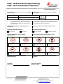
Warning signs
These instructions use the following warning signs:
Warns of a general hazard Wear respiratory equipment
Warns not to inhale toxic gasses Wear a safety mask
Warns of corrosive liquids Wear gloves
Warns of explosive areas
2.2 General hazard warnings
The equipment must be installed by a professional familiar with the safety requirements and risks.
Be sure to observe the safety regulations and generally applicable rules of technology relevant for the installation site. Prevent
malfunctions and avoid personal injuries and property damage.
4 Bühler Technologies GmbH BE400001 ◦ 11/2016

SM-6, SM-6-V, S-
SM 3-1
The operator of the system must ensure:
– Safety notices and operating instructions are available and observed,
– Inspections prior to initial operation and routine inspections according to the Ordinance on Industrial Safety and Health (Be-
trSichV) are performed,
– The respective national accident prevention regulations are observed,
– The permissible data and operational conditions are maintained,
– Safety guards are used and mandatory maintenance is performed,
– Legal regulations are observed during disposal.
Maintenance, Repair
Please note during maintenance and repairs:
– Repairs to the unit must be performed by Bühler authorised personnel.
– Only perform conversion-, maintenance or installation work described in these operating and installation instructions.
– Always use genuine spare parts.
Always observe the applicable safety and operating regulations in the respective country of use when performing any type of
maintenance.
DANGER Toxic, acidic gasses
Sample gas can be harmful.
a) Switch off the gas supply before performing maintenance and, if necessary, flush the
gas lines with air.
b) If necessary, ensure a safe gas discharge.
c) Protect yourself from toxic / acidic gasses when performing maintenance. Wear ap-
propriate protective equipment.
NOTICE When used in explosive areas
Model SM-6, SM6-V and S-SM 3-1 flow meters meet the fundamental safety require-
ments of Directive 2014/34/EU and are therefore suitable for use in Ex areas (
Zone 1, Ex-
plosion Group IIC
, hazard notes must be observed).
Explosion group IIB
(model SM-6 and
SM-6-V)
or IIC
(model S-SM 3-1) non-flammable and flammable gasses which may occa-
sionally be explosive during normal operation may be conveyed through the needle
valves (
Zone 1
). The type plate on the flow meters has no Ex classification, as the medi-
ums have no own ignition sources and therefore do not fall under Directive 2014/34/EU.
DANGER Application in explosive atmosphere
Combustible gases and dust may inflame or explode. Avoid the following hazardous
situations:
Electrostatic charge (spark formation)!
Clean plastic parts and labels with damp cloth only.
Connect metallic housings to ground!
Maximum surface temperature!
The maximum surface temperature T
surf
of the equipment corresponds to the medium-
temperature T
med
; T
surf
≤ T
med
.
Ignition temperature!
Regard the ignition temperature of the explosive gas-atmosphere as well as maximum
allowable surface temperatures (regard directive 94/9/ EC and harmonized standards).
Risk of breakage / emission of explosive or toxic gas possible.
Protect the equipment against being hit.
Gas leakage!
Life and explosion risk may result from gas leakage due to improper use or during main-
tenance.
5Bühler Technologies GmbHBE400001 ◦ 11/2016

SM-6, SM-6-V, S-
SM 3-1
3 Transport and storage
The product should only be transported inside the original packaging or a suitable alternative.
When not in use, the equipment must be protected from moisture and heat. They must be stored in a covered, dry and dust-free
room at a temperature between -10 °C and 40 °C.
6 Bühler Technologies GmbH BE400001 ◦ 11/2016

SM-6, SM-6-V, S-
SM 3-1
4 Installation and connection
The flow meters are equipped with the following threads:
Flow meter Thread
SM-6 / SM-6-V G 1/4
S-SM 3-1 NPT 1/4”
Please refer to chapter Dimensions [> page15] for the assembly drawing. The fittings must be screwed in tight, sealed with Te-
flon tape or sealant/flat gasket!
4.1 Mounting a flow sensor with brackets (type SM-6 / SM-6-V only)
DANGER Explosion hazard
Application in explosive atmosphere
Only use certificated flow sensors.
The limit switch is preinstalled.
– Prior to first use, loosen the plastic countersunk screws from the mounting plate and position the limit switch at the desired
height.
– The Plastic countersunk screws must be fastened again.
– Connect the cable to the power supply.
– Using the limit switch in Ex areas: Please note the wiring parameters! We recommend a selection of switch amplifiers, also
see data sheet no. 400003.
7Bühler Technologies GmbHBE400001 ◦ 11/2016

SM-6, SM-6-V, S-
SM 3-1
5 Operation and control
NOTICE
The device must not be operated beyond its specifications.
5.1 Read the flow value
The flow value can be read at the top of the float.
Please note: The values can only be correct, if the medium and pressure specified on the type plate match the sample.
5.2 Adjusting the needle valve
NOTICE!Please note: The needle valve is NOT a shut-off valve. Do not force the valve.
The valve is closed turning clockwise.
8 Bühler Technologies GmbH BE400001 ◦ 11/2016

SM-6, SM-6-V, S-
SM 3-1
6 Maintenance
During maintenance, remember:
– The equipment must be maintained by a professional familiar with the safety requirements and risks.
– Only perform maintenance work described in these operating and installation instructions.
– When performing maintenance of any type, observe the respective safety and operation regulations.
DANGER Explosion hazard
Gas leakage
If explosive, toxic or corrosive gas (liquid) will lead through the flow meter, check the leak
tightness at regular intervals.
DANGER Toxic, corrosive gasses
Sample gas can be harmful.
a) Switch off the process (depressurise) before starting maintenance. To do so, close the
shut-off valve (if applicable).
b) Flush the flow meter with air before opening.
c) Protect yourself from toxic / corrosive gasses when performing maintenance. Wear
appropriate protective equipment.
CAUTION Gas leakage
Don’t use damaged parts again.
Only use original spare parts.
6.1 Replacing the flow sensor with brackets (type SM-6 / SM-6-V only)
DANGER Explosion hazard
Application in explosive atmosphere
Only use certificated flow sensors.
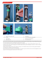
Remove the plastic countersunk screws (1) from the limit switch mounting plate (see Fig. 1). This will also loosen the clamping
plate at the back of the flow meter.
Loosen both swivel nuts on the measuring tube. Slide the measuring tube into the upper end piece, applying light pressure. You
can now swing out the measuring tube (see Fig. 2). Remove the gasket (2), die swivel nut (3) and limit switch (4) at the bottom
end of the measuring tube. The measuring tube may be cleaned if necessary.
Measuring tubes with limit switch are assembled in the reverse order. Please be sure the chamfer on the gasket faces the re-
spective end piece.
9Bühler Technologies GmbHBE400001 ◦ 11/2016

SM-6, SM-6-V, S-
SM 3-1
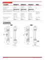
Fig. 1 Fig. 2
1
2
3
4
Fig. 3
Fig. 4
6
7
8
5
Fig. 5
1 Plastic countersunk screws 3 Swivel nut
2 Gasket 4 Limit switch with mounting plate
5 Limit switch 7 Machined mounting plate
6 M3 square nuts 8 Cross-head screws
Loosen both cross-head screws (8) on the mounting plate for the limit switch (see Fig. 4). Remove the mounting plate (7). Be care-
ful not to lose the two square nuts (6) in the slots on the limit switch! Replace the limit switch (5) and fasten the mounting plate.
The machined chamfer on the mounting plate (7) must face the top left.
You can now slide the limit switch onto the measuring tube again. When doing so, please note the direction of flow, i.e. the
markings must be visible, the mounting plate for the limit switch must be positioned with the screw holes over the slot and the
cable is fed out the bottom.
Finally, slide the swivel nut and the gasket (with the sealing cone toward the bracket) onto the measuring tube. Reinstall the
measuring tube and tighten the swivel nut by hand.
Now insert the plastic countersunk screws through the slot in the base plate of the flow meter to fasten and adjust the mount-
ing plate to the clamping plate inside the back of the base plate.
10 Bühler Technologies GmbH BE400001 ◦ 11/2016

SM-6, SM-6-V, S-
SM 3-1
6.2 Replacing the metering tube (type SM-6 / SM-6V only)
6.2.1 Without flow sensor
Loosen the two swivel nuts for the measuring tube. Slide the metering tube into the upper end piece, applying light pressure.
You can now move the gaskets under the swivel nuts onto the tapered end of the metering tube. You can now swing out the
measuring tube.
You can now remove the swivel nuts and gaskets from the measuring tube and, if necessary, move them onto the new measur-
ing tube. The metering tube is assembled in the reverse order. Please be sure the chamfer on the gasket faces the respective end
piece.
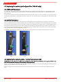
6.2.2 With flow sensor
Loosen the top plastic countersunk screw (1) from the mounting plate for the limit switch (see Fig. I) and loosen the bottom
plastic countersunk screw (1) so the limit switch can be moved. Removing it completely from the mounting plate is not required.
Loosen the two swivel nuts (3) for the measuring tube. Slide the metering tube into the upper end piece, applying light pressure.
Turn the limit switch to the side (see Fig. 6) when pulling the metering tube out of the limit switch as well as the swivel nut. If
necessary, move the limit switch in the process. Remove the gasket (2) and the swivel nut (3) at the bottom of the metering tube.
Leave the limit switch on the mounting plate (see Fig. 7).
Assemble the measuring tube in the reverse order. Please be sure the chamfer on the gasket faces the respective end piece.
Fig. 6 Fig. 7
6.3 Replacing the metering tube - Safety flow meters S-SM
NOTICE!This procedure has to be carried out very carefully. You should only do it yourself, if you are sure, you are able to cope
with it. We recommend sending the flow meter back to the manufacturer.
Screw one of the end pieces out of the flow meter while holding the flow meter in a direction preventing the metering tube from
slipping out. The metering tube can now be taken out.
When mounting the new metering tube the metering and the protection glass has to fit correctly into the O-rings and end
pieces.
11Bühler Technologies GmbHBE400001 ◦ 11/2016

SM-6, SM-6-V, S-
SM 3-1
7 Service and repair
This chapter contains information on troubleshooting and correction should an error occur during operation.
Repairs to the unit must be performed by Bühler authorised personnel.
Please contact our Service Department with any questions:
Tel.: +49-(0)2102-498955
or your agent
If the equipment is not functioning properly after correcting any malfunctions and switching on the power, it must be inspected
by the manufacturer. Please send the equipment inside suitable packaging to:
Bühler Technologies GmbH
- Reparatur/Service -
Harkortstraße 29
40880 Ratingen
Germany
Please also attached the completed and signed RMA decontamination statement to the packaging. We will otherwise be unable
to process your repair order.
You will find the form in the appendix of these instructions, or simply request it by e-mail:
.
7.1 Troubleshooting
Problem / Failure Possible cause Solution
Float doesn’t rise – Needle valve closed – Open needle valve
– Pollution by liquid or particles – Clean metering tube
Tab.1: Troubleshooting
7.2 Spare parts and accessories
Please also specify the model and serial number when ordering parts.
Upgrade and expansion parts can be found in our catalog.
Available spare parts:
Item no. Description
40 15 89 97 Gasket for Ø 10 mm tube diameter
40 55 05 0 Gasket for Ø 15 mm tube diameter
7.2.1 Spare parts and accessories - S-SM
Item no. Description
40 22 999 Flow Meter S-SM 3-1 End sections stainless steel 1.4571
40 23 999 Flow Meter S-SM 3-1 End sections titanium
7.2.2 Spare parts and accessories - switch amplifier
Item no. Description
91 000 700 04 Switch amplifier, KFD2-SR2-Ex 1.W, 24 V DC
91 000 700 05 Switch amplifier, KFA5-SR2-Ex 1.W, 115 V AC
91 000 700 06 Switch amplifier, KFA6-SR2-Ex 1.W, 230 V AC
91 000 700 07 Switch amplifier, KCD2-E2L, 24 V DC
49 490 21 Limit switch with mounting bracket Ø10
49 490 19 Limit switch with mounting bracket Ø15
12 Bühler Technologies GmbH BE400001 ◦ 11/2016

SM-6, SM-6-V, S-
SM 3-1
8 Disposal
Dispose of parts so as not to endanger the health or environment. Follow the laws in the country of use for disposing of elec-
tronic components and devices during disposal.
13Bühler Technologies GmbHBE400001 ◦ 11/2016

SM-6, SM-6-V, S-
SM 3-1
9 Appendices
9.1 Technical Data
Flow meter SM-6, SM-6-V
Ambient temperature: -20 °C to +80 °C *
Medium temperature: ≤ 150 °C, for special ranges max. 80 °C
Operating pressure max. 4 bar
Material
Heads: PTFE
Seal: PTFE
Adjusting spindle: PVDF / Viton or PCTFE / perfluoroelastomer
Measuring tube: Borosilicate glass
Float: Hastelloy C 4 or optional
PEEK with soft iron core
Swivel nut: PPS fibreglass reinforced
Base plate: PA
* Please note the ambient temperature for the configuration with limit switch!
Limit switch Ø10 Ø15
Protection class: IP 67 IP 67
Ambient temperature: -20 °C to +100 °C -20 °C to +70 °C
Housing material: PBT PBT
Operation: bi-stable bi-stable
Cord length: 2 m 2 m
Approval: PTB 99 ATEX 2128X
II 2 G Ex ia II C T6…T1 Gb
PTB 99 ATEX 2128X
II 2 G Ex ia II C T6…T1 Gb
Safety Flow Meter S-SM 3-1
Ambient temperature: -20 °C to 80 °C *
Operating pressure: 10 bar (at max. 20 °C) **
Operating temperature: 100 °C (at max. 2 bar) **
Measuring range: see table
Weight: 0.9 kg
Float: glass, Hastelloy, stainless steel or PTFE
End sections: PTFE, stainless steel or titanium
Mounting: via included pipe clamps
* specify in order, select mounting.
10
** Max. operating pressure [bar] = 10 -
Max. operating temperature [°C] - 20
14 Bühler Technologies GmbH BE400001 ◦ 11/2016

SM-6, SM-6-V, S-
SM 3-1
Switch amplifier KFD2-SR2-Ex 1.W KFA5-SR2-Ex 1.W KFA6-SR2-Ex 1.W KCD2-E2L
Supply voltage: 20 - 30 V DC 103.5 - 126 V AC
45 - 65 Hz
207 - 253 V AC
45 - 65 Hz
10 - 30 V DC
Inherently safe per: EN 60079-11 EN 60079-11 EN 60079-11 no
Line monitor: yes yes yes yes
Approvals:
(FM, UL, CSA, IECEx in accordance
with the operating instructions)
PTB 00 ATEX 2080
II(1)G [Ex ia Ga] IIC
PTB 00 ATEX 2081
II(1)G [Ex ia Ga] IIC
PTB 00 ATEX 2081
II(1)G [Ex ia Ga] IIC
Output (not inherently safe): Change-over contact Change-over contact Change-over contact NO contact
PNP transistor
Switching current output: 230 V AC, 2 A
cos φ > 0.7
40 V DC, 2 A
ohmic load
230 V AC, 2 A
cos φ > 0.7
40 V DC, 2 A
ohmic load
230 V AC, 2 A
cos φ > 0.7
40 V DC, 2 A
ohmic load
200 mA DC
Ambient temperature: -20 °C ...+60 °C -20 °C ...+60 °C -20 °C ...+60 °C -25 °C ...+70 °C
Protection class: IP 20 IP 20 IP 20 IP 20
Dimensions: 20x119x115 mm
(WxHxD)
20x119x115 mm
(WxHxD)
20x119x115 mm
(WxHxD)
20x63x44 mm
(WxHxD)
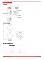
9.2 Dimensions
SM6 / SM6-V flow meter:
SM-6 SM-6-V
max.
15Bühler Technologies GmbHBE400001 ◦ 11/2016

SM-6, SM-6-V, S-
SM 3-1
Limit switch:
Locking screw
Limit switch
Locking screw
Switching point
7
34
20
S-SM safety flow meter:
9.3 Measuring ranges
SM-6 flow meter
Medium: Air Water
Pressure: + 1.2 bar abs.
Temperature: + 20 °C + 20 °C
6 … 60 Nl/h 0.5 … 5 L/h
10 … 100 Nl/h 1.2 … 12 L/h
25 … 250 Nl/h 2.5 … 25 L/h
50 … 500 Nl/h 4 … 40 L/h
80 … 800 Nl/h 6 … 60 L/h
16 Bühler Technologies GmbH BE400001 ◦ 11/2016

SM-6, SM-6-V, S-
SM 3-1
Flow Meter S-SM 3-1
Medium: Air Water
Pressure: + 1.2 bar abs.
Temperature: + 20 °C + 20 °C
1.6 – 16 Nl/h 0.25 - 2.5 l/h
4 – 40 Nl/h 0.5 - 5 l/h
6 - 60 Nl/h 1.2 - 12 l/h
10 – 100 Nl/h 2.5 - 25 l/h
25 – 250 Nl/h 4 - 40 l/h
50 – 500 Nl/h 6 - 60 l/h
80 – 800 Nl/h 10 - 100 l/h
17Bühler Technologies GmbHBE400001 ◦ 11/2016

SM-6, SM-6-V, S-
SM 3-1
10 Attached documents
– Manufacturer Declaration HX 40 0001
– RMA - Decontamination Statement
18 Bühler Technologies GmbH BE400001 ◦ 11/2016
Seite laden ...
Seite laden ...
Seite laden ...
-
 1
1
-
 2
2
-
 3
3
-
 4
4
-
 5
5
-
 6
6
-
 7
7
-
 8
8
-
 9
9
-
 10
10
-
 11
11
-
 12
12
-
 13
13
-
 14
14
-
 15
15
-
 16
16
-
 17
17
-
 18
18
-
 19
19
-
 20
20
-
 21
21
-
 22
22
-
 23
23


Buhler SM-6-V Installation And Operation Instructions Manual
- Typ
- Installation And Operation Instructions Manual
in anderen Sprachen
- English: Buhler SM-6-V
Verwandte Papiere
-
Buhler Eco Installation And Operation Instructions Manual
-
-
Buhler GAS 222.31 Ex2 Installation And Operation Instructions Manual
-
-
-
-
-
-
-

