GCE SWITCH OVER MANIFOLD Bedienungsanleitung
- Typ
- Bedienungsanleitung

INSTRUCTION FOR USE
GEBRAUCHSANLEITUNG
GCE CENTRAL GAS SYSTEMS
SWITCH OVER MANIFOLD FOR TWO CYLINDERS
UMSCHALTSTATIONEN FÜR ZWEI GASFLASCHEN
EN
DE
M MANIFOLD | T TEC | L LOW FLOW
If you've got your smartphone at hand,
you can simply use the QR code to visit
our DruvaTEC website for more informa-
tion, all documents as downloads and our
product configurator!
MTLM – Manual switch over
MTLS – Semi automatic switch over

CONTENT
1 GENERAL .........................................................................................................................4
1.1 Information about these instruction ............................................................................................................................. 4
1.2 Information about this switch over manifold .............................................................................................................4
1.3 Explanation of symbols ................................................................................................................................................... 4
1.4 Limitation of liability .........................................................................................................................................................5
1.5 Copyright ............................................................................................................................................................................5
1.6 Spare Parts ......................................................................................................................................................................... 5
1.7 Warranty Provision ...........................................................................................................................................................6
1.8 Kundenservice ...................................................................................................................................................................6
2 SAFETY ............................................................................................................................6
2.1 Intended use ......................................................................................................................................................................6
2.1.1 Structural changes at the gas supply panel .............................................................................................................6
2.2 Fundamental risks ...........................................................................................................................................................6
2.3 Operator’s responsibility ................................................................................................................................................ 8
2.4 Personnel requirements .................................................................................................................................................8
2.4.1 Qualifications .................................................................................................................................................................. 8
2.4.2 Unauthorized personnel .............................................................................................................................................9
2.4.3 Training ............................................................................................................................................................................9
2.5 Personal protective equipment ....................................................................................................................................9
2.6 Behavior in case of fire or accident .......................................................................................................................... 10
2.7 Environmental protection ............................................................................................................................................. 10
2.8 Signage ............................................................................................................................................................................ 10
2.8.1 Signs that give orders ................................................................................................................................................ 10
2.8.2 Signs indicating bans ................................................................................................................................................ 10
2.8.3 Warning signs .............................................................................................................................................................. 10
3 TECHNICAL SPECIFICATIONS ...................................................................................11
3.1 Dimension sheet MTLM ..................................................................................................................................................11
3.2 Dimension sheet MTLS ..................................................................................................................................................11
3.3 General information .........................................................................................................................................................11
3.4 Connection values ..........................................................................................................................................................12
3.5 Performance value .........................................................................................................................................................12
3.6 Operating conditions .....................................................................................................................................................12
4 SETUP AND FUNCTION ............................................................................................ 13
4.1 Overview MTLM without inert gas purging ..............................................................................................................13
4.2 Overview MTLM with inert gas purging .....................................................................................................................13
4.3 Overview MTLS without inert gas purging ...............................................................................................................14
4.4 Overview MTLS with inert gas purging .....................................................................................................................14
4.5 Brief description MTLM – manual switch over ........................................................................................................15
4.6 Brief description MTLS – semi automatic switch over ..........................................................................................15

3/48
EN
5 TRANSPORT, PACKAGING AND STORAGE ............................................................ 16
5.1 Safety information for transportation .........................................................................................................................16
5.2 Transport inspection ......................................................................................................................................................16
5.3 Packaging .........................................................................................................................................................................16
5.4 Storage ..............................................................................................................................................................................16
6 INSTALLATION AND INITIAL STARTUP ................................................................... 17
6.1 Safety notes for installation and initial start-up ........................................................................................................ 17
6.2 Preparation ....................................................................................................................................................................... 17
6.3 Installation .........................................................................................................................................................................17
6.4 Required qualifications for initial start-up and cylinder changing ...................................................................... 17
6.5 Initial Start Up...................................................................................................................................................................18
6.5.1 Inert gas purging (MTLM and MTLS with inert gas purging) .............................................................................19
6.5.2 Fill the process gas tubing with process gas ......................................................................................................19
6.5.3 Change empty gas cylinder......................................................................................................................................19
6.5.4 Taking gas supply panel out of operation .......................................................................................................... 20
6.6 Tests ................................................................................................................................................................................. 20
7 OPERATION ................................................................................................................... 20
8 MAINTENANCE ............................................................................................................ 20
8.1 Safety notes for maintenance ..................................................................................................................................... 20
8.2 Maintenance plan ......................................................................................................................................................... 20
8.3 Maintenance work ..........................................................................................................................................................21
8.3.1 Cleaning ..........................................................................................................................................................................21
8.3.2 Requirements for maintenance ...............................................................................................................................21
8.3.3 Necessary maintenance ............................................................................................................................................21
8.4 Measures following maintenance...............................................................................................................................21
9 TROUBLESHOOTING ...................................................................................................21
9.1 Safety notes for troubleshooting .................................................................................................................................21
10 DISMANTLING AND DISPOSAL ............................................................................... 23
10.1 Safety notes for dismantling and disposal ..............................................................................................................23
10.2 Dismantling ....................................................................................................................................................................23
10.3 Disposal ..........................................................................................................................................................................23

4/48
EN
GENERAL
1.1 INFORMATION ABOUT THIS INSTRUCTIONS MANUAL
These instructions are only intended for use with switch over manifolds product type:
• MTLM – manual switch over manifold
• MTLS – semi automatic switch over manifold
These switch over manifolds are suitable to take gas out of gas cylinders or bundles and reduce the pressure.
Because of switch over function the flow is nearly uninterrupted.
These switch over manifolds were installed as permanently wall assembled.
These instructions enable you to operate the system safely and eciently. These instructions form an integral
part of the system and must always be kept with the system and within easy reach of sta at all times.
Prior to any work, the sta must read these instructions carefully and understand the contents. Observance
of all the safety information and instructions for operation that are contained in these instructions is essential
to ensure work safety.
Local accident prevention regulations and general safety regulations governing the use of the system must
also be observed.
Illustrations in these instructions serve to ensure a basic understanding of the system and may dier from
the actual version.
1.2 INFORMATION ABOUT THIS SWITCH OVER MANIFOLD
Switch over manifolds of this type are only suitable for gases defined as standard gas. The maximum working
pressure is 300 bar.
Standard gases are industrial, inert, flammable and oxidizing gases and/ or their mixtures. Not allowed are the
components for corrosive and/ or toxic gases and/or their mixtures.
It is a single stage switch over manifold with metal diaphragm, created and tested according to ISO7291,
including oxygen shock test.
The MTLM – manual switch over manifold consists of two inlet shut-o valves, one inlet pressure gauge and
one pressure regulator with outlet pressure gauge. At the version with inert gas purge option are two more
outlet purge shut-o valves.
The MTLS – semi automatic switch over manifold consists also of two inlet shut-o valves, one inlet pressure
regulator with inlet pressure gauge on the right side and one inlet pressure regulator with inlet and outlet
pressure gauge. Outlet pressure gauge displays outlet pressure from both sides. At the version with inert gas
purging option are two more outlet purge shut-o valves.
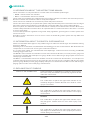
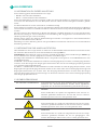
1.3 EXPLANATION OF SYMBOLS
SAFETY INFORMATION Safety information is highlighted by symbols in these instruc-
tions. This safety information is preceded by signal words that
define the extent of risk.
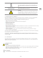
DANGER!
This combination of symbol and signal word indicates an im-
mediately dangerous situation that will cause death or severe
injury if not avoided.
WARNING!
This combination of symbol and signal word indicates a pos-
sibly dangerous situation that can cause death or severe injury
if not avoided.
BEWARE!
This combination of symbol and signal word indicates a pos-
sibly dangerous situation that can cause minor injury if not
avoided.
NOTE!
This combination of symbol and signal word indicates a pos-
sibly dangerous situation that can cause property and environ-
mental damage if not avoided.
1.

5/48
EN
TIPS AND RECOMMENDATIONS
This symbol highlights useful tips and recommendations, to-
gether with help for ensuring ecient and trouble-free opera-
tion.
SPECIAL SAFETY
INFORMATION
The following symbols are used in the safety information to
draw your attention to particular risks.
DANGER!
This combination of symbol and signal word indicates an im-
mediately dangerous situation involving electrical current. Ig-
noring such a warning could result in severe or fatal injuries.
1.4 LIMITATIONS OF LIABILITY
All of the information and notes in these instructions have been compiled in accordance with applicable
standards and regulations. They reflect best engineering practice and our years of experience.
The manufacturer accepts no liability for damages in the following instances:
• Failure to observe these instructions
• Utilization of the system for any other than the intended purpose
• Operation by untrained sta
• Unauthorized modifications
• Technical modifications
• Use of unlicensed spare parts
• Working with the gas supply panel when any safety device is broken or not functional mounted or safety
devices don’t work correctly
• Improper control of components, connections and gaskets, which are wearing parts.
• Incorrect reparations
• Violation of temperature limits, which are dedicated in the datasheet during operation or storage
• In case of disaster or force majeure
The actual scope of supply may dier from the explanations and illustrations in these instructions following
the incorporation of new technical changes.
The obligations stipulated in the supply agreement, our general terms and conditions of business, the
manufacturer’s terms and conditions of supply and the statutory regulations in force at the time of contract
conclusion apply.
1.5 COPYRIGHT
The contents of these instructions are protected by copyright. They may be used in connection with the
operation of the system. Any other use above and beyond the aforementioned is only permitted with the
written consent of the manufacturer.
1.6 SPARE PARTS
WARNING!
• Risk of injury from using incorrect spare parts!
• The use of incorrect or defective spare parts can result in risks for the operating sta and in damages,
malfunctions or total failure of the system.
• Only use original spare parts from the manufacturer or spare parts authorized by the manufacturer.
• Always consult the manufacturer if in doubt.
Loss of warranty
• The manufacturer’s warranty lapses if unauthorized spare parts are used.

6/48
EN
1.7 WARRANTY PROVISION
The warranty provisions are included in the manufacturer’s general terms and conditions of business. See
chapter VI. Warranty Claims.
1.8 CUSTOMER SERVICE
GCE GmbH
Weyherser Weg 8
36043 Fulda
Please do not hesitate to provide us with information and experiences gained through use; we welcome any
valuable input that will help to improve our products.
SAFETY
This section provides an overview of all the important safety aspects to ensure the protection of your sta
and the safe and trouble-free operation of the equipment. Further safety information relating to specific
tasks can be found in the sections on the individual life cycle phases.
2.1 INTENDED USE
The MTLM and MTLS manifolds are only usable for the defined standard gases and pressures observing
the given temperature range. The nominal flow is 20 m3/h.
Intended use also includes compliance with all the information in these instructions and compliance with
reparation, maintenance working, type label and data sheets.
Any use other than, or above and beyond, the intended use constitutes improper use.
WARNING!
• Danger from improper use!
• Improper use of the system can produce dangerous situations.
• Never use the switch over manifold with liquid fluids
2.1.1 STRUCTURAL CHANGES AT THE GAS SUPPLY PANEL
Without written approval of supplier no extensions, additions or alternations are allowed on the gas supply
panel.
Components which are not in perfect condition have to be changed immediately.
Cleaning of gas supply panel and disposal of residues
Used components which are ready for reparation has to be purged with an inert gas before.
Noise Generation
In some cases when specific influence quantities collaborate together, e.g. flow and pressure range can
cause noise generation or the gas itself. If this happens please contact supplier.
2.2 FUNDAMENTAL RISKS
The following section addresses the residual risks that may arise, even if the system is used properly.
Observance of the safety information included below and in other sections of these instructions is
mandatory in order to reduce the risk of injury and property damage and to avoid dangerous situations.
2.

7/48
EN
DANGER!
• Gases can be life threatening!
Gases can supersede the oxygen in air. This can result in death by asphyxiation. Oxygen produces a
strongly oxidizing eect.
Therefore:
• Sucient ventilation is absolutely essential.
• Installation only through certified company.
• Observe ATEX-directive
ATTENTION!
• Risk of injury from environment!
There can be malfunctions on component due to condensation and/ or icing.
Therefore:
• Observe suitable temperatures.
• Protect component from liquids from outside
• Protect component from dust from outside
• Protect component from weather conditions
• Grounding has to be mounted properly
WARNING!
• Risk of injury from using oil and grease!
Oil and grease must never be used in gas regulating systems. Oil and grease are highly inflammatory and
can react violently to certain pressurized gases.
Therefore:
• Never use oil and grease
WARNING!
• Risk of injury from residual energy stored in the system!
If handled incorrectly, pressurized components can move uncontrollably and cause severe injury. If han-
dled incorrectly or defective, pressurized components can leak gas under high pressure and cause severe
or even fatal injuries.
Before starting work with these components:
• Installation only through certified company.
• Always wear protective goggles when working.
• Make sure the equipment is depressurized. Also make sure the residual energy is discharged.
• Always ensure that gas cannot leak unintentionally.
• Make sure that defective components that are pressurized during operation are immediately replaced by
trained sta.
WARNING!
• Danger of accident!
Due to wrong installation there can be serious or even mortal injuries.
Therefore:
• During installation the component should be kept safe
• Never throw the component
Pressurised components are only for intended use.
If there are mechanical damages at tubing or components the whole system has to be put in a safe condition.
Aected area has to be blocked. Troubles which could influence safety, have to be eliminated through qualified
sta or supplier.
Especially with gases failure in pressure regulator could happen. Indications for defective regulator is no flow
or immediately rising outlet pressure. In this case system has to be shut-o and the relevant department for
maintenance has to be informed. Never close exhaust piping.

8/48
EN
2.3 OPERATOR’S RESPONSIBILITY
Operator
The operator is the person who operates the system for commercial or business purposes or who provides
the system for use/application by a third party, and who bears legal product responsibility for protecting the
user, sta or third parties during operation.
Operator’s duties
The system is used for commercial purposes. The operator of the system is therefore subject to legal work
safety obligations.
Compliance with the safety, accident prevention and environmental protection regulations that apply for the
use of the system is mandatory, in addition to the safety information in these instructions.
The following applies in particular:
• The operator must be aware of the applicable work safety regulations and must perform a risk assessment
to identify risks that may occur as a result of the specific working conditions at the site where the system
is operated. The operator must use this assessment as the basis for compiling instructions for operating
the system.
• During the entire period in which the system is operated, the operator must ensure that these operating
instructions comply with the latest regulations, and must update the instructions if necessary.
• The operator must assign clear and specific responsibility for installation, operation, troubleshooting,
maintenance and cleaning.
• The operator must ensure that all members of sta who work with the system have read and understood
these instructions. The operator must also ensure that these members of sta are trained at regular inter-
vals and are aware of the risks.
• The operator must provide the sta with the requisite protective equipment and bindingly obligate the
sta to wear the necessary protective equipment.
In addition, the operator is responsible for ensuring full technical reliability of the system at all times. As such,
the following applies:
• The operator must ensure compliance with the maintenance intervals specified in these instructions.
• The operator must ensure that all safety equipment is regularly inspected for functional reliability and
completeness.
2.4 PERSONNEL REQUIREMENTS
2.4.1 QUALIFICATIONS
The various tasks described in these instructions constitute diering requirements in respect of the qualifica-
tions of the sta charged with performing these tasks.
WARNING!
• Danger if sta is insuciently qualified!
• Insuciently qualified sta is not able to assess the risks associated with the system and expose both
themselves and others to the risk of severe or fatal injury.
• Ensure that all works are only performed by sta qualified for the specific task.
• Keep insuciently qualified people out of the work area.
The works must always be assigned only to individuals who can be trusted to perform the works reliably.
People with impaired reactions, e.g. as a result of drugs, alcohol or medication, must not be allowed to
perform works.
These instructions define the qualifications below that are necessary for the respective tasks:
Gas engineer:
Have a professional training, skills and experience and the knowledge of the pertinent standards and regula-
tions to perform works on gas systems and to identify potential hazards. Gas engineers are trained specifi-
cally for the site where they work and are familiar with all relevant standards and regulations.
Technician
Have the professional training, skills and experience and the knowledge of the pertinent standards and regu-
lations to perform the assigned works and to identify and avoid potential hazards.

9/48
EN
2.4.2 UNAUTHORIZED PERSONNEL
WARNING!
• Risks associated with unauthorized personnel in the hazard and work areas can be life threatening!
• Unauthorized individuals without the qualifications described in this section are not familiar with the risks
in the work area. As such, they are in danger of severe or even fatal injury.
• Keep unauthorized personnel away from the hazard and work area.
• If in doubt, approach individuals and instruct them to leave the hazard and work area.
• Stop any work while unauthorized individuals are in the hazard and work area.
2.4.3 TRAINING
The operator must train the sta at regular intervals. A training log must be maintained for purposes of better
tracking and must contain the following information, at least:
• Date of training
• Names of trained sta
• Contents of the training session
• Name of trainer
• Signatures of the sta members in training and of the trainer
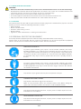
2.5 PERSONAL PROTECTIVE EQUIPMENT
Personal protective equipment protects sta from safety and health hazards while working.
Various tasks on and associated with, the system necessitate the use of personal protective equipment,
which is described in more detail in the individual sections of these instructions.
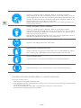
BREATHING APPARATUS
To protect against harmful gases, vapors, dust and similar materials and media.
Breathing apparatus (e.g. compressed air respirator) must be used when an oxy-
gen content of at least 17% in the ambient air is not guaranteed or when the limit of
a hazardous substance in the ambient air is exceeded more than 100-fold. Breath-
ing apparatus may only be worn by people who have been specially trained in
the use.
BREATHING APPARATUS, DEPENDENT ON AIR CIRCULATION
To protect against harmful gases, vapors, dust and similar materials and media.
Breathing apparatus must be worn if a permissible limit is exceeded 100-fold. The
breathing apparatus may only be used when the oxygen content in the ambient
air measures at least 17%.
PROTECTIVE GOGGLES
To protect the eyes against airborne parts and splashes of liquid.
CHEMICAL-RESISTANT GLOVES
To protect the hands from aggressive substances.
Make sure the protective gloves are leak-proof before wear, Before taking the
gloves o, clean them and then store them in a well ventilated location.
PROTECTIVE GLOVES
To protect the hands against abrasion, scrapes, pricks or deeper injuries and con-
tact with hot or cold surfaces.
WEAR HEARING PROTECTION
To protect the hands against abrasion, scrapes, pricks or deeper injuries and con-
tact with hot or cold surfaces.

10/48
EN
2.6 BEHAVIOR IN CASE OF FIRE OR ACCIDENT
Preventive Measure
• Always be prepared for fires and accidents!
• Always keep first aid equipment (kit, blankets, etc.) and fire extinguishing equipment in working order and
close to hand.
• Familiarize the sta with accident reporting, first aid and emergency procedures.
• Keep the access routes free for emergency service vehicles.
Measures in the event of fire or accident
• If there is no risk to your own safety, remove people from the danger zone.
• Administer first aid if necessary.
• Notify the fire brigade and/or emergency service.
• In the event of fire: If there is no risk to your own safety, use fire extinguishing equipment to fight the fire
until the fire brigade arrives.
• Inform the person responsible at the location.
• Make sure the access routes are free for emergency service vehicles.
• Direct the emergency service vehicles.
2.7 ENVIRONMENTAL PROTECTION
NOTE!
• Risk of environmental pollution from incorrect handling of environmentally hazardous substances!
• The environment can suer substantial damage if environmentally hazardous substances are handled,
and especially disposed of, incorrectly.
• Always observe the information below on handling environmentally hazardous substances and their dis-
posal.
• Take immediate measures if environmentally hazardous substances are accidentally released into the
environment. If in doubt, notify the responsible local authorities about the damage and enquire about the
suitable measures to be taken.
2.8 SIGNAGE
WARNING!
• Danger from illegible signs!
• Labels and signs can gather dirt or become otherwise illegible over time, thus preventing the recognition
of risks and compliance with the requisite operating information. This could result in injury.
• Make sure all safety, warning and operation information is legible at all times.
• Immediately replace any damaged signs or labels.
2.8.1 SIGNS THAT GIVE ORDERS
• No signs
2.8.2 SIGNS INDICATING BANS
• No signs
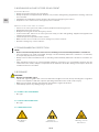
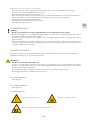
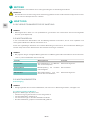
2.8.3 WARNING SIGNS
Gas Bottles
Hazard
Explosion -
Hazardous Area
Warning of Toxic
Substances

11/48
EN
TECHNICAL SPECIFICATIONS
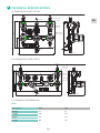
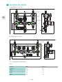
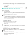
3.1 DIMENSION SHEET MTLM
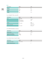
3.2 DIMENSION SHEET MTLS
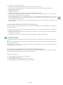
3.3 GENERAL INFORMATION
MTLM
Information Value Unit
Weight 5,5 kg
Length 250 mm
Depth 142 mm
Height 194 mm
3.
MTLM X XX XX XX XX XXXX XXXX X XXXX XXXX
*GAS TYPE:
S - STANDARD GASES
INLET PRESSURE:
F4 - 60 BAR
FX - 200 BAR
GX - 300 BAR
OUTLET PRESSURE:
D2 - 10 BAR
EZ - 20 BAR
E1 - 40 BAR
F2 - 100 BAR
INLET GAUGE TYPE:
BT - BOURDON TUBE
I1 - INDUCTIV CONTACT I1
R5 - REED CONTACT R5
OUTLET GAUGE TYPE:
BT - BOURDON TUBE
I2 - INDUCTIV CONTACT I2
R2 - REED CONTACT R2
I1 - INDUCTIV CONTACT I1
R5 - REED CONTACT R5
*RELIEF CONNECTION:
SEE THE LIST OF
CONNECTIONS
PROCESS INLET CONNECTION:
*PROCESS OUTLET CONNECTION:
SEE THE LIST OF CONNECTIONS
PURGING:
*PURGE CONNECTION:
*LIST OF CONNECTIONS
N14F - NPT1/4" FEMALE
M06B - COMPRESSION FITTING 6MM BRASS
M08B - COMPRESSION FITTING 8MM BRASS
M10B - COMPRESSION FITTING 10MM BRASS
M12B - COMPRESSION FITTING 12MM BRASS
M06S - COMPRESSION FITTING 6MM SS
M08S - COMPRESSION FITTING 8MM SS
M10S - COMPRESSION FITTING 10MM SS
M12S - COMPRESSION FITTING 12MM SS
IX4B - COMPRESSION FITTING 1/4" BRASS
IX6B - COMPRESSION FITTING 3/8" BRASS
IX8B - COMPRESSION FITTING 1/2" BRASS
IX4S - COMPRESSION FITTING 1/4" SS
IX6S - COMPRESSION FITTING 3/8" SS
IX8S - COMPRESSION FITTING 1/2" SS
*GAS TYPE
DEFINED BY PRODUCT LINE AND TYPE
(CHECK AVAILABLE GAS TYPE IN DATASHEET)
ORDERING INFORMATION
EXAMPLE: MTLMSGXE1I1BTN14FM06B1MO6BN14F
M14M - METRIC M14X1,5 M
N14F - NPT 1/4" F
W2ML - W21X1/14 M LH
W2MR - W21X1/14 M RH
0 - WITHOUT PURGING
1 - PURGE WITH PROCESS GAS
0000 - WITHOUT PURGING
SEE THE LIST OF
CONNECTIONS
Process
Outlet
Purge gas
Outlet
1
2
3
3
4
656
2
1
Purge gas
Outlet
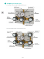
1 - GAS CYLINDER
2 - COIL
3 - INLET SHUT-OFF VALVE
4 - PRESSURE REGULATOR WITH IN/OUT GAUGE
5 - RELIEF VALVE
6 - PURGE OUTLET VALVE
250
194
70
30
2
approx. 142
25
8.5
10
140
8.5
135
Purge gas out
Purge gas out
Process Inlet
Process Inlet
Process Outlet
Purging line
Relief valve
Outlet
Position: Open
Positon: Open
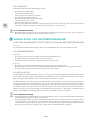
MTLS X XX XX XX XX XXXX XXXX X XXXX XXXX
*GAS TYPE:
S - STANDARD GASES
INLET PRESSURE:
F4 - 60 BAR
FX - 200 BAR
GX - 300 BAR
OUTLET PRESSURE:
D2 - 10 BAR
EZ - 20 BAR
E1 - 40 BAR
F2 - 100 BAR
INLET GAUGE TYPE:
BT - BOURDON TUBE
I1 - INDUCTIV CONTACT I1
R5 - REED CONTACT R5
OUTLET GAUGE TYPE:
BT - BOURDON TUBE
I2 - INDUCTIV CONTACT I2
R2 - REED CONTACT R2
I1 - INDUCTIV CONTACT I1
R5 - REED CONTACT R5
*RELIEF CONNECTION:
SEE THE LIST OF
CONNECTIONS
PROCESS INLET CONNECTION:
*PROCESS OUTLET CONNECTION:
SEE THE LIST OF CONNECTIONS
PURGING:
*PURGE CONNECTION:
*LIST OF CONNECTIONS
N14F - NPT1/4" FEMALE
M06B - COMPRESSION FITTING 6MM BRASS
M08B - COMPRESSION FITTING 8MM BRASS
M10B - COMPRESSION FITTING 10MM BRASS
M12B - COMPRESSION FITTING 12MM BRASS
M06S - COMPRESSION FITTING 6MM SS
M08S - COMPRESSION FITTING 8MM SS
M10S - COMPRESSION FITTING 10MM SS
M12S - COMPRESSION FITTING 12MM SS
IX4B - COMPRESSION FITTING 1/4" BRASS
IX6B - COMPRESSION FITTING 3/8" BRASS
IX8B - COMPRESSION FITTING 1/2" BRASS
IX4S - COMPRESSION FITTING 1/4" SS
IX6S - COMPRESSION FITTING 3/8" SS
IX8S - COMPRESSION FITTING 1/2" SS
*GAS TYPE
DEFINED BY PRODUCT LINE AND TYPE
(CHECK AVAILABLE GAS TYPE IN DATASHEET)
ORDERING INFORMATION
EXAMPLE: MTLSSGXEZI1BTN14FM06B1MO6BN14F
M14M - METRIC M14X1,5 M
N14F - NPT 1/4" F
W2ML - W21X1/14 M LH
W2MR - W21X1/14 M RH
0 - WITHOUT PURGING
1 - PURGE WITH PROCESS GAS
0000 - WITHOUT PURGING
SEE THE LIST OF
CONNECTIONS
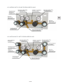
1 - GAS CYLINDER
2 - COIL
3 - INLET SHUT-OFF VALVE
4 - PRESSURE REGULATOR WITH IN/OUT GAUGE
5 - FIXED PRESSURE REGULATOR WITH IN GAUGE
6 - RELIEF VALVE
7 - PURGE OUTLET VALVE
FIX
1 1
22
3 3
4
6
7 7
5
Purge gas
outlet
Purge gas
outlet
Process
outlet
Purge gas out
Purge gas out
Process Inlet
Process Inlet
Process Outlet
194
70
400
2
30
approx. 145
Purging line
10
8.5
140
8.5
25
135
Relief valve
Outlet
Positon: Open
Position: Open

12/48
EN
MTLS
Information Value Unit
Weight 6,8 kg
Length 400 mm
Depth 145 mm
Height 194 mm
3.4 CONNECTION VALUES
Information Value Unit
Inlet M14x1,5M
1/4“
W21x1/14M LH
W21x1/14M RH
metric
NPT
Outlet ¼“
6, 8, 10, 12
NPT
fitting mm
Outlet relief valve ¼“
6, 8, 10, 12
NPT female
fitting mm
3.5 PERFORMANCE VALUE
Information Value Unit
Nominal flow 20 m3/h
Inlet pressure (max.) 300 bar
Outlet pressure (max.) 10-100 bar
3.6 OPERATING CONDITIONS
Information Value Unit
Temperature range -20 till +60 °C
Relative humidity (max.) 98 %

13/48
EN
SETUP AND FUNCTION
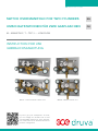
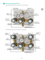
4.1 OVERVIEW MTLM WITHOUT INERT GAS PURGING
4.2 OVERVIEW MTLM WITH INERT GAS PURGING
4.

14/48
EN
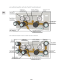
4.3 OVERVIEW MTLS WITHOUT INERT GAS PURGING
4.4 OVERVIEW MTLS WITH INERT GAS PURGING

15/48
EN
4.5 BRIEF DESCRIPTION MTLM MANUAL SWITCH OVER
With the switch over manifold type MTLM an industrial, non-toxic and non-corrosive gas or gas mixture, which
is stored inside gas cylinder or bundle with over pressure. This over pressure is reduced from maximum 300
bar to tubing pressure (10 bar, 20 bar, 40 bar, 100 bar).
The user can change manually between two high pressure sources with two high pressure valves.
A relief valve at pressure regulator secures the manifold with its outlet pressure against incorrect pressure
rising at the outlet due to leakage in regulator seat.
The real inlet and outlet pressure of the manifold is displayed at the pressure gauges. There is the possibility
to use contact gauges for inlet and outlet pressure. If the manifold has the opportunity for inert gas purging,
this can be done before initial start-up to remove contaminates. Furthermore it is possible to depressurize the
high pressure side before cylinder is changed.
The described system is mounted on a stainless steel plate. Due to plate dimensions all components are
protected against damage inside of package, during transport and in mounted condition. The split design of
plate enables to mount the component easy and with less weight.
The hole in the front plate enables to change the gauge without disassembly of the complete manifold. At the
ground plate at both sides are holes to connect the cylinder hoses with carabiner hook. To connect ground-
ing you can find screw at the ground plate.
The development, construction and production testing is according to the following standards:
• regulators- ISO 7291
• valves- ISO 10297
• gauges EN 837-1
• mechanical explosion prevention of complete manifold- ISO80079-36; IEC 60079-32-1; TRGS 727
4.6 BRIEF DESCRIPTION MTLS SEMI AUTOMATIC SWITCH OVER
With the switch over manifold type MTLS an industrial, non-toxic and non-corrosive gas or gas mixture, which
is stored inside gas cylinder or bundle with over pressure. This over pressure is reduced from maximum 300
bar to tubing pressure (10 bar, 20 bar, 40 bar, 100 bar).
This manifold takes the outlet pressure dierence between two regulators to switch over between two high
pressure inlets. The user can define in which direction the switch over works.
A relief valve at pressure regulator secures the manifold with its outlet pressure against incorrect pressure
rising at the outlet due to leakage in regulator seat.
The real inlet and outlet pressure of the manifold is displayed at the pressure gauges. There is the possibility
to use contact gauges for inlet and outlet pressure. If the manifold has the opportunity for inert gas purging,
this can be done before initial start-up to remove contaminates. Furthermore it is possible to depressurize the
high pressure side before cylinder is changed.
The described system is mounted on a stainless steel plate. Due to plate dimensions all components are
protected against damage inside of package, during transport and in mounted condition. The split design of
plate enables to mount the component easy and with less weight.
The hole in the front plate enables to change the gauge without disassembly of the complete manifold. At the
ground plate at both sides are holes to connect the cylinder hoses with carabiner hook. To connect ground-
ing you can find screw at the ground plate.
The development, construction and production testing is according to the following standards:
• regulators- ISO 7291
• valves- ISO 10297
• gauges EN 837-1
• mechanical explosion prevention of complete manifold- ISO80079-36; IEC 60079-32-1; TRGS 727

16/48
EN
TRANSPORT, PACKAGING AND STORAGE
TIPS AND RECOMMENDATIONS!
• The installation and start- up of this gas supply panel is normally done by the supplier or by authorized
personnel.
• Even though there can be some users or maintenance personnel who care about the packaging. The fol-
lowing notes should be observed accordingly.
5.1 SAFETY INFORMATION FOR TRANSPORTATION
NOTE!
• Damages caused by inappropriate transportation!
• If transported inappropriately, consignments can fall or topple over. This can cause considerable property
damage.
• When unloading the consignments on delivery and transporting them on the premises, act with caution
and observe the symbols and warnings on the packaging.
• Use only the attachment points provided.
• Do not remove the packaging until you are ready to assemble the regulator.
5.2 TRANSPORT INSPECTION
Upon delivery, check immediately that the consignment is complete and has not been damaged during tran-
sit. Procedure on detection of visible transport damage:
• Refuse acceptance of the delivery or only accept subject to reservation
• Record the extent of the damage on the transportation documentation or on the forwarder’s delivery note
• File a complaint
TIPS AND RECOMMENDATIONS!
• Report each and every defect as soon as you discover it. Claims for damages can only be asserted within
the specified periods.
5.3 PACKAGING
The individual consignments are packed according to the anticipated transport conditions. Without exception
all packaging is made of environmentally friendly material.
The packaging is intended to protect the individual components against transport damage, corrosion and
other damage until they are ready for installation. Do not, therefore, destroy the packaging; only remove it
when assembly is imminent.
NOTE!
• Risk of environmental harm through incorrect disposal!
• Packaging materials are valuable raw materials. In many cases they can be re-used or recycled. Incorrect
disposal of packaging materials can harm the environment.
• Dispose of packaging materials in an environmentally compatible manner.
• Observe locally applicable disposal regulations. If necessary, commission a specialist disposal firm.
5.4 STORAGE
Store the packages in the following conditions:
• Do not store outdoors
• Store in a dry and dust-free location
• Do not expose to aggressive media
• Protect from sunlight radiation
• Avoid mechanical jolts
• Storage temperature: 15 to 35 °C
• Relative humidity: max. 60 %
• If storing for longer than 3 months, regularly inspect the general condition of all parts and the packaging.
If necessary re-apply or renew the rust-proofing
5.

17/48
EN
TIPS AND RECOMMENDATIONS!
• Some packages may bear labels with storage information that extends beyond these requirements. These
notes should be observed accordingly.
INSTALLATION AND INITIAL STARTUP
6.1 SAFETY NOTES FOR INSTALLATION AND INITIAL STARTUP
Sta
Installation and initial start-up of the system may only be performed by qualified sta.
6.2 PREPARATION
Unpacking
• The system components should be removed from their packaging carefully and prudently.
• Additional protective packaging should also be removed.
• Check all components of damages from transport
Depressurize
• Depressurize components and purge with inert gas if necessary
• Cut tubing with special tool; avoid contaminations (dirt, cuttings, etc.)
• Check perfect condition of components and purity of connections
6.3 INSTALLATION
The back plate of the manifold is mounted at the above mentioned height. The front plate is suspend in the
back plate and secured with the delivered screw below in the middle.
The manifold is mounted with compression fittings at process inlet, process outlet, relief valve and purge out-
let (if existent). First remove the plastic caps from all connections. The piping has to be inserted completely
into the compression fitting. Than screw the nut hand tight. After that screw with a jaw spanner 1 ¼ turns tight.
Connect the relief tubing the same way. It is not allowed to connect relief and purge tubing. They had to go
separately and safe to the outside.
TIPS AND RECOMMENDATIONS!
• To connect the gas cylinder to the manifold coils and flexible hoses are suitable (available accessories)
• The stainless steel coils or flexible hose is always delivered separately. The correct allocation has to be
proved. At the connection nut you can see the type of cylinder connection. There is only one design of
coil/ hoses to connect it at the right and left side of manifold.
• To mount the coil/ hose please remove plastic caps from the thread. Make sure that the gasket, which
is scope of delivery, is inserted. Connect the nut with the inlet of the manifold hand tight and afterwards
screw with a jaw spanner.
• To connect the coil/hose with the gas cylinder, the thread of the cylinder valve and of the nut need to be in
perfect condition. Any time you connect new gas cylinder, use new cylinder connection.
• Only coils and hoses from manufacturer suitable for used gases have to be used. Check gasket or correct
position in connection thread of coil/hose. Using a spanner extension is not allowed, it can cause damage
of thread and gasket and leads to leakage.
6.4 REQUIRED QUALIFICATIONS FOR INITIAL STARTUP AND CYLINDER
CHANGING
• The test protocols from the piping according to tightness and if necessary moisture and particles are
available
• Process gas tubing, vent piping and purge gas tubing is connected
• In process gas tubing is only standard gas ( see 1.2)
• The start-up is only realized by qualified personal
• Wear safety clothes according to regulations
• Use spark-free tools and provide before installation
• Before first start-up check type label, if the switch over manifold is suitable for the provided purpose (gas,
pressure, material, etc.)
6.

18/48
EN
6.5 INITIAL START UP
• All requirements are fulfilled as on point 6.4
• Pressure regulator is depressurized, handwheel turned completely to left side
WARNING!
• Make sure the panel components are not exposed to pressure levels that exceed their respective permis-
sible nominal pressure.
• Make sure that nobody could be hurt because of the initial start-up of manifolds.
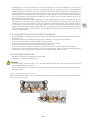
MTLS – basic setting ex works
Both pressure regulators were set to identical outlet pressure. The arrow on the left pressure regulator points
downwards.
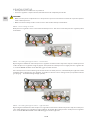
MTLS – Presetting through customer – left side first
By turning the handwheel of the left pressure regulator clockwise all the way to the stop, the outlet pressure
of the left pressure regulator is higher (approx. 2 bar) than the outlet pressure of right pressure regulator. As
a result the MTLM manifold starts with taking gas from the left side.
If the inlet pressure on the left side gets lower than the set outlet pressure, automatically the right side of the
manifold starts to provide the gas. Cylinder or bundle on left side can be changed now (see points 6.5.1 Inert
gas purging … and 6.5.3 Change empty cylinder).
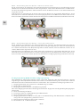
MTLS – Presetting through customer – right side first
By turning the handwheel of the left pressure regulator anti clockwise all the way to the stop, the outlet pres-
sure of the right pressure regulator is higher (approx. 2 bar) than the outlet pressure of left pressure regulator.
As a result the MTLM manifold starts with taking gas from the right side.

19/48
EN
If the inlet pressure on the right side gets lower than the left regulator outlet pressure, automatically the left
side of the manifold starts to provide the gas. Cylinder or bundle on right side can be changed now (see point
6.5.1 Inert gas purging and 6.5.3 Change empty cylinder).
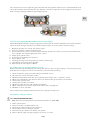
6.5.1 Inert gas purging (MTLM and MTLS with inert gas purging)
Switch Over Manifolds with inert gas purging were used to get air from the atmosphere out of the manifold,
when you have changed cylinder or you want to depressurize coil or hose before cylinder change.
1. Outlet purge valves are closed, red mark is visible
2. Pressure regulator is depressurized (closed)
3. Close inlet pressure valves, red mark visible. Now the inlet pressure valve is just closed in direction pres-
sure regulator. The way through purge valve is open.
4. Slowly open cylinder valve
5. Processgas is streaming into coil/ hose
6. Close cylinder valve
7. Shortly open purge valve and let the gas from the coil/hose go
8. Immediately close purge valve after that
9. Repeat steps 4.-8. For approx., 10 time
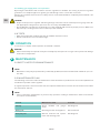
6.5.2 Fill the process gas tubing with process gas
Before initial start-up and filling the gas tubing with process gas inert gas purging is necessary (see point
6.5.1). Because of safety reasons we recommend to connect relief gas tubing.
1. Check if coil/hose, purge and relief tubing are installed correct.
2. All valves are closed, red mark is visible
3. MTLM: turn handwheel of the pressure regulator all the way to stop – regulator is closed
4. MTLS: turn handwheel in the direction where you want to take gas from first (see point 6.5)
5. Slowly open cylinder valve
6. Slowly open inlet pressure valves.
7. MTLM: set outlet pressure with regulator handwheel
8. MTLS: outlet pressure is fixed, arrow shows which side is working first
9. Manifold is now in operation
We recommend checking the manifold and pressure gauges on daily basis.
6.5.3 Change empty gas cylinder
TIPS AND RECOMMENDATIONS!
• MAK- Value (see Technical Rules for Hazardous Substances, TRGS 900)
1. Close cylinder valve
2. Close inlet valve on empty cylinder side
3. Open purge valve to depressurize coil/ hose.
4. Disassemble coil/ hose from gas cylinder
5. Connect new gas cylinder, use always new gasket
6. Before start-up again inert gas purging is necessary, see 6.5.1

20/48
EN
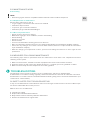
6.5.4 Taking gas supply panel out of operation
By turning the handwheel anti clockwise close the regulator on manifold. The closing of pressure regulator
guarantees no complete tight ness against gas leak through coils or connected consumers.
Always close cylinder valve because of safety reasons. If the manifold will be completely disassembled, note
the following:
DANGER!
• Depressurize pressure regulator and tubing through consumer. Inlet and outlet pressure gauge show “0”
bar. Appropriate safeguards for personnel are necessary. Note MAK-Values.
• Unconditionally note that it is not allowed to use the manifold with more than proper pressure. Make sure
that nobody is endangered because of start-up of the manifold.
6.6 TESTS
• After pressurizing the complete function of manifold should be tested.
• Check relief valve, it has to be bubble tight
OPERATION
In reference to chapter 2.1 the operation of manifold is defined.
BEWARE!
• Valves must always be opened slowly and carefully to prevent pressure surges in the system and damage
to the other components!
MAINTENANCE
8.1 SAFETY NOTES FOR MAINTENANCE
NOTE!
• Maintenance may only be performed by suciently qualified, trained and authorized individuals (see sec-
tion 2.4)
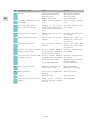
8.2 MAINTENANCE PLAN
The following sections describe the maintenance works that must be performed to ensure the optimum and
trouble-free operation of the regulator.
If regular inspections reveal increased wear, the requisite maintenance intervals must be shortened to reflect
the actual wear and tear.
NOTE!
• Please contact the manufacturer if you have any questions relating to maintenance works and intervals
(see 1.8 for contact details).
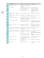
Interval Maintenance work Personal
Weekly Check manifold and gauges
visual
Gas-Engineer
Every year Checking function and tightness Gas-Technician
Every 10 years General overhaul and replace-
ment of all wearing parts.
Gas-Engineer
7.
8.
Seite wird geladen ...
Seite wird geladen ...
Seite wird geladen ...
Seite wird geladen ...
Seite wird geladen ...
Seite wird geladen ...
Seite wird geladen ...
Seite wird geladen ...
Seite wird geladen ...
Seite wird geladen ...
Seite wird geladen ...
Seite wird geladen ...
Seite wird geladen ...
Seite wird geladen ...
Seite wird geladen ...
Seite wird geladen ...
Seite wird geladen ...
Seite wird geladen ...
Seite wird geladen ...
Seite wird geladen ...
Seite wird geladen ...
Seite wird geladen ...
Seite wird geladen ...
Seite wird geladen ...
Seite wird geladen ...
Seite wird geladen ...
Seite wird geladen ...
Seite wird geladen ...
-
 1
1
-
 2
2
-
 3
3
-
 4
4
-
 5
5
-
 6
6
-
 7
7
-
 8
8
-
 9
9
-
 10
10
-
 11
11
-
 12
12
-
 13
13
-
 14
14
-
 15
15
-
 16
16
-
 17
17
-
 18
18
-
 19
19
-
 20
20
-
 21
21
-
 22
22
-
 23
23
-
 24
24
-
 25
25
-
 26
26
-
 27
27
-
 28
28
-
 29
29
-
 30
30
-
 31
31
-
 32
32
-
 33
33
-
 34
34
-
 35
35
-
 36
36
-
 37
37
-
 38
38
-
 39
39
-
 40
40
-
 41
41
-
 42
42
-
 43
43
-
 44
44
-
 45
45
-
 46
46
-
 47
47
-
 48
48


GCE SWITCH OVER MANIFOLD Bedienungsanleitung
- Typ
- Bedienungsanleitung
in anderen Sprachen
Verwandte Artikel
-
GCE -PTALX Bedienungsanleitung
-
GCE Manifold Bedienungsanleitung
-
-
-
-
-
-
-
-