Zenner capsule meter Minomess BR (HT2) Installationsanleitung
- Typ
- Installationsanleitung

1
Messkapselzähler Minomess BR (HT2)
Deutsch
Montageanleitung
Abb. 1
Abb. 2
Abb. 3
Abb. 4
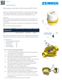
Minomess Austausch-Messkapselzähler zur adapterfreien Montage in
vorhandene Wasserzähler - Anschlussstücke (Unterputzteile). Ausfüh-
rung als Warm- oder Kaltwasserzähler mit Magnetabschirmung.
Hinweise
Die Montage muss durch geschultes Fachpersonal durchgeführt wer-
den. Es sind ausschließlich die Originaldichtungen des Herstellers zu
verwenden.
Das bauseits vorhandene Anschlussstück ist zweifelsfrei zu identizie-
ren.
Nur für vertikalen Einbau zugelassen.
Typ der Anschluss-
schnittstelle nach
DIN EN ISO 4064
Original-Hersteller Bezeichnung Gewinde
HT2 Brunata-Metrona 307/1, HT2 M66x1
Der Einbau eines falschen Zählers kann zu Leckagen oder/und Beschä-
digungen der Gewinde von Unterputzteil und Messkapselzähler führen.
1. Lieferumfang
■Minomess Messkapselzähler
■Einlaufbuchse [1]
■O-Ring 60x2 [2]
■Formdichtung [3]
■Sicherungsring [4]
2. Erstmontage des Messkapselzählers
2.1. Leitung sorgfältig durchspülen.
2.2. Leitung durch Zudrehen des Wohnungs- oder Strangabsperr-
ventils absperren und entleeren.
2.3. Montageschutzhaube entfernen.
2.4. Mit einem Montageschlüssel den Deckel des Unterputzteils
(UPT) önen. Deckel und Dichtring entnehmen.
2.5. Messkapselzähler aus der Verpackung nehmen, auf Unversehrt-
heit und Vollständigkeit prüfen (siehe Lieferumfang).
2.6. Überprüfen, dass die Messkapsel in ihre vorgesehene An-
schlussschnittstelle hineinpasst: Kennzeichnung auf dem
Typenschild: HT2 (siehe Abb. 2 und Hinweise).
2.7. Dichtächen im UPT sorgfältig reinigen.
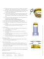
2.8. Neue Einlaufbuchse [1] vollständig in die Önung des Ein-
laufkanals des UPT stecken (Abb. 3). Pfeil für die Angabe der
Strömungsrichtung im Boden des UPT beachten.
2.9. Überprüfen, ob der mit der Messkapsel mitgelieferte O-Ring
60x2 [2] richtig sitzt. Falls dies nicht der Fall ist, muss der
O-Ring [2] in die vorgesehene Nut am Zählereinsatz eingelegt
werden (Abb. 4).
2.10. O-Ring [2] und die Formdichtung [3] einfetten.
⇑⇑
[1]
[1]
[2]

2
Technische Änderungen vorbehalten. Für etwaige Irrtümer und Druckfehler übernehmen wir keine Haung. ZRI_SAP166540_220601_DE_EN
ZENNER International GmbH & Co. KG
Heinrich-Barth-Straße 29 | 66115 Saarbrücken | Germany
Telefon +49 681 99 676-30
Telefax +49 681 99 676-3100
E-Mail info@zenner.com
Internet www.zenner.com
Abb. 5
2.11. Prüfen, dass die neue Formdichtung [3] korrekt in der vorgese-
henen Nut an der Auslaufseite sitzt (Abb. 5). Ggf. korrigieren.
2.12. Mit dem Montageschlüssel die Messkapsel ins UPT führen (Abb.
6). Dabei auf Durchussrichtung gemäß Pfeile im UPT und
unter der Messkapsel achten.
2.13. Unter leichtem Andruck durch kurzes Drehen im Gegenuhrzei-
gersinn den Gewindeanfang nden und dann die Messkapsel
im Uhrzeigersinn festschrauben. Das Zählwerk dreht sich dabei
mit.
2.14. Leitung durch Önen des Wohnungs- oder Strangabsperrven-
tils vorsichtig unter Druck setzen.
Dichtheit und Funktion sorgfältig überprüfen.
2.15. Zähler mit dem Sicherungsring [4] plombieren (Abb. 7).
2.16. Anschlussschnittstelle mit Aufkleber HT2 kennzeichnen.
2.17. Sofern noch nicht geschehen, das Zählwerk in Ableseposition
drehen.
2.18. Rosette und sofern durch große Einbautiefe erforderlich, eine
bis drei Verlängerungshülsen aufstecken (Abb. 7).
3. Zählertausch
3.1. Leitung durch Zudrehen des Wohnungs- oder Strangabsperr-
ventils absperren und entleeren.
3.2. Rosette abziehen.
3.3. Mit dem Montageschlüssel den Messeinsatz aus dem UPT
schrauben.
3.4. Vorhandenes Sieb oder Führungsstück aus der Einlaufönung
des UPT entfernen.
3.5. Den neuen Messeinsatz, wie unter Zi. 2.5 bis 2.18 beschrieben,
montieren. Dichtheit und Funktion sorgfältig prüfen.
4. Montageschlüssel
Zur Montage und Demontage der Messkapselzähler Minomess BR
dient ein universal Montageschlüssel.
5. Benutzersicherung
Es muss eine Benutzersicherung (Klebemarke, Verplombung o. ä.)
verwendet werden, um zu erkennen, ob die Messkapsel aus der An-
schlussschnittstelle ausgebaut worden ist, bzw. um einen unerlaub-
ten Ausbau zu verhindern.
Die Konformitätserklärung ist im Lieferumfang enthalten. Diese, und die
neuesten Informationen zum Produkt können auch unter www.zenner.
de abgerufen werden.
[3]
[4]
Abb. 6
Abb. 7

3
Capsule meter Minomess BR (HT2)
English
Installation manual
Fig. 1
Fig. 2
Fig. 3
Fig. 4
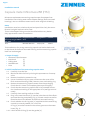
Minomess replacement measuring capsule meter for adapter-free
installation into existing water meter adapter ttings (ush-mounted
housings). Hot or cold water meter version with magnetic shielding.
Notes
Installation must be carried out by trained specialists. Only the manu-
facturer’s original seals are to be used.
The on-site adapter tting must be identied without any doubt.
Only approved for vertical installation.
Type of connection inter-
face according to DIN EN
ISO 4064
Original-Manufac-
turer
Designation Thread
HT2 Brunata-Metrona 307/1, HT2 M66x1
The installation of a wrong measuring capsule can lead to leaks and/
or the thread of the ush-mounted housing and the measuring capsule
itself can be damaged.
1. Scope of supply
■Minomess capsule meter
■Inlet-bush [1]
■O-Ring 60x2 [2]
■Moulded seal [3]
■Fuse [4]
2. Initial installation of the measuring capsule meter
2.1. Carefully rinse the line.
2.2. Block and drain the line by closing the apartment or line stop
valve.
2.3. Remove installation protection cap.
2.4. Use an installation key to open and remove the cover of the
ush-mounted housing (FMH). Remove cover and sealing ring
2.5. Remove the measuring capsule meter from the packaging.
Check that it is intact and complete (see scope of supply).
2.6. Check that the measuring capsule ts in its intended connec-
tion interface: Marking on the type plate: HT2 (see gure 2 and
notes).
2.7. Carefully clean sealing surfaces in FMH.
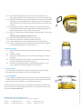
2.8. Plug in the new inlet-bush [1] into the inlet channel of the ush-
mounted housing completely (Fig. 3). Please note the arrow for
ow direction at the bottom of the ush-mounted housing.
2.9. Check whether the O-ring 60x2 [2] supplied with the measuring
capsule is correctly seated. If it is not, the
O-ring [2] must be inserted in the correct groove on the meter
insert (Fig. 4).
2.10. Lubricate the O-Ring [2] and the gasket [3].
⇑⇑
[1]
[1]
[2]

4
Subject to technical modications. We accept no liability for any errors or misprints. -
Fig. 5
2.11. Check that the moulded seal [3] is correctly seated in the
groove provided on the outlet side (Fig. 5). Correct if necessary
2.12. Use the installation key to guide the measuring capsule into the
FHM (Fig. 6). Pay attention to the ow direction in accordance
with the arrow on the FMT and on the bottom of the measuring
capsule.
2.13. Using slight pressure briey turning anti-clockwise, nd the
start of the thread and then tighten the measuring capsule in a
clockwise direction. The counter also rotates.
2.14. Set line under pressure by opening the apartment or main stop
valve.
Carefully check tightness and function.
2.15. Seal the meter with the safety-ring [4] (Fig. 7).
2.16. Mark the connection interface with sticker HT2.
2.17. If not already done, turn the register to the read position.
2.18. Insert rosette and if required due to the large insertion depth,
one to three extension connectors (Fig. 7).
3. Meter exchange
3.1. Block and drain the line by closing the apartment or line stop
valve.
3.2. Remove rosette.
3.3. Using the assembly key, unscrew the measuring insert from
the FMH.
3.4. Remove (if present) old strainer or inlet-bush from the inlet
channel of the ush-mounted housing.
3.5. Install new measuring insert, as described under No. 2.5 to
2.18. Carefully check leak tightness and function.
4. Assembly key
For installation and dismantling of the measuring Capsule meter
Minomess BR can be used a universal Assembly key.
5. User safeguard
A user safeguard (adhesive label, seal etc.) must be used to identify
whether the measuring capsule has been removed from the connec-
tion interface or to prevent an unauthorised removal.
The declaration of conformity is included in the delivery. The declara-
tion of conformity and the latest information on this product can also
be found at www.zenner.de.
[3]
[4]
Fig. 6
Fig. 7
ZENNER International GmbH & Co. KG
Heinrich-Barth-Straße 29 | 66115 Saarbrücken | Germany
Telefon +49 681 99 676-30
Telefax +49 681 99 676-3100
E-Mail info@zenner.com
Internet www.zenner.de
-
 1
1
-
 2
2
-
 3
3
-
 4
4


Zenner capsule meter Minomess BR (HT2) Installationsanleitung
- Typ
- Installationsanleitung
in anderen Sprachen
Verwandte Artikel
-
Zenner Minomet measuring capsule meter Bedienungsanleitung
-
-
-
-
-
-
-
-
-