Thermo Fisher Scientific Dionex UltiMate 3000 Series Bedienungsanleitung
- Typ
- Bedienungsanleitung

Revision 1.8 October 2013 © Thermo Fisher Scientific Inc.
Doc. No. 4801.0025 All rights reserved
All trademarks are property of Thermo Fisher Scientific Inc. and its subsidiaries.
Packing Instructions
for the Devices of the
Thermo Scientific Dionex
UltiMate 3000 Series
For instructions in English, see page 1.
Verpackungsvorschrift
für die Geräte der
Thermo Scientific Dionex
UltiMate 3000-Serie
Die deutsche Anleitung finden Sie ab Seite 22.

Seite 1 Page 1
To prevent the devices of the Thermo Scientific Dionex™ UltiMate™ 3000 series from being
damaged during transit when they need to be returned to the factory, always use the original
shipping container and observe the packing instructions in this document. We would also like
to point out that inappropriate packaging automatically voids the product warranty. If the
original packaging is no longer available, appropriate shipping containers and packing
material can be ordered from the Thermo Fisher Scientific sales organization for Dionex
HPLC products.
Follow the steps for the device that you want to ship:
1 Autosamplers ................................................................................................................. 2
2 Flow Managers and Thermostatted Column Compartments ................................... 3
3 Pumps ............................................................................................................................. 4
4 Detectors ......................................................................................................................... 4
5 Nano/Cap System .......................................................................................................... 7
6 Nano/Cap Pump ............................................................................................................ 9
7 Packing UltiMate 3000 Devices .................................................................................. 10
7.1 Packaging with Foam Inserts ............................................................................... 11
7.2 Packaging with Foam Braces ............................................................................... 12
8 Solvent Racks ............................................................................................................... 15
9 Automated Fraction Collector ................................................................................... 16
10 XRS Open Autosamplers ............................................................................................ 17
Die deutsche Anleitung finden Sie ab Seite 22.

Seite 2 Page 2
1 Autosamplers
WPS-3000 (all models) and ACC-3000
For packing instructions for the OAS-3x00 Open Autosamplers refer to page 17.
1. Shut down the autosampler as described in the Operating Instructions.
This is a must! Verify that
♦ All movable parts of the carousel (vial trays (racks), vials and well plates, and the 5-
position vial holders for the 10-mL vials* if applicable) and also the wash liquid reservoir
if installed have been removed. If you have to return these parts, ship them in the
accessories box. Make sure that no vials are present in the trays.
* For autosamplers with serial number 8013423 and higher, the 5-position holder may
remain in the autosampler.
♦ The needle and needle arm are in the appropriate position for shipment (that is the needle
arm is on the right and the needle is out of the needle seat and wash port). If they are not,
move them into the correct position by either pressing the Standby button on the front of
the autosampler or performing the Standby command from ChromeleonTM.
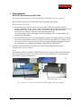
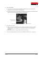
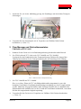
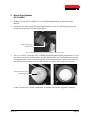
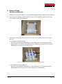
2. Push the foam insert that secures the needle arm during transit into the sample
compartment as far as it goes in.
Note:
Autosamplers with serial number 8010458 and higher are shipped with a black foam insert
that secures also the carousel cover. Move the cover to the left before you push the foam
insert into the sample compartment.
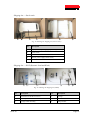
Fig. 1: Foam insert securing the needle arm (left: WPS-3000PL; right: WPS-3000RS)
Foam insert securing
the needle arm
Foam insert securing the needle
arm and carousel cover

Seite 3 Page 3
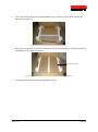
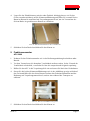
3. Tilt the front panel upward and secure the panel as shown in the picture by using the two
foam inserts.
Fig. 2: Foam insert for the front panel (here in a WPS-3000PL)
4. To proceed continue with the steps in Packing UltiMate 3000 Devices (→ page 10).
2 Flow Managers and Thermostatted Column Compartments
FLM-3x00 and TCC-3x00
1. Shut down the device as described in the Operating Instructions.
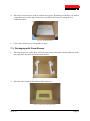
2. Only FLM-3x00 and TCC-3x00 (not TCC-3000SD and TCC-3000RS)
Secure the front panel door. To do so, press the release button for the door and push the
foam insert into the opening as far as it goes in.
Fig. 3: Securing the front panel door
3. Only TCC-3000SD and TCC-3000RS
This is a must! If the TCC is fitted with one or two column switching valves, you have to
remove the entire valve unit (drive and drip tray) before you place the TCC in the shipping
container. You may reinstall the long side panel that was installed when the TCC was
shipped. If a valve unit needs to be returned, use the packaging in which the valve unit was
shipped.
4. To proceed continue with the steps in Packing UltiMate 3000 Devices (→ page 10).
Foam insert securing the front panel
Insert to secure the front panel door

Seite 4 Page 4
3 Pumps
All pumps of the UltiMate 3000 Pump Series
1. Shut down the pump as described in the Operating Instructions.
2. Tilt the front panel door upward and secure the door as shown in the picture by using the
two foam inserts.
Fig. 4: Securing the pump door (here insert installed on the left)
3. To proceed continue with the steps in Packing UltiMate 3000 Devices (→ page 10).
4 Detectors
VWD-3x00, DAD-3000, MWD-3000, FLD-3x00, PDA-3000, UVD-3000,
ECD-3000RS, Corona Veo (RS) (all models)
1. Shut down the detector as described in the Operating Instructions.
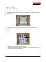
2. Only VWD-3x00, DAD-3000, and MWD-3000 (all models)
♦ Verify that a flow cell (or dummy cell) is installed. This is to prevent that dust particles
cause damage to the detector optics.
♦ Secure the optics for shipment:
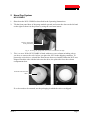
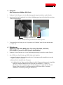
a) Push the cardboard with the information about the shipping locks under the orange
shipping locks on the detector bottom as shown in the picture (→ page 5).
(The cardboard was installed when the detector was shipped and is included in the
shipping container for detectors, which can be ordered from the Thermo Fisher
Scientific sales organization for Dionex HPLC products.)
Insert to secure the front panel door
(depending on the pump type)

Seite 5 Page 5
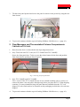
b) Tighten the shipping locks.
c) Wrap the cardboard around the front panel door.
d) Use tape to secure the cardboard to the detector top.
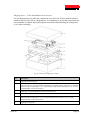
Fig. 5: Securing the detector optics (left: VWD-3x00; right: DAD/MWD-3x00)
Fig. 6: Cardboard with notice at detector front
3. Only FLD-3x00
Ship the FLD without a flow cell being installed. Instead, reinstall the flow cell cover that
was installed when the detector was shipped.
Close the flow cell inlet and outlet with the plugs with which the flow cell was shipped. If a
flow cell needs to be returned, use the packaging in which the flow cell was shipped.
Shipping locks
Shipping locks
Cardboard

Seite 6 Page 6
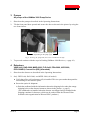
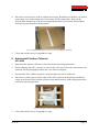
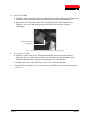
4. Only ECD-3000RS
♦ Verify that no cell and potentiostat module is installed. This is to prevent that they
damage the detector electronics during shipment.
♦ Tilt the front panel door of the detector upward and secure the door on the left and on the
right as shown in the picture by using the two foam inserts.
Fig. 7: Securing the detector door (here insert installed on the left)
5. Only Corona Veo (RS)
♦ Make sure that you reinstall the protective tubing on the nebulizer that was installed
when the nebulizer was shipped. Store and ship the nebulizer in its original foam
packaging.
♦ Reinstall the white cover on the right front side of the detector.
6. To proceed continue with the steps in Packing UltiMate 3000 Devices (→ page 10).
Insert to secure the
front panel door

Seite 7 Page 7
5 Nano/Cap System
NCS-3500RS
1. Shut down the NCS-3500RS as described in the Operating Instructions.
2. Tilt the front panel door of the pump module upward and secure the door on the left and
on the right as shown in the picture by using the two foam inserts.
Fig. 8: Securing the pump door (here insert installed on the left)
3. This is a must! If the NCS-3500RS is fitted with one or two column switching valves,
you have to remove the valve before you place the NCS in the shipping container. To
protect the valve drives, reinstall the foam inserts that were installed when the NCS was
shipped. Push the side with the hole onto the drive; the plain side faces the column
compartment door.
Fig. 9: Protecting the valve drive
If a valve needs to be returned, use the packaging in which the valve was shipped.
Insert to secure the
front panel door
Push this side onto the
drive.

Seite 8 Page 8
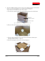
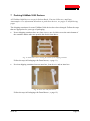
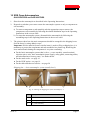
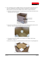
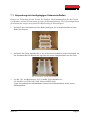
4. The NCS-3500RS packaging consists of a three-piece shipping container (with container
bottom, spacer box, and container cover) and the actual packaging box.
Always ship the NCS-3500RS on a pallet. This is a must!
a) First, place the container bottom on the pallet and place the spacer box in the bottom.
Fig. 10: Shipping container with bottom and spacer box
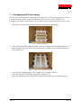
b) Place one of the foam corners in each corner of the spacer box.
Fig. 11: Spacer box with foam corners
c) Place the empty packaging box between the corners and continue with the steps in
Packaging with Foam Inserts (→ page 11).
d) Place the remaining four foam corners on the packaging box.
Fig. 12: Packaging box with foam corners
Spacer box
(shipping container)
Container bottom

Seite 9 Page 9
e) Close the shipping container with the container cover
Fig. 13: Shipping container closed with cover
f) Attach the shipping container on the pallet by using appropriate strapping bands.
6 Nano/Cap Pump
NCP-3200RS
1. Shut down the NCP-3200RS as described in the Operating Instructions.
2. Tilt the front panel door of the pump upward and secure the door on the left and on the
right as shown in the picture by using the two foam inserts.
Fig. 14: Securing the pump door (here insert installed on the left)
3. To proceed continue with the steps in Packing UltiMate 3000 Devices (→ page 10).
Insert to secure the
front panel door

Seite 10 Page 10
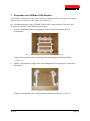
7 Packing UltiMate 3000 Devices
All UltiMate 3000 Devices except for Solvent Racks, Fraction Collectors, and Open
Autosamplers. For information about how to pack these devices, see pages 15 and following
pages.
The shipping containers for some UltiMate 3000 devices have been changed. Follow the steps
that are appropriate for your type of packaging.
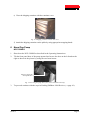
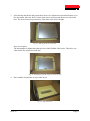
• Newer shipping containers have two foam inserts, one of which covers the entire bottom of
the container and the other one protects the device from above:
Fig. 15: Foam insert, here covering the bottom of the shipping container
Follow the steps in Packaging with Foam Inserts (→ page 11).
• Previous shipping containers have an outer box, foam braces, and an inner box.
Fig. 16: Outer box with foam braces
Follow the steps in Packaging with Foam Braces (→ page 12).

Seite 11 Page 11
7.1 Packaging with Foam Inserts
Note for Corona Veo detector packaging: The foam inserts of the packaging for the Corona
Veo detector differ from the foam inserts shown in the pictures below. However, the
packaging procedure for the detector corresponds to the procedure described in this section.
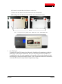
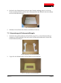
1. Place the box on the floor, and then place one foam insert into the box.
Fig. 17: Bottom foam insert
2. After having shut down and prepared the device for shipment as described further up in
this document, place the device on the foam insert and place the second foam insert on
top of the device.
Fig. 18: Device with foam insert on top
3. Only RS, SD, and BM pumps, NCP-3200RS, ECD-3000RS detectors
and all VWD-3x00, DAD-3000, and MWD-3000 detectors
Place the additional spacer (box or foam insert) on the foam insert on top of the device.

Seite 12 Page 12
4. Place the accessories box (with or without accessories, depending on whether you need to
return them, too) on the upper foam insert and fill the free space by using the two
cardboard stripes.
Fig. 19: Accessories box
5. Close and seal the box by using adhesive tape.
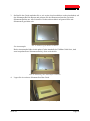
7.2 Packaging with Foam Braces
1. Place the larger box on the floor, place the foam braces along the left and right side in the
box, and place the inner box between the braces.
Fig. 20: Outer box with foam braces
2. Place the foam insert on the bottom of the inner box.
Fig. 21: Inner box with foam insert

Seite 13 Page 13
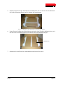
3. After having shut down and prepared the device for shipment as described further up in
this document, place the device on the foam insert and surround the device with foam
bars. The device must be protected by foam bars to the device height.
Fig. 22: Placing the device in the box
Only autosamplers
The autosampler is higher than other devices of the UltiMate 3000 series. Therefore, two
foam inserts are required on each side.
Fig. 23: Autosampler placed and protected in the box
4. Place another foam insert on top of the device.
Fig. 24: Top foam insert
2x
2x 2x
2x

Seite 14 Page 14
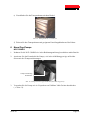
5. Close and seal the inner box by using adhesive tape. Place two foam braces along the
edges of the inner box.
Fig. 25: Outer box with completely packed inner box
6. Place the accessories box (with or without accessories, depending on whether you need to
return them, too) between the braces.
Fig. 26: Outer box completely packed with inner and accessories boxes
7. Close and seal the outer box by using adhesive tape.
Accessories box

Seite 15 Page 15
8 Solvent Racks
SR-3000 and SRD-3x00
1. Shut down the solvent rack as described in the Operating Instructions.
2. Push the foam braces onto the four corners of the solvent rack, and then place the rack in
the inner box.
Fig. 27: Solvent rack with foam braces
3. Depending on whether the Solvent Rack is shipped with or without solvent bottles:
♦ Shipping the Solvent Rack with solvent bottles
Place the foam insert for the bottles (1) in the bottle tray of the Solvent Rack, place the
bottles in the recesses provided in the insert, and then secure the bottle necks in the
second foam insert (2).
Fig. 28: Securing the bottles (here for an SRD-3600)
♦ Shipping the Solvent Rack without solvent bottles
Place the foam insert for the bottles (1) in the bottle tray of the Solvent Rack, place the
second foam insert (2) onto the first one.
2
1

Seite 16 Page 16
4. Place the accessories box (with or without accessories, depending on whether you need to
return them, too) on the foam insert. If necessary, fill the empty space between the
Solvent Rack and the top of the box with packing material to prevent the Solvent Rack
from moving inside the box during transit.
Fig. 29: SRD packed with accessories box in the shipping container
5. Close and seal the box by using adhesive tape.
9 Automated Fraction Collector
AFC-3000
1. Shut down the fraction collector as described in the Operating Instructions.
2. Before shipping the AFC, you have to remove the valve unit. If the valve unit needs to be
returned, use the packaging in which the valve unit was shipped.
3. Surround the AFC with the protective wrap and place the device in the box.
4. Place the two foam spacers on the sides of the AFC as shown in the picture and fill the
empty space between the fraction collection arm and the spacers with packing material to
protect the arm during transit.
Fig. 30: AFC placed in the shipping container
5. Close and seal the box by using adhesive tape.

Seite 17 Page 17
10 XRS Open Autosamplers
OAS-3300TXRS and OAS-3600TXRS
1. Shut down the autosampler as described in the Operating Instructions.
2. Depends on whether you want to return the autosampler system or only a component or
sub-assembly:
a) To return a component or sub-assembly, take the appropriate steps to remove the
component or sub-assembly by following the related installation steps in the Operating
Instructions in the reverse order.
b) To return the autosampler system, disassemble the autosampler by following the
assembling steps in the Operating Instructions in the reverse order.
3. The pictures show how the main components should be arranged in the shipping boxes.
Seal the boxes by using adhesive tape.
Important: If loose material (foam or similar items) is used to fill up a shipping box, it is
mandatory to protect the components and sub-assemblies in a plastic bag. Removing the
loose material and cleaning the components is very time consuming.
♦ For the basic autosampler system (that is, the x-, y-axes assembly, control terminal,
injection unit (z-axis), basic autosampler power supply, safety guard, connecting cables,
and miscellaneous accessory parts) - see further down.
♦ For the stack cooler - see page 19
♦ For the DLW option - see page 19
♦ For the table and other accessories - see page 20
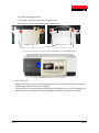
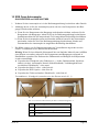
Shipping box — basic autosampler system (usually box 1)
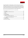
Fig. 31: Packing the shipping box (basic autosampler) - 1
No. Description
1 Foam inserts
2 Box for power supply (basic autosampler system)
3 x-, y-axes assembly
2
1 3

Seite 18 Page 18
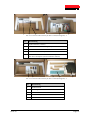
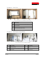
Fig. 32: Packing the shipping box (basic autosampler) - 2
No. Description
1 Injection unit (z-axis)
2 Foam insert holding the injection unit
3 Space for accessories box
3 3-valve housing with injection valve
4 Space for miscellaneous connecting cables and
additional autosampler leg (here hidden by the cables)
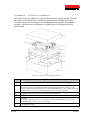
Fig. 33: Packing the shipping box (basic autosampler) - 3
No. Description
1 Control terminal
2 Mounting bracket for control terminal
3 Safety guard
4 Sample trays (VT54)
5 Reservoir tray
1 2 3 5 4
1 2
3 3 4

Seite 19 Page 19
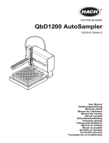
Shipping box — Stack cooler
Fig. 34: Packing the shipping box (stack cooler)
No. Description
1 Empty box (for packaging purposes only)
2 Foam inserts
3 Stack cooler
4 Box for power supply (stack cooler)
5 Miscellaneous foam inserts
Shipping box — DLW (Dynamic Load and Wash)
Fig. 35: Packing the shipping box (DLW)
No. Description No. Description
1 Miscellaneous DLW accessories 2 Syringe
3 Wash liquid reservoirs 4 Wash station
5 Syringe holder assembly 6 Pump module
3 4 2 1 5 5
5 4 6 1 3 2
Seite wird geladen ...
Seite wird geladen ...
Seite wird geladen ...
Seite wird geladen ...
Seite wird geladen ...
Seite wird geladen ...
Seite wird geladen ...
Seite wird geladen ...
Seite wird geladen ...
Seite wird geladen ...
Seite wird geladen ...
Seite wird geladen ...
Seite wird geladen ...
Seite wird geladen ...
Seite wird geladen ...
Seite wird geladen ...
Seite wird geladen ...
Seite wird geladen ...
Seite wird geladen ...
Seite wird geladen ...
Seite wird geladen ...
Seite wird geladen ...
-
 1
1
-
 2
2
-
 3
3
-
 4
4
-
 5
5
-
 6
6
-
 7
7
-
 8
8
-
 9
9
-
 10
10
-
 11
11
-
 12
12
-
 13
13
-
 14
14
-
 15
15
-
 16
16
-
 17
17
-
 18
18
-
 19
19
-
 20
20
-
 21
21
-
 22
22
-
 23
23
-
 24
24
-
 25
25
-
 26
26
-
 27
27
-
 28
28
-
 29
29
-
 30
30
-
 31
31
-
 32
32
-
 33
33
-
 34
34
-
 35
35
-
 36
36
-
 37
37
-
 38
38
-
 39
39
-
 40
40
-
 41
41
-
 42
42


Thermo Fisher Scientific Dionex UltiMate 3000 Series Bedienungsanleitung
- Typ
- Bedienungsanleitung
in anderen Sprachen
Verwandte Artikel
-
 Thermo Fisher Scientific UltiMate 3000 Series Installationsanleitung
-
 Thermo Fisher Scientific Surveyor Plus Bedienungsanleitung
-
 Thermo Fisher Scientific Vanquish Neo System VN-A10, VN-C10, VN-P10, VN-S10 Bedienungsanleitung
-
 Thermo Fisher Scientific Herasafe 2025 Bedienungsanleitung
-
 Thermo Fisher Scientific Biological Safety Cabinet MSC-Advantage Bedienungsanleitung


Andere Dokumente
-
Fritsch Laser Particle Sizer ANALYSETTE 22 NT Bedienungsanleitung
-
 Hach QbD1200 AutoSampler Benutzerhandbuch
-
 Hach QbD1200 AutoSampler Benutzerhandbuch
-
MAHA MBT LON Bedienungsanleitung
-
 Plasmon LF 6602 Benutzerhandbuch
-
HP Latex 3000 Printer Benutzerhandbuch
-
HP Latex 3800 Jumbo Roll Solution Benutzerhandbuch
-
SBC PCD2.M5xxx Bedienungsanleitung
-
Binder FED 400 Bedienungsanleitung


