Seite wird geladen ...

Revision 5.3 August 2013 © Thermo Fisher Scientific Inc.
Doc. No. 4820.4003 All rights reserved.
All trademarks are property of Thermo Fisher Scientific Inc. and its subsidiaries.
Drain Tubing
(Part No. 6040.0005)
for UltiMate 3000 Systems
Installation Instructions
For instructions in English, see page 1.
Drainage
(Best.-Nr. 6040.0005)
für UltiMate 3000-Systeme
Installationsanleitung
Die deutsche Anleitung finden Sie ab Seite 7.
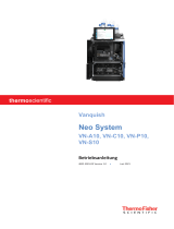
Autosampler
Column Compartment
Pump
Solvent Rack
Detector

Seite 1 Page 1
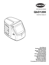
To discharge liquid leaks that might have accumulated in the interior, all Thermo Scientific™
Dionex™ UltiMateTM 3000 system modules have a drain port at the bottom right of the module.
Some modules have additional ports; for example, the autosamplers of the UltiMate 3000 series
have two or three ports, depending on the autosampler type.
Fig. 1: Drain ports (here on an autosampler with sample thermostatting option)
The drain kit includes all components that are required to discharge liquids from an
UltiMate 3000 system to waste. The system setup determines which parts need to be installed.
Thus, not all parts included in the kit may be required for your individual setup.
Description Part No.
Drain kit for UltiMate 3000 systems, including:
5 Y pieces, 4 T pieces, 9 elbows, 4 tubing clips,
1 connecting tube (20 mm), and 6 m tubing (11.4 mm x 8.4 mm O.D. x I.D.)
6040.0005
Note: If the UltiMate 3000 system includes two detectors, an additional T piece may be required. The T
piece is provided in the accessories kit of the UltiMate 3000 DAD, MWD, FLD and ECD-RS detectors
and in the accessories kit of the Corona™ Veo™ (RS) detectors.
The installation procedure refers to the drain tubing for a standard analytical UltiMate 3000
system as shown on the cover page of these instructions. However, the steps are similar for all
other systems and setups.
Refer also to the operating instructions for the UltiMate 3000 system modules; they may
provide additional information.
1. Cut the tubing from the kit to suitable lengths.
For the system setup shown on the cover page of these instructions, Thermo Fisher
Scientific recommends cutting the tubing to the lengths indicated in the table. For all other
systems and setups, adapt the tubing lengths as required.
No. Tubing between Length (mm)
1 Solvent rack and first Y piece
UltiMate 3000 pump
UltiMate 3000 RS, SD, or BM pump
280
250
2 Pump and
first
Y piece 130
3 First and second Y piece 310
4 Autosampler front ports and second Y piece 120
5 Autosampler rear port and third Y piece 150
6 Second and third Y piece 50
7 Third and fourth Y piece 90
Only on autosamplers with
sample thermostatting
option

Seite 2 Page 2
No. Tubing between Length (mm)
8 Column compartment and fourth Y piece 130
9 Fourth Y piece and edge of the lab bench Depends on the
installation site
10 Detector and edge of the lab bench
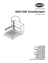
2. Connect the drain tubing as shown in the picture.
You can easily push the drain tubing into the connecting pieces with your hand (no tools
required). Push the tubing into the connecting piece as far as it goes in to establish a self-
sealing connection. When installing the tubing, do not bend it against the preformed bending
direction.
Fig. 2: Example of a drain system installation
(red: Y pieces, pink: elbows, green: T pieces)
a) Install an elbow and tubing of suitable length at the drain ports of solvent rack and pump.
Connect the tubing from solvent rack and pump by using an Y piece.

Seite 3 Page 3
b) To connect the two front ports of the autosampler, push an elbow and T piece over the
metal connecting tube to stabilize the connection between the two.
Fig. 3: Push an elbow and T piece onto the connecting tube
Install another elbow on the rear port of the autosampler (only autosamplers with
thermostatting option). Connect the autosampler ports by using two Y pieces as shown in
Fig. 2.
c) Column compartment without valves installed to the sides of the enclosure
Use an elbow and Y piece to connect the port on the column thermostat to the drain
system.
Column compartment with one or two valves installed to the sides of the enclosure
Column switching valves that are installed to the sides of the column compartment have
their own drain system that is installed and connected to the drain port of the column
compartment together with the valves (→ Installation Instructions for the valves). Use
another Y-piece to connect the valve drainage and drain port of the column compartment
to the drain tubing of the UltiMate 3000 system.
Fig. 4: Valve drainage connected to UltiMate 3000 drain system
T piece
Elbow
Connecting tube
Valve drainage connected
to the column compartment
Connection port for
UltiMate
3000 drain system
Y piece of the UltiMate 3000
drain system

Seite 4 Page 4
d) Connect long enough tubing to the last Y piece to reach the edge of the lab bench.
Connect an elbow and tubing to the drain port of the detector and direct the tubing
separately to the waste container (see picture). The Corona Veo (RS) detector has two
drain ports, which must be directed to the waste separately. For details, refer to the
operating instructions of the detector.
If the UltiMate 3000 system includes two detectors, an additional T piece may be
required. The T piece is provided in the accessories kit of the UltiMate 3000 DAD,
MWD, FLD and ECD-RS detectors and in the accessories kit of the Corona Veo (RS)
detectors.
Fig. 5: Separate drain tubing connected to the detector
Observe the following:
♦ When connecting the drain tubing, the tubing must remain below the drain port.
Make sure that the tubing is not bent or kinked at any point. If the tubing is
above the drain port, liquid may flow back into the interior and cause damage to
the instrument.
♦ If the lab bench has a front raised lip higher than 1.5 cm (0.6 in), the liquid
cannot be directed over the elevated edge. In this case, route the tubing to the
rear of the lab bench as shown in the picture and direct the liquid into an
appropriate waste container.
Fig. 6: Alternative routing of the drain tubing

Seite 5 Page 5
3. Place the free ends of the drain tubing into an appropriate waste container.
To avoid liquid backflow into the interior of the module, connect a T piece to an elbow as
shown in the picture. The T piece with the opening facing upward helps removing air from
the drain system and thus prevents liquid from flowing back into the interior of the modules.
Fig. 7: Routing the drain tube to waste
Important: When routing the drain tubing to waste, observe the following to
prevent the liquid from flowing back into the interior (and thus to
prevent a possible leak alarm in the detector):
♦ The waste container must be below the system to allow the liquid to
flow off.
♦ The free end of the tubing inside the waste container must be above
the liquid level in the container at any time. Shorten the tubing if
required.
Fig. 8: Free end of the tubing in the waste container
4. Use the four self-adhesive clips to fix the drain tubing to the sides of the system modules.
Attach the adhesive side of a clip to the side panel of the module and insert the tubing
into the clip.
Fig. 9: Tubing clip
T piece
Elbow

Seite 6 Page 6
5. Verify that the seal washing liquid is discharged properly.
RS, SD, and BM pumps
Remove the detector of the seal wash system and fill the drain port of the seal wash system
several times with HPLC-grade water, as shown in the picture, until the liquid exits the drain
port at the bottom right of the pump. Verify that the liquid is discharged properly to waste.
NCS-3500RS and NCP-3200RS
Remove the seal wash tubing from the detector of the seal wash system, connect silicone
tubing to the connection port, and fill in HPLC-grade water, as shown in the picture, until
the liquid exits the drain port at the bottom right of the module. Verify that the liquid is
discharged properly to waste.
Fig. 10: Filling liquid into the seal wash system (examples)
(left: RS, SD, and BM pumps; right: NCS-3x00RS)
If the liquid is not discharged properly, modules that are located under the pump or
NCS/NCP in the UltiMate 3000 system stack, may suffer severe damage from the liquid
leaving the drain port.

Seite 7 Page 7
Alle Thermo Scientific™ Dionex™ UltiMateTM 3000-Geräte verfügen rechts unterhalb des
Gerätes über einen Ablauf, über den Flüssigkeiten aus dem Geräteinneren in den Abfall
abgeleitet werden können. Einige Geräte verfügen über zusätzliche Abläufe, beispielsweise die
UltiMate 3000 Autosampler, die je nach Gerätetyp über zwei oder drei Abläufe verfügen
können.
Abb. 1: Drainage-Abläufe (hier Autosampler mit Probenthermostatisierung)
Das Drainage-Kit enthält alle Komponenten, die zur Ableitung der Flüssigkeiten eines
UltiMate 3000-Systems in den Abfall erforderlich sind. Welche Teile benötigt werden, hängt
dabei vom Systemaufbau ab. Daher müssen nicht unbedingt alle im Kit enthaltenen Teile für
das jeweilige System verwendet werden.
Beschreibung Best.-Nr.
Drainage-Kit für UltiMate 3000-Systeme, bestehend aus:
5 Y-Stücken, 4 T-Stücken, 9 L-Stücken, 4 Schlauchclips,
1 Verbindungsrohr (20 mm) und 6 m Schlauch (11,4 mm AD x 8,4 mm ID)
6040.0005
Hinweis: Wenn das UltiMate 3000-System zwei Detektoren enthält, wird gegebenenfalls ein weiteres
T-Stück benötigt. Dieses finden Sie im Gerätezubehör der DAD-, MWD-, FLD- und ECD-RS-Detektoren
und im Zubehör zu Corona™ Veo™ (RS)-Detektoren.
Die nachfolgende Beschreibung bezieht sich auf die Installation der Drainage für ein
analytisches UltiMate 3000-Standardsystem in dem auf der Titelseite dargestellten System-
aufbau. Sie gilt jedoch analog für alle anderen Systeme und Systemaufbauten.
In den Bedienungsanleitungen zu den einzelnen Modulen eines UltiMate 3000-Systems
finden Sie gegebenenfalls weitere Hinweise.
1. Schneiden Sie die Schläuche aus dem Kit auf geeignete Längen zu.
Für den auf der Titelseite abgebildeten Systemaufbau empfiehlt Thermo Fisher Scientific
die in der Tabelle genannten Längen. Für andere Systeme und Aufbauten sind die Längen
entsprechend anzupassen.
Nr. Schlauch zwischen Länge (mm)
1 Solvent Rack und erstem Y-Stück
UltiMate 3000-Pumpe
UltiMate 3000 RS/SD/BM-Pumpe
280
250
2 Pumpe und erstem Y-Stück 130
3 erstem und zweiten Y-Stück 310
4 Autosampler
vorne
und
zweitem
Y-Stück 120
5 Autosampler hinten und drittem Y-Stück 150
Nur Autosampler mit
Probenthermostatisierung

Seite 8 Page 8
Nr. Schlauch zwischen Länge (mm)
6 zweitem und drittem Y-Stück 50
7 drittem und viertem Y-Stück 90
8 Säulenthermostat und viertem Y-Stück 130
9 viertem Y-Stück und Tischkante Abhängig von
Gegebenheiten
10 Detektor und Tischkante
2. Verbinden Sie die Ablaufschläuche wie in der Abbildung gezeigt.
Die Schläuche können leicht per Hand in die Verbindungsstücke eingesteckt werden.
Schieben Sie den Schlauch bis zum Anschlag in das Verbindungsstück ein; die Ver-
bindungen sind dann selbstdichtend. Biegen Sie die Schläuche beim Einsetzen nicht
entgegen der durch den Transport "vordefinierten" Krümmung.
Abb. 2: Montagebeispiel für eine Systemdrainage (rot: Y-Stücke, pink: L-Stücke, grün: T-Stücke)
a) Befestigen Sie am Ablauf des Solvent Racks und der Pumpe je ein L-Stück mit dem
passend abgelängten Schlauch. Verbinden Sie Solvent Rack und Pumpe mit Hilfe eines
Y-Stücks.

Seite 9 Page 9
b) Stecken Sie für den Anschluss der beiden vorderen Abläufe am Autosampler ein L-Stück
und ein T-Stück auf das Verbindungsrohr, um die Verbindung zu stabilisieren.
Abb. 3: L-Stück und T-Stück auf Verbindungsrohr stecken
Befestigen Sie am hinteren Ablauf des Autosamplers ein weiteres L-Stück (nur bei
Autosamplern mit Thermostatisierung). Verbinden Sie die Abläufe wie in Abb. 2 gezeigt
über zwei weitere Y-Stücke.
c) Säulenthermostat ohne Ventile am Gehäuse installiert
Schließen Sie den Ablauf des Säulenthermostaten ebenfalls mit Hilfe eines L-Stücks und
eines Y-Stücks an die Systemdrainage an.
Säulenthermostat mit einem oder zwei Ventilen am Gehäuse installiert
Säulenschaltventile, die am Gehäuse des Säulenthermostaten installiert werden, verfügen
über eine eigene Drainagevorrichtung, die zusammen mit den Ventilen installiert und an
den Säulenthermostaten angeschlossen wird (→ Installationsanleitung der Ventile).
Verbinden Sie die Ventildrainage am Ablaufport des Säulenthermostaten mit dem Y-
Stücks der Systemdrainage.
Abb. 4: Anschluss der Ventildrainage an die Drainage für das UltiMate 3000-System
T-Stück
L-Stück
Verbindungsrohr
Ventildrainage am Ablauf
des Säulen
thermostaten
angeschlossen
Anschlussport UltiMate 3000
Systemdrainage
Y-Stück der UltiMate 3000
Systemdrainage

Seite 10 Page 10
d) Schließen Sie an das letzte Y-Stück einen Schlauch bis zur Tischkante an. Führen Sie
einen weiteren Schlauch vom Ablauf des Detektors über ein L-Stück separat in den
Abfall (siehe Abbildung). Der Corona Veo (RS)-Detektor besitzt zwei Abläufe, die
separat in den Abfall geleitet werden müssen. Weitere Informationen finden Sie in der
Bedienungsanleitung für den Detektor.
Wenn das UltiMate 3000-System zwei Detektoren enthält, wird gegebenenfalls ein
weiteres T-Stück benötigt. Dieses finden Sie im Gerätezubehör der DAD-, MWD-, FLD-
und ECD-RS-Detektoren der UltiMate 3000-Serie sowie im Zubehör zu den Corona Veo
(RS)-Detektoren.
Abb. 5: Separater Drainageanschluss am Detektor
Beachten Sie die folgenden Hinweise:
♦ Achten Sie bei der Verlegung der Ablaufschläuche darauf, dass diese weder
geknickt sind, noch an irgendeiner Stelle höher liegen als der Anschlussport. Bei
Missachtung kann es zu einem Flüssigkeitsrückstau und damit zu einer
Beschädigung des Geräts kommen.
♦ Wenn der Labortisch vorne eine erhöhte Kante von mehr als 1,5 cm aufweist,
kann die Flüssigkeit nicht über diese Erhebung abgeleitet werden. Führen Sie
den Schlauch in diesem Fall wie unten gezeigt zur hinteren Tischkante und
leiten Sie die Flüssigkeit von dort in einen Abfallbehälter.
Abb. 6: Alternative Führung der Drainage

Seite 11 Page 11
3. Führen Sie die Ablaufschläuche in einen geeigneten Abfallbehälter.
Um die Flüssigkeit sicher über die Kante des Labortisches zu abzuleiten, stecken Sie ein
T-Stück auf ein L-förmiges Verbindungsstück wie in der Abbildung gezeigt. Das T-Stück
mit der Öffnung nach oben bewirkt eine Entlüftung des Drainagesystems und verhindert
einen Flüssigkeitsrückstau durch Luftblasen im Ablaufsystem.
Abb. 7: Ableitung der Flüssigkeit in den Abfall
Vorsicht: Beachten Sie bei der Verlegung der Ablaufschläuche in den Abfall un-
bedingt folgende Hinweise, um einen Flüssigkeitsrückstau (und damit
möglicherweise einen Leak-Alarm im Detektor) zu vermeiden:
♦ Der Abfallbehälter muss sich unterhalb des Systems befinden, damit
die Flüssigkeit ungehindert abfließen kann.
♦ Das Schlauchende, das in den Abfallbehälter geführt wird, muss sich
zu jeder Zeit über dem Flüssigkeitsniveau befinden. Kürzen Sie, falls
erforderlich, den Ablaufschlauch entsprechend.
Abb. 8: Position des Schlauchendes im Abfallbehälter
4. Verwenden Sie die vier selbstklebenden Clips, um die Ablaufschläuche an den Seiten-
wänden der Geräte zu fixieren. Kleben Sie den Clip an die Seitenwand des Geräts und
klemmen Sie den Schlauch mit dem Clip fest.
Abb. 9: Schlauchclip
T-Stück
L-Stück

Seite 12 Page 12
5. Vergewissern Sie sich, dass die Hinterspülflüssigkeit ungehindert abfließt.
RS-, SD- und BM-Pumpen
Ziehen Sie den Detektor der Hinterspülung nach oben heraus und füllen Sie mehrfach
Wasser in HPLC-Qualität, wie unten gezeigt, in den Abflussport der Hinterspülung ein, bis
die Flüssigkeit am Ablauf rechts unterhalb der Pumpe austritt. Vergewissern Sie sich, dass
die Flüssigkeit ungehindert abfließt.
NCS-3500RS und NCP-3200RS
Stecken Sie den Schlauch der Hinterspülung am Detektor ab, stecken Sie ein Stück Silikon-
schlauch auf den Anschlussport und füllen Sie, wie unten gezeigt, Wasser in HPLC-Qualität
ein, bis die Flüssigkeit am Ablauf rechts unterhalb des Moduls austritt. Vergewissern Sie
sich, dass die Flüssigkeit ungehindert abfließt.
Abb. 10: Befüllen der Hinterspülung (Beispiele)
(links: RS-/SD-/BM-Pumpe; rechts: NCS-3x00RS)
Wenn die Flüssigkeit nicht ungehindert abfließt, können Geräte, die sich unterhalb der
Pumpe bzw. des NCS/NCP im System befinden, durch Lösungsmittel beschädigt werden.
/