Knauer Smartline Manager 5000 Benutzerhandbuch
- Typ
- Benutzerhandbuch

S
S
m
m
a
a
r
r
t
t
l
l
i
i
n
n
e
e
M
M
a
a
n
n
a
a
g
g
e
e
r
r
5
5
0
0
0
0
0
0
M
M
a
a
n
n
u
u
a
a
l
l
/
/
H
H
a
a
n
n
d
d
b
b
u
u
c
c
h
h
V 7602 10/2007
Wissenschaftliche Gerätebau
Dr. Ing. Herbert Knauer GmbH
Hegauer Weg 38
D - 14163 Berlin, Germany
Tel.: +49 (0)30 809 727 0
Fax.: +49 (0)30 801 50 10
E-Mail: [email protected]
Internet: www.knauer.net

CONTENTS
Using this Manual 4
Conventions in this Manual 4
Importend Hint 4
SOP´s in this manual 5
Smartline Manager 5000 5
Compact Versatility 5
Low Pressure Gradient (LPG) Block 6
General Description 6
Installation 6
Electrical Connection with the Smartline Pump 1000 7
Eluent Connection with the Smartline Pump 1000 7
Technical Data 9
Vacuum Degasser Unit 10
Introduction 10
Working Principle 10
Principles of degassing using Teflon AF
®
membranes 10
General Description 11
Unpacking the Degasser Unit 11
Spare parts and accessories 12
Technical Data and Specifications 13
Connection 14
Front Panel Connections 14
Front Panel LEDs 14
Rear Panel Connections 15
System Requirements 16
Solvents/Mobile Phase 16
Chemical compatibility 16
Space Requirements 16
Electrical Power Requirements 16
Installation 17
Installing the Degasser Unit 17
Connecting the Tubings 17
Connecting the Vacuum Degasser in a Smartline LPG System 18
Operation 20
Powering up the Vacuum Degasser 20
Extending the degassing flow rate range 21
Shutdown 21
Short-term Shutdown (Overnight and Weekends) 21
Long-term Shutdown 22
Maintenance 22
Preventative Maintenance 22
Routine Maintenance 22
Smart Leak Detection 23
Troubleshooting 23

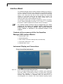
Interface Modul 24
Contents of the accessory kit for the Smartline Manager 5000 Interface Module 24
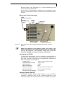
Instrument Display and Connections 24
Front view of the instrument 24
Back panel of the instrument 25
Analog Inputs (AN.IN) 25
Analog Outputs (AN.OUT) 25
Digital Inputs (DIG.IN) 26
Digital Outputs (DIG.OUT) 26
RS-232 Interface 26
Connecting the Smartline Manager 5000 Interface Module 26
Power supply 26
Smartline Manager 5000 Interface Module on the PC (RS-232) 27
Analog Inputs 27
Analog Outputs 27
Digital Connections 27
Installation of the WAGO service cable 27
Example of the Cabling 28
Warranty statement 55
Declaration of conformity 56
INHALT
Hinweise zum Gebrauch des Handbuchs 29
Konventionen in diesem Handbuch 29
Wichtiger Hinweis 29
SOP´s in diesem Handbuch 30
Smartline Manager 5000 30
Vielseitigkeit auf kleinstem Raum 30
Niederdruckgradienten (NDG) Block 31
Allgemeine Beschreibung 31
Installation 31
Elektrische Verbindung mit der Smartline Pumpe 1000 32
Eluenten Verbindung mit der Smartline Pumpe 1000 32
Technische Daten 34
Vacuum Degasser Einheit 35
Einführung 35
Funktionsweise 35
Entgasungsprinzip der Teflon AF
®
Membran 35
Allgemeine Beschreibung 36
Auspacken des Degassers 36
Ersatzteile und Zubehör 37
Technische Daten und Spezifikation 38
Anschluss und Inbetriebnahme 39
Anschlüsse an der Vorderseite 39
LED Anzeigen auf der Vorderseite 39
Anschlüsse an der Rückseite 41

Systemanforderungen 41
Lösungsmittel/Mobile Phase 41
Chemische Beständigkeit 42
Platzbedarf 42
Stromversorgung 42
Installation 42
Installation des Degassers 42
Schlauchverbindungen 43
Anschluss des Degassers in dem Smartline NDG System 45
Bedienung 45
Einschalten des Degassers 45
Erweiterung der Entgasungskapazität 47
Abschaltung 47
Abschaltung für einen kurzen Zeitraum 47
Abschaltung für einen längeren Zeitraum 47
Wartung 48
Vorbeugende Wartung 48
Regelmäßige Wartung 48
Leckdetektion 48
Fehlersuche 49
Interface Modul 50
Inhalt des Beipacks zum Smartline Manager 5000 Interface Modul 50
Geräteansichten und Anschlüsse 50
Vorderansicht des Gerätes 50
Rückseite des Gerätes 51
Analoge Eingänge (AN.IN) 51
Analoge Ausgänge (AN.OUT) 51
Digitale Eingänge (DIG.IN) 52
Digitale Ausgänge (DIG.OUT) 52
RS232 Schnittstelle 52
Anschließen des Smartline Manager 5000 Interface Moduls 52
Stromversorgung 52
Smartline Manager 5000 Interface Modul an PC (RS232) 53
Analogeingänge 53
Analogausgänge 53
Digitalverbindungen 53
Montage der WAGO-Anschlussleitungen 53
Verkabelungsbeispiel 54
Gewährleistungsbedingungen 55
Konformitätserklärung 56

4 Using this Manual
Using this Manual
Conventions in this Manual
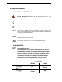
Special Warnings are indicated by the marginal warning sign and
printed in bold letters.
The marginal lamp symbol indicates helpful advice’s.
Important Hints are marked by the marginal hand symbol.
Arrows in an outlined form like this example used in block diagrams,
indicate an automatic program run and change to the next line without the
necessity of manual interventions.
Arrows like this, used in block diagrams, indicate that the user is asked to
press the corresponding arrow keys
¾ ¿ ½ À The triangles symbolize the use of corresponding arrow keys.
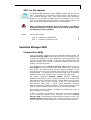
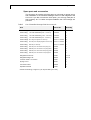
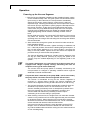
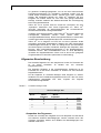
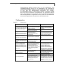
Importend Hint
Dear KNAUER customer,
if you are going to use a Smartline Pump 1000 with low pressure
gradient, please check whether or not the serial numbers of your
Smartline Pump 1000 and your Smartline Manger 5000 fit together.
If the serial numbers do not fit according the table below, please
contact KNAUER or your local KNAUER representative to make
shure that the respective valve settings were / will be changed.
Otherwise the low pressure gradient may not work properly.
Smartline Manager 5000 with LPG
Serial Number
≥ 81349
< 81349
Smartline Pump 1000
Serial Number
≥ 80713
OK
Settings need to be
changed
Smartline Pump 1000
Serial Number
< 80713
Settings need to be
changed
OK

Smartline Manager 5000 5
SOP´s in this manual
The Standard Operating Procedures (SOP) provided with this manual
offer a convenient way of structuring complex tasks in the operation of
your Smartline Manager 5000. They include step-by-step instructions
leading the user through all routine tasks during operation. They can be
used for documentation purposes and be copied, applied signed, and
filed in order to document the performance of the instrument.
Please operate the instrument and all accessories according to
instructions and SOP´s in this manual. This ensures proper results
and longevity of your equipment.
Table 1 SOP´s in this manual
SOP 1
Selecting a Gradient Mode 8
SOP 2 Selection of operation mode: 8
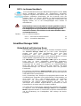
Smartline Manager 5000
Compact Versatility
As the most flexible member of the new Smartline instrument family, the
Smartline Manager 5000 stands apart not only for its versatility, but for
its technical specifications as well. Adaptable to the requirements of the
customer, the Smartline Manager can be optionally equipped with a low
pressure gradient (LPG) module, a degasser module and an interface
module. You have the choice!
The combination of the Smartline Manager 5000 (equipped with the
LPG module) with the Smartline Pump 1000 provides for a quaternary
LPG system. The maximum flow rate per channel, depending on the
pump head, can reach up to 50 ml/min. The valve block, made of highly
resistant PEEK, is controlled by the Smartline Pump 1000 and delivers
gradient mixtures of the highest precision over the entire flow range.
An optional integrated degasser module provides outstanding
performance through its use of a newly developed micro vacuum pump
while taking up only a minimum of space. The gas diffusion rate has been
improved by a factor of 200–300 times, thanks to a new amorphous
fluoro-polymer rather than a regular Teflon membrane. Excellent
chemical and physical stability parameters, as well as the reduction of the
internal chamber volume to less than 0.5 ml, are convincing features.
The Smartline degasser module is available for maximum flow rates of
either 10 ml/min or 50 ml/min.
In order to maintain the flexibility of being able to integrate additional
HPLC components outside of the Smartline series, the Smartline
Manager 5000 can optionally be equipped with an interface module. This
interface module enables highly precise data acquisition and provides
for the control of non-KNAUER devices over analog and relay outputs.

6 Low Pressure Gradient (LPG) Block
Low Pressure Gradient (LPG) Block
General Description
The LPG module in the Smartline Manager 5000 compliments the
Smartline Pump 1000 that creates a completely quaternary low pressure
gradient system. The flow range reaches up to 50 ml/min depending on
the pump head. A valve block made out of PEEK is controlled over the
Smartline Pump 1000 and delivers gradient mixtures with the highest
precision over the entire flow range.
The LPG Block in the Smartline Manager 5000 integrates and can be
equipped with a degasser and/or an interface module.
The LPG module in the Smartline Manager 5000 can only be operated in
combination with a Smartline Pump 1000. The Smartline Pump 1000
controls all electrical functions on the Smartline Manager 5000 and
provides the required electrical power supply. This is realized with a
connection cable (G0649). The connection cable is included in the
accessories for the Smartline Manager 5000.
The control of the LPG block can be obtained in the stand-alone mode
over the Smartline Pump 1000 or with ChromGate
®
or EuroChrom
®
software.
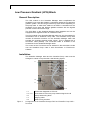
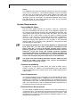
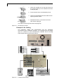
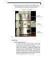
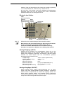
Installation
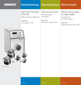
The Smartline Manager 5000 and the Smartline Pump 1000 must be
arranged in a tower on top the other. See following figures:
1.1
1.2
1.3
1.4
1.5
1.7
1.6
1.8
1.1 Connection degasser to LPG unit
1.2 – 1.5 Connections LPG unit to pump head mixing block A-D
1.6 Pump head mixing block
1.7 Purging outlet
1.8 Static mixing chamber
Figure 1 Arrangement of the Smartline Manager 5000 and Smartline Pump 1000 –
front view

Low Pressure Gradient (LPG) Block 7
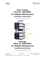
2.1
2.2
2.3
2.1 Manager connector
2.2 Pump connector
2.3 Connection cable
Figure 2 Arrangement of the Smartline Manager 5000 and the Smartline Pump
1000 – back panel view -
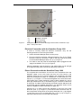
Electrical Connection with the Smartline Pump 1000
In order to correctly install the electrical connection, carry out the
following directions in the order given below:
1. Set the Smartline Manager 5000 over the pump.
2. Plug the included connection cable (accessories, Pos. {2.3} in Figure
2) into the “plug for connection” outlet on the rear panel of the pump
on the Smartline Manager 5000, Pos. {2.1} in Figure 2.
3. The cable on the rear panel of the Manager 5000 is plugged into the
“plug for the PUMP”, Pos. {2.1} in Figure 2.
When the Smartline 1000 is turned on, the yellow LEDs A to D will light
up for approximately three seconds and then they will shut off.
Eluent Connection with the Smartline Pump 1000
The required tube connections for the four LPG connections from the
degasser output to the LPG block and from the LPG block to the
Smartline Pump are cut to fit and included in the accessories, see spare
parts and accessories on page 12. Included are 4 PTFE tubes (0.11 m),
see Pos. {1.1} in Figure 1, to connect the degasser to the LPG block and 4
PTFE tubes (0.27 m blue marked (D), 0.28 m yellow marked (C), 0.29 m
black (B) marked and 0.30 m red marked (A)) to connect the LPG block
to the pump. The black PTFE bushings and seals must be attached to all
of the tubes (see the detailed description in the degasser section of this
manual, installation of tube connections on page 17).
Using the 0.11 m tubes connect the degasser to the input of the LPG
block “IN” (Pos. {1.1} in Figure 1). Then connect the LPG block “OUT” to
the low-pressure mixing block on the pump head (see Pos. {1.6} inFigure
1) using the 0.27 to 0.30 m tubes (see Pos. {1.2} to {1.5} in Figure 1).
Close the inputs that are not used with blind fittings.

8 Low Pressure Gradient (LPG) Block
Please make sure that the solvent bushings and the blind fittings
are tight. If they are not, the specifications of the LPG cannot be
guaranteed.
Set the desired low-pressure gradient in the pump’s setup menu
according to SOP 1and SOP 2.
SOP 1 Selecting a Gradient Mode
This SOP applies to the Smartline Pump 1000 Firmware Revision 1.0X.
Use this SOP for selecting a gradient mode.
1. Select „GRADIENT MODE“ in the SETUP Menu.
2. Select the desired mode of operation.
3. If you select either high or low pressure gradient (i. e. HPG or LPG)
you need to specify the channels of used solvents:
Low Pressure Gradient: Choose valves A to D
High Pressure Gradient: Choose pump names HPG A to HPG D
4. Move to the second line by pressing ¾ and choose valves A to D
(for LPG mode) or pumps actually present (for HPG mode) on the
corresponding positions by pressing ¿ or À. This selection will
apply for programs and define the number and names of solvents
used in any gradient.
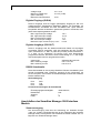
SOP 2 Selection of operation mode:
This SOP applies to the Smartline Pump 1000 Firmware Revision 1.0X.
1. Return to page GRADIENT MODE by pressing ¿.
2. Press ¾ and then ¿ to scroll through the gradient mode options
until LPG appears.
3. Use ¾ to position cursor in the second line.
4. Select ON or -- (off) at positions A, B, C and D for the solvent
channels in either mode you wish to use. The number of ONs
selected refers to all programs in the pumps memory.
5. At any position you can use ¿ or À to select ON.
6. Position cursor on next position, e. g. B and select ON .
7. Select three times ¾ to position cursor at the rhombus.
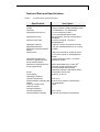
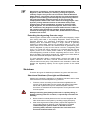
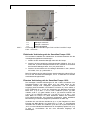
8. The display should appear as shown in Figure 3.
9. Leave this menu page with ½ to return to the main menu.
GRADIENT MODE: LPG
ON ON -- --
Load Edit Prog Flow Pressure Events
Prog Clear 0 [ml/min] [0.1 Mpa] off 0 on 1
2
Hold 0 Time %A %B %C %D
Run 1 [min]
Setup
GLP
Link
View
Figure 3 Example for a gradient setup with solvents A and B in all programs
The LPG block and the connection tubes should be rinsed with the
provided solvent and filled before they are used.
When the pump is turned off, the LPG block’s valves are closed. To
rinse the LPG block, set the flow rate to 0 ml/min and set the
pertinent mixture portion of the solvent for the respective valve to

Low Pressure Gradient (LPG) Block 9
100%. After this is completed, switch on the pump, so that the valve
can be opened.
Rinse the LPG block with the provided solvents by establishing a
connection on the pressure recorder’s vent capillary on the Smartline
Pump 1000 (see pos. {1.7} in Figure 1) using a syringe. Suction until there
are no more air pockets appear in the solution. Repeat this procedure for
all valves that will be used.
During operation the yellow “LEDs A to D” in front of the Smartline
Manager display the respective valve openings.
The accessory kit of the Smartline Manager 5000 includes a static
mixing chamber. It will be fixed at the front site of the pump, see
pos. {1.7} in Figure 1 on page 6. The mixing chamber enables an
optimum mixing of eluents in the range of 0.5 to 2.0 ml/min.
Technical Data
Eluent count: up to 4
Maximum flow per channel: 50 ml/min
Gradient range: 0–100%
Gradient gradation: 1% steps
Control: Through the Smartline Pump
1000 or ChromGate
®
or
EuroChrom
®
software

10 Vacuum Degasser Unit
Vacuum Degasser Unit
Introduction
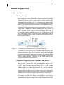
Working Principle
The Vacuum Degasser is a high-efficiency in-line module that removes
dissolved gasses from HPLC solvents. Its unique design assures reliable
continuous operation and the highest level of continuous performance
available. In the analytical version, up to four solvent lines may be
degassed simultaneously by one unit. The extremely low internal volume
(480 µl for the analytical version, 7.7 ml for the semipreparative version)
of each Teflon AF
®
channel provides for very quick equilibration and very
short startup times.
Inside the unit, the solvent flows through a short length of Teflon AF
®
tubing which is located in a vacuum chamber. Within this chamber a
partial vacuum is maintained by a constantly running, low RPM vacuum
pump. Dissolved gasses migrate across the tubing wall under a
concentration gradient produced by the vacuum as the solvent flows
within the coil (see Figure 4). Removed gasses are expelled, and the
vacuum is maintained at a constant, preset level by varying the vacuum
pump speed as needed.
Figure 4 Principle of gas permeability using a Teflon AF
®
membrane
A special port in the vacuum pump continually flushes the pump head
with a small “bleed” of air to remove any solvent vapors which may enter
the vacuum pump from the vacuum chamber. This air bleed eliminates
the need for any solenoid valves within the system. This patented design
results in zero vacuum “hysteresis”. Previous designs allowed the
vacuum chamber pressure to fluctuate, with the pump cycling on and
then off in response to the vacuum level.
Principles of degassing using Teflon AF
®
membranes
This relatively recent addition to the field of degassing has properties not
found in other fluoropolymers. The fully amorphous nature of this
fluoropolymer and its molecular structure creates a molecular level
porosity unlike the mechanically induced porosity in PTFE extruded
tubing. In addition, unlike the process used in extruding PTFE, no
extrusion agents are needed (like kerosene, etc.) which contaminate
mobile phases until they are extracted by the mobile phase over time.
Likewise, this molecular structure, combined with the very small surface
areas required to degas the mobile phase, reduces the possibility of
carryover from one solvent or mobile phase to another to virtually zero.
Teflon AF
®
is so non-polar that it is both solvophobic and hydrophobic.
This feature of Teflon AF
®
reduces the possibility of cross-channel
contamination from one channel to another, and when combined with the
ultra-low internal volumes of Teflon AF
®
channels needed for HPLC flow

Vacuum Degasser Unit 11
rates, all but eliminates this cross contamination concern by the
chromatographer. Teflon AF
®
has been used in certain optical systems
associated with HPLC for a few years without concern for normal HPLC
solvents. However, Teflon AF
®
is soluble in certain solvents (see page 16
Solvents/Mobile Phase) and must not be used to degas these types of
solvents.
Teflon AF
®
is permeable to some degree to water vapor whereas PTFE is
not. While the vacuum pump in the Vacuum Degasser contains internal
provisions for sweeping water or solvent vapor from the pump
continuously, it is possible that over time, high concentration buffers may
form crystals within the channel due to the loss of water within the
channel. The same precautions should be taken to prevent crystallization
within these channels as are taken for the HPLC pump. See the “Short-
term Shutdown” procedures.
General Description
The Smartline Degasser, analytical version, is available for flow rates up
to 10 ml/min per channel:
- Smartline Manager 5000 4 channel analytical degasser unit.
The semipreparative version of the Smartline Degasser can be used for
flow rates up to 50 ml/min:
- Smartline Manager 5000 2 channel semipreparative degasser unit.
The degasser unit is configured in the Smartline Manager 5000 either as
an individual module or in combination with a low pressure gradient mixer
for the Smartline Pump 1000 and / or with the Interface Module.
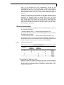
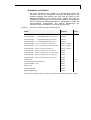
Table 2 Smartline Manager 5000
Smartline Manager 5000
Interface
Module
Degasser
Module
Analytical
Degasser
Module
Preparative
LPG Module Order No.
X X X A5311
X X A5312
X X A5313
X A5316
X X X A5320
X X A5321
X X A5322
X A5323
Unpacking the Degasser Unit
Carefully unpack the Smartline Manager 5000 with Vacuum Degasser
Unit and check for obvious signs of damage that may have occurred
during shipment. Immediately report any damage or missing items to your
Service Representative.

12 Vacuum Degasser Unit
Spare parts and accessories
The accessory kit contains all of the parts you will need for proper set up
and installation of the Smartline Manager 5000 unit with Degasser and
LPG unit. If you did not order the LPG option, you will only need part of
this accessory kit. To realise a simple installation the PTFE tubings are
precuted.
Table 3 List of Smartline Manager 5000 Accessory Kit
Item Article No. Quantity
PTFE tubing 1 m with eluent filter (
red - channel D
) G1440-1 1
PTFE tubing 1 m with eluent filter (
black – channel C
) G1440-2 1
PTFE tubing 1 m with eluent filter (
yellow – channel B
) G1440-3 1
PTFE tubing 1 m with eluent filter (
blue – channel A
) G1440-4 1
PTFE tubings 0.11 m (
from degasser to LPG-unit
) P9170 -> A0732* 4
PTFE tubing 0.14 m
(from semiprep-degasser to LPG-unit)
P9172 -> A0732* 1
PTFE tubing 0.44 m
(for HPG unit)
P9172 -> A0732* 1
PTFE tubing 0.27 m
(from LPG-channel D to pump) red
G0766 1
PTFE tubing 0.28 m
(from LPG-channel C to pump) black
G0767 1
PTFE tubing 0.29 m
(from LPG-channel B to pump) yellow
G0768 1
PTFE tubing 0.30 m
(from LPG-channel A to pump) blue
G0769 1
Flangeless ferrule 1/8” M1057 3 x 10
Flangeless fittings 1/8” M0435 3 x 10
Luerlock needle 1.5 x 50 mm M1551 1
Syringe 10 ml N0102 1
Connection cable G0649 1
Operator’s Manual V7602 1
* A0732 PTFE tubing, Length 3 m (can be precuted by the user)

Vacuum Degasser Unit 13
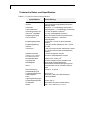
Technical Data and Specifications
Table 4 Technical Data and Specifications
Specification:
Description:
Dimensions 226 x 135 x 390 mm (W x H x D)
Weight 4.8 kg (complete Smartline Manager 5000)
Channels 1-4 independent / 1-2 independent
Degassing Flow Path I.D.
1.14 mm analytical version /
1.77 mm semipreparative version
Degassing Process
Gas permeation through a fluoropolymer
membrane
Maximum Flow Rate
10 ml/min analytical / 50 ml/min
semipreparative
Degassing Capacity ~2 ppm at 1 ml/min for analytical version
Degassing Efficiency < 0.5 ppm residual disolved O
2
at 1 ml/min
Degassing Channel Pressure
Rating
70 PSIG
Dead Volume
~480 µl per channel for analytical version
~7.7 ml per channel for semipreparative
version
Optimized Flow Rate (for
isocratic or gradient formed
50:50 methanol/water)
3 ml/min analytical version / 30 ml/min
preparative version
Materials contacting solvents PEEK, Glass-filled PTFE, Teflon AF
®
Solvent Applicability
universal, except hydrochloric acid
and halogenated carbohydrates
especially hexafluoro isopropanol (HFIP)
Power: via Smartline Pump 1000
Power Supply 90-260 V, 47–63 Hz
Operating Conditions:
Ambient Temperature 10 to 35 ºC
Ambient Relative Humidity (RH) 20 to 80 % RH (without condensation)
Altitude 0 to 2000 Meters
Indoor vs. Outdoor Use Indoor
Pollution Degree 2
Storage Conditions:
Ambient temperature -20 to +60 ºC
Ambient Relative Humidity 20 to 80% RH (without condensation)

14 Vacuum Degasser Unit
Connection
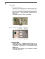
Front Panel Connections
Depending upon the model, there are 2 or 4 degassing channels. Pairs of
female ¼-28 connectors are located on the front of the Vacuum Degasser
module on the Smartline Manager 5000. These are the input and output
ports for running up to 4 solvent lines through the Vacuum Degasser.
Each channel has an input port and an output port on the same level. In
Figure 5 and Figure 6 the connection of both degasser units with LPG
unit is shown.
Plugs are provided to seal the ports of unused channels.
A
B
C
D
Flow
Degasser LPG Unit
Figure 5 Degasser Tubing Connection, analytical version
A
B
Degasser LPG Unit
Flow
Figure 6 Degasser Tubing Connection, semiprep. Version
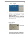
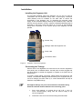
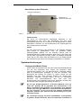
Front Panel LEDs
The green power LED in the upper left part of the Manager front door
indicates the general state of readiness. Two additional LEDs are located
on the front door of the Manager unit to show the system status of the
degasser unit.
POWER (Green)
Indicates when power is applied to the Vacuum Degasser unit (realised
by the Smartline Pump 1000).

Vacuum Degasser Unit 15
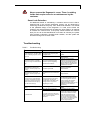
POWER LED INIT / READY LED
Figure 7 Front view of Smartline Manager with Degasser LEDs
INIT (Orange)
Indicates when the vacuum level is outside of the acceptable operating
range. Normally it will come on at initial power-up and remain lit during
pump down. It will go off in a few seconds when the vacuum level
goesbelow 100 mm of Hg (133 mbar) absolute. If an error occurs, this
LED will flash in one of two modes:
Flashing on and off in even 1-second intervals: pump was not able to
reach vacuum set point, indicating a possible leak in the system.
Flashing on for 1 second and off for 2 seconds indicates a vacuum signal
error. Please contact your Service.
READY (Green)
Indicates when vacuum level is within acceptable operating range.
Normally it will come on after the initial pump-down, and remain on as
long as the Vacuum Degasser is powered up and vacuum level is below
100 mm of Hg absolute.
Rear Panel Connections
Connection with
Smartline Pump 1000
Degasser Exhaust
Figure 8 Rear view of Smartline Manager with Vacuum Degasser Unit
Exhaust Port
The gas pumped out of the vacuum chamber leaves the unit through the
exhaust port (see Figure 8). You can connect a gas tubing to the exhaust
port to avoid contaminating the laboratory with solvent gas molecules.

16 Vacuum Degasser Unit
Pump
The degasser unit will be automatically switched on when the Smartline
Pump 1000 is switched on. The Smartline Manager must be connected
with the pump by a special gray control cable (G0649). The cable must
be once connected to the rear panel of the Smartline Pump 1000 in the
“Manager” port and connected to the Smartline Manager 5000 “Pump”
port (see Figure 8). This cable supplies the power for the Smartline
Manager 5000 and must be installed.
System Requirements
Solvents/Mobile Phase
Use only HPLC grade solvents in all analyses. Teflon AF
®
membranes
are low in extractables and are very inert, so the degassing System can
be used with most solvents including THF and Methylene Chloride. After
using saline buffer all lines must be rinsed with water. Do not let the
degasser sit for a long period of time with water or buffered soluble
solutions. It can lead to a microbacterial growth and/or crystallization.
This can result in degasser function defect. Rinse the degasser with
isopropanol (always pay attention to the miscibility of the sequential
solvents used) if it is not going to be operated for a long period of time
(see also page 21 Shut down).
The degassing membrane in the Vacuum Degasser is manufactured
from Teflon AF
®
. As with older membranes manufactured from
PTFE, Teflon AF
®
is inert to all solvents normally used in HPLC.
However, Teflon AF
®
is soluble in perfluorinated solvents such as
Fluorinert
®
FC-75 and FC-40 and Fomblin perfluoro polyether
solvents from Ausimont. In addition, Freon
®
solvents will adversely
affect Teflon AF
®
. Use of such solvents in the Vacuum Degasser will
result in the dissolution and hence destruction of the membrane.
Use proper care when handling flammable solvents. Make sure that
there are no leaks in the solvent lines. Ensure that hazardous
exhaust gases are properly vented.
Chemical compatibility
All parts that contact the mobile phase are made of PEEK, Kel-F
®
,
Tefzel
®
or Teflon AF
®
. PEEK is not recommended for nitric acid, sulfuric
acid and halogenated acid. Organic ethers (THF, MTBE, DMSO) tend to
make it swell.
Space Requirements
The Vacuum Degasser Unit is integrated in the Smartline Manager 5000.
The Smartline Manager 5000 is designed to sit on a bench top, and is
situated in the Smartline LC system between the Smartline eluent tray
and Smartline Pump 1000. The Smartline Manager Unit needs a space of
226 x 135 x 390 mm (W x H x D). No additional space is required in front,
because the tubes are covered by the front door.
Electrical Power Requirements
The AC adapter supplied with the Smartline Pump 1000 incorporates a
universal AC input. This allows the instruments to operate at any AC line
voltage from 90 to 260 V with a line frequency range of 47 to 63 Hz. With
the special gray connection cable (G0649) a regulated voltage of 24V is
supplied to the degasser unit.

Vacuum Degasser Unit 17
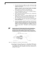
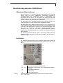
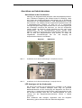
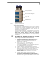
Installation
Installing the Degasser Unit
The Smartline Manager 5000 with degasser unit can only be used in
combination with the Smartline Pump 1000. A special gray connection
cable (G0649) must be installed on the back side to ensure the
functionality of the degasser unit. To guarantee the electrical power
supply of the Smartline Manger 5000 by the Smartline Pump 1000 the
devices must be placed in a tower, where the Smartline Manager 5000 is
arranged on the Pump 1000 (see Figure 9). As soon as the Smartline
Pump 1000 is switched on the vacuum pump of the degasser unit will
operate.
Figure 9 Smartline Tower Arrangement
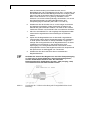
Connecting the Tubings
Solvent lines to be degassed are connected to the Vacuum Degasser’s
front panel ports, as detailed below. Unused ports must be plugged with
the blind fittings to enable the degasser to operate at its peak level of
performance.
To make a proper tubing connection, please follow the instructions and
scheme. The Smartline Manager 5000 accessory kit is equipped with pre-
cut PFTE tubings (see also Table 3). A colour identification will help to
install the compatible tubings.
All supplied tubings are pre-cut and should be installed to bring
about the shortest distance between the connecting ports.
1. Run a blue marked 1 m solvent line of 1/8” O.D. x 1/16” I.D.
PTFE chromatography tubing from the solvent supply to the
Vacuum Degasser.
2. Install at the one end of the solvent tubing the eluent filter.
Solvent Tray
Manager 5000 with Degasser Unit
Pump 1000
UV Detector 2500

18 Vacuum Degasser Unit
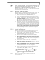
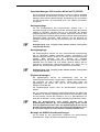
3. Push the tubing through a PEEK 1/8” male ¼-28 fitting and slide
a ferrule over the tubing end (see Figure 10). Cut the Teflon
tubing so the end is flat.
Screw the ¼-28 fitting into one port on the front of the Vacuum
Degasser (channel A with blue marked tubing, for example).
Please follow the flow direction on the Degasser unit.
4. The analytical version is to be connected horizontally →
and the semipreparative version is to be connected vertically ↑
(comparing to Figure 5 and Figure 6).
5. Plastic connectors should be tightened by hand. Overtightening
them will damage the threads.
6. Repeat steps 1 through 3 to connect additional lines to be
degassed (channel B with yellow marked tubing, channel C with
black marked tubing and channel D with red marked tubing.
7. Once all desired solvent lines have been connected to the
Vacuum Degasser, any and all unused ports should be plugged.
Use the plugs supplied.
8. Prime each degassing membrane by pulling the solvent from the
reservoir through the degassing system. This can be done by
connecting a syringe to the tubing or LC pump priming port and
drawing air and/or mobile phase into the syringe until no air
remains in the tubing, approximately 2 milliliters in case of
analytical version and 8 – 10 milliliter in case of semipreparative
version.
DO NOT prime the membranes by pushing solvent through the
degassing systems. This technique can generate several hundred
pounds of pressure which might rupture the membrane, even
though the Teflon AF
®
membrane is quite rugged. The maximum
recommended pressure on the membrane is 1 mPa (100 psig, 7 bar).
Figure 10 Configuration of ¼-28 Nut, Ferrule and Tubing
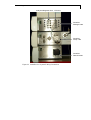
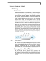
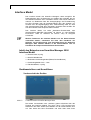
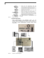
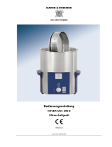
Connecting the Vacuum Degasser in a Smartline LPG System
The following picture shows the tubing connections that are typically
made between the Vacuum Degasser Unit and other instruments in a
Smartline LPG system.

Vacuum Degasser Unit 19
analytical Degasser Unit LPG Unit
Figure 11 Smartline LPG System Tubing Connections
Smartline
Manager 5000
Smartline
Pump 1000
Smartline
Detector 2500
A
B
C
D
A
B
C
D
Seite wird geladen ...
Seite wird geladen ...
Seite wird geladen ...
Seite wird geladen ...
Seite wird geladen ...
Seite wird geladen ...
Seite wird geladen ...
Seite wird geladen ...
Seite wird geladen ...
Seite wird geladen ...
Seite wird geladen ...
Seite wird geladen ...
Seite wird geladen ...
Seite wird geladen ...
Seite wird geladen ...
Seite wird geladen ...
Seite wird geladen ...
Seite wird geladen ...
Seite wird geladen ...
Seite wird geladen ...
Seite wird geladen ...
Seite wird geladen ...
Seite wird geladen ...
Seite wird geladen ...
Seite wird geladen ...
Seite wird geladen ...
Seite wird geladen ...
Seite wird geladen ...
Seite wird geladen ...
Seite wird geladen ...
Seite wird geladen ...
Seite wird geladen ...
Seite wird geladen ...
Seite wird geladen ...
Seite wird geladen ...
Seite wird geladen ...
Seite wird geladen ...
-
 1
1
-
 2
2
-
 3
3
-
 4
4
-
 5
5
-
 6
6
-
 7
7
-
 8
8
-
 9
9
-
 10
10
-
 11
11
-
 12
12
-
 13
13
-
 14
14
-
 15
15
-
 16
16
-
 17
17
-
 18
18
-
 19
19
-
 20
20
-
 21
21
-
 22
22
-
 23
23
-
 24
24
-
 25
25
-
 26
26
-
 27
27
-
 28
28
-
 29
29
-
 30
30
-
 31
31
-
 32
32
-
 33
33
-
 34
34
-
 35
35
-
 36
36
-
 37
37
-
 38
38
-
 39
39
-
 40
40
-
 41
41
-
 42
42
-
 43
43
-
 44
44
-
 45
45
-
 46
46
-
 47
47
-
 48
48
-
 49
49
-
 50
50
-
 51
51
-
 52
52
-
 53
53
-
 54
54
-
 55
55
-
 56
56
-
 57
57


Knauer Smartline Manager 5000 Benutzerhandbuch
- Typ
- Benutzerhandbuch
in anderen Sprachen
Verwandte Artikel


Andere Dokumente
-
Hach TitraLab AT1222 Basic User Manual
-
 Seto RP72 LED ___ Instructions Manual
-
Laserliner SmartLine-Laser 360 Bedienungsanleitung
-
Laserliner SmartLine-Laser 360° Plus Bedienungsanleitung
-
Laserliner SmartLine-Laser G360 Bedienungsanleitung
-
 Ismatec ISM918A Bedienungsanleitung
-
Bachmann 119.272 Datenblatt
-
 Thermo Fisher Scientific UltiMate 3000 Series Installationsanleitung
-
Agilent Technologies InfinityLab Flex Bench Assembly And Use Instructions
-
 HAVER & BOECKER USC 200 S Operating Instructions Manual


